

Page 1
Owner's Manual
Liquid Propane Patio Heater
Model 141.229952
Customer Service Helpline; If you have questions about assembly or operation, or if there are
damaged or missing parts when you unpack this unit from the shipping box, call us Sam - 8pm GST,
Monday through Friday at; 1-888-317-7642
WARNING:
A
Read this Owner's Manual carefully and be sure
your patio heater is properly assembled, installed
and maintained. Failure to follow these instructions
could result in serious bodily injury and/or property
damage. This patio heater is intended for outdoor
use only and is not intended to be installed in or on
recreational vehicles or boats.
Note to Installer: Leave this Owner’s Manual
with the consumer after delivery and/or
installation.
Note to Consumer: Leave this Owner's Manual
in a convenient place for future reference.
Sears, Roebuck and Co.,
Hoffman Estates, IL 60179 U.S.A.
P46B7A- Rev: 10/16/2004
Page 2

Table of Contents
Read These Safety Instructions
Warranty
Safety Instructions
....................................................
.....................................
2
2
Clearance Requirements...........................5
Parts Diagram and Part Lists
..............
6
Assembly Instructions..............................10
Lighting Instructions.................................13
Frequently Asked Questions
...................
14
Full 1-Year Warranty
For one year from the date of purchase Sears will
repair or replace, at our option, any patio heater
part (except for Ignitor battery) that is defective in
material or workmanship.
This warranty does not cover;
• Ignitor battery.
• Reshaping or dents in soft, aluminum Reflector
that may be caused by, but not limited to,
falling debris.
• Patio heater if it is used for commercial or
rental purposes.
This warranty applies only when the patio heater
is used in the United States.
Awarning
Faiiure to comply with these instructions
couid result in a fire or explosion that
could cause serious bodily injury, death,
or property damage.
important Safety Rules:
1. Children and adults should be alert to high
surface temperature of areas above the
post when operating this heater.
2. Children should be carefully supervised
when they are in the area of the heater.
3. NEVER hang anything including clothes or
other flammable items on the heater.
4. DO NOT operate this heater unless it is
fully assembled with Reflector in place.
5. Installation and repair should be done by
a qualified service person. The heater
should be inspected before first use and
at least annually by a qualified service
person. More frequent cleaning may be
required as necessary. It is important that
the patio heater Head be kept clean of
debris to prevent blockage of air flow.
This warranty is void if the patio heater Head
Assembly has been altered or disassembled.
This warranty gives you specific legal rights, and
you may also have other rights which vary from
state to state.
Sears, Roebuck and Co., Dept. 817WA,
Hoffman Estates, IL 60179
A WARNING
Combustion by-products produced when
using this product contain chemicais
known to the State of Caiifornia to cause
cancer, birth defects, or reproductive
harm.
Prior to assembling your patio heater, the
following must be reviewed. Compliance with the
following should result in satisfactory heater
operation. This Owner's Manual should be
retained for future reference. The installation
must conform with local codes of your area.
1. This gas fired infrared patio heater is
intended for heating. The installation must
conform with local codes or, in the absence
of local codes with the National Fuel Gas
code, ANSI Z223.1. In Canada, heater
installation must conform with local building
codes or, in the absence of local codes,
with the current National Standards of
Canada CAN/CGA-B 149.2.
2. The following must be maintained at all times
when the patio heater is in operation:
• Adequate clearance around air openings
into the Combustion Chamber.
• Clearances from combustible materials.
• Provisions for accessibility.
• Combustion and ventilating air supply.
Page 3
3. Proper clearance from combustible materials
must be maintained at all times. Minimum
clearances are as follows;
Sides 24" Top 18"
Below Reflector Head 85"
Combustible materials include wood, compressed
paper, plant fibers, plastic, plexiglás or other
materials capable of being ignited and burned.
Such materials shall be considered combustible
even though flameproof, fire-retardant treated or
plastered. Additional clearance may be required
for glass, painted surfaces and other materials
which may be damaged by radiant or
convection heat.
4. Patio heater must be placed on a level surface.
5. The Gas Manifold supply pressure must be
regulated at 11" water column utilizing a UL
listed regulator. Any replacement regulator must
be UL listed. The minimum inlet pressure to the
regulator from the tank is 10 psi and maximum
pressure is 150 psi.
6. The patio heater must be inspected before each
use, and annually by a qualified service person.
• All gas connections should be checked for leaks
utilizing a soap solution. Never use a flame for
this purpose.
• The heater head and its components must
be kept clear of dirt and cobwebs. Flow
of combustion and ventilation air through
the perforated portions of the heater must
not be obstructed.
• Clean patio heater only with noncombustible,
noncorrosive cleaning agents.
• The stainless steel Emitter Grid should be
kept free of debris. Never spray cleaners
into the Emitter Grid because of potential
harm to internal components. NEVER paint
the Emitter Grid or Reflector.
The Regulator Hose must be protected from
contact with hot or sharp surfaces both
during use and while in storage. Position the
hose so it does not rub against the LP gas
Tank Cover which will be raised and lowered
frequently. The hose assembly must be
visually inspected prior to each use of the
patio heater. If excessive abrasion or wear
is evident, or the hose is cut, it must be
replaced prior to operation. DO NOT use a
Regulator or Hose Assembly other than the
one supplied with the patio heater. The
replacement Hose and Regulator Assembly
may be obtained from your Sears Service
Center or call 1-800-4-IVIY-HOME®
(1-800-469-4663) .
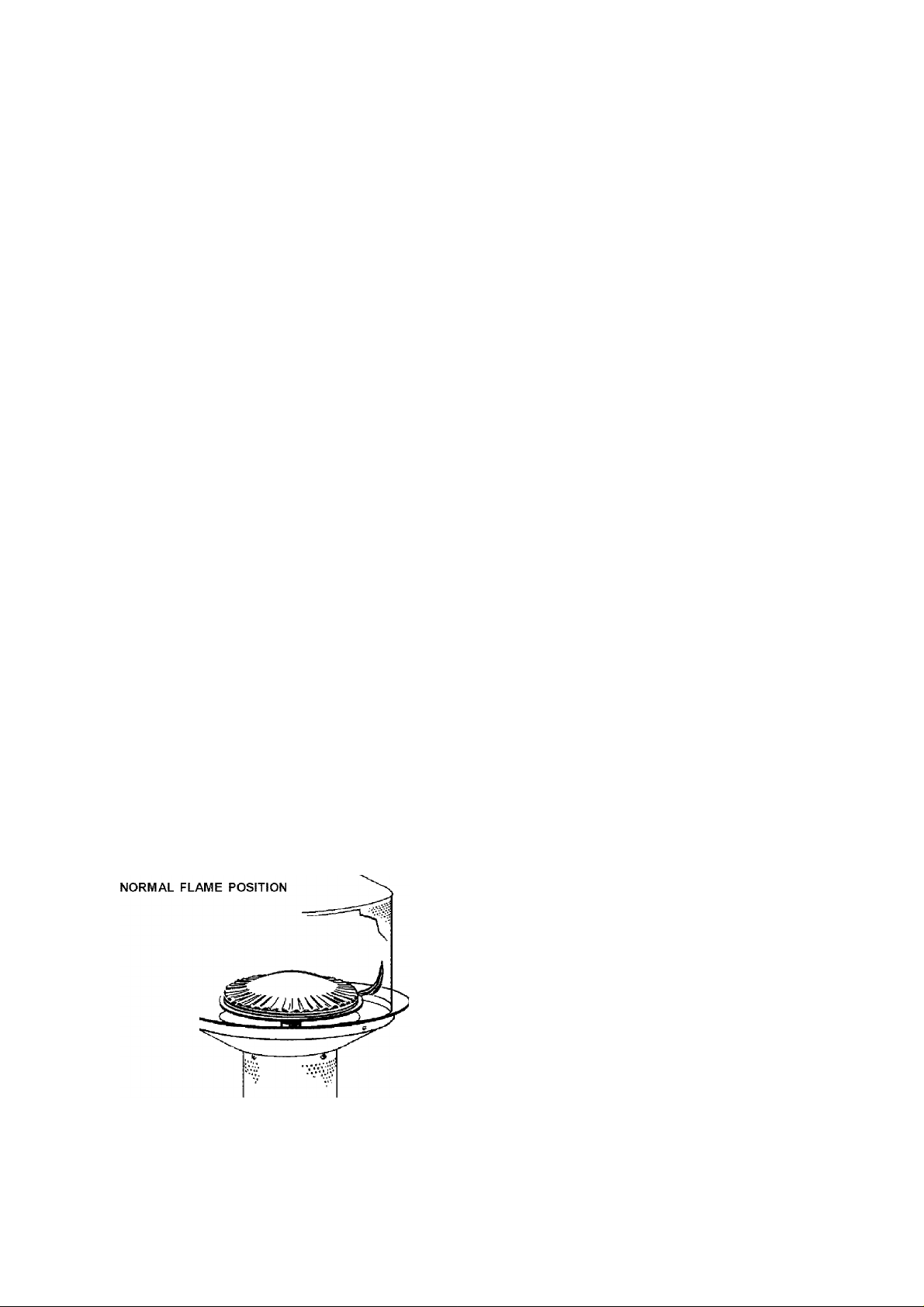
• The flame pattern can be observed through
the perforated emitter grid on the heater
head assembly and should be visually
checked whenever the patio heater is
operated (see Fig. 1). If flames extend
more than 2 inches in height or 1/2 inch
outside the surface of the Emitter Grid or
black soot is accumulating on the Emitter
Grid or Reflector, the heater should be
turned off immediately. The heater should
not be operated again until repairs are
made.
FIGURE 1.
|- 0
2"
- 1"
Awarning
A strong gas smell, or the hissing sound of
gas indicates a serious problem with your
patio heater or the LP gas tank. Failure to
immediately follow the steps listed below
could result in a fire or explosion which
could cause serious bodily injury, death, or
property damage.
• Shut off gas supply to the patio heater.
• Extinguish any open flame.
• Get away from the LP gas tank.
• Do not try to fix the problem yourself.
• If odor continues or you have a fire you
cannot extinguish, call your fire department.
Do not call near the LP gas tank because
your telephone is an electrical device and
could create a spark resulting in fire
and/or explosion.
The patio heater area must be kept clear
and free of combustible materials, gasoline
and other flammable vapors and liquids.
Page 4
8. Installation and use of this patio heater must
conform with local codes or, in the absence of
local codes, with the Standards of Storage and
Handling of Liquefied Petroleum Gases, ANSI/
NFPA 58.
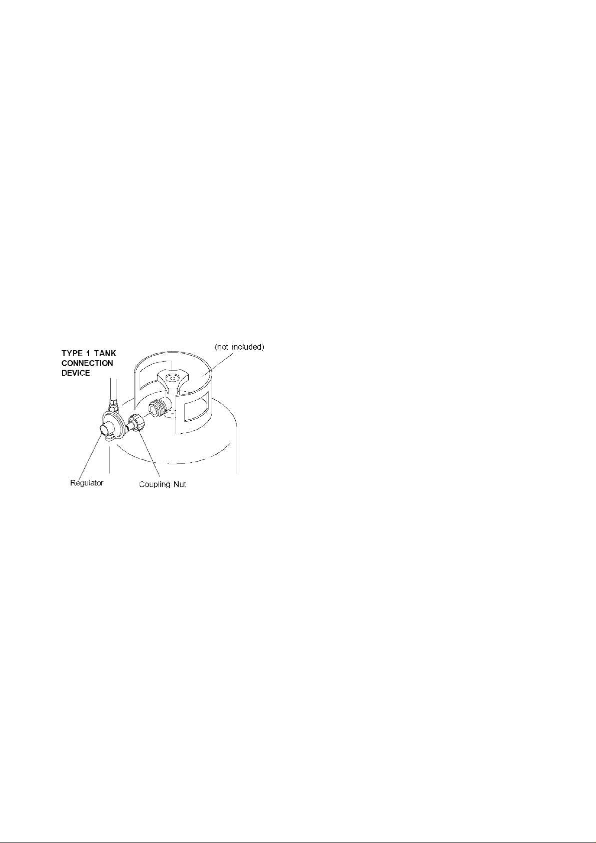
9. This patio heater is designed to operate with a
standard 20 lb. Liquid Propane Gas (LP gas)
tank with Type 1 Tank Connection Device as
shown in Fig. 2. (A.G.A. Requirements 10-94).
The propane tank must (1) be provided with a
shutoff valve. The outlet of the tank valve must
be 1-5/16 ACME male thread specified in Type
1 Tank Connection Device per A.G.A.
requirement 10-94. Per standard, the tank valve
is designed to provide a positive sealing device
for safety; (2) the tank supply system must be
arranged for vapor withdrawal; and (3) the tank
used must include a collar to protect the tank
valve. The LP gas supply tank must be
constructed and marked in accordance with the
specifications for LP gas tanks of the U.S.
Department of Transportation.
Figure 2
Propane Tank
12. Clothing or other flammable materials should
not be hung from the heater, or placed on or
near the heater. The area above the post may
be extremely hot. Direct contact with these
metal surfaces should be avoided in order to
prevent burns or clothing ignition.
13. The patio heater has been designed with several
safety features. These include a 100% safety
shutoff control, elevated heating element, weighted
base, and Type 1 Tank Connection Device.
The Electronic Ignition System is an
advanced feature which makes lighting the
patio heater a very easy and matchless
process. Any modification to the patio heater
not described in the Owner's Manual may
compromise the safety of this appliance and
will void your warranty. Special concern
should be given to the following warnings:
Awarning
• DO NOT shorten the post length
• DO NOT bypass the thermocouple
• DO NOT operate heater without a reflector
• DO NOT operate without the weighted base
• DO NOT attempt to convert the patio heater
for natural gas use.
Failure to comply with these instructions
could result in a fire or explosion which
could cause serious bodily injury, death,
or property damage.
Screw the coupling nut of regulator onto the outlet
tank valve.
10, The tank valve outlet must be maintained in
good condition. When the tank is not
connected to the patio heater, cover the valve
with the tank supplied, dust cap. A leak test
should be performed with soapy water
whenever connecting a new tank. Never use a
match to test for leaks.
11. The propane tank must be turned off whenever
the patio heater is not in use. When the patio
heater is stored indoors, the connection
between the propane tank and the heater must
be disconnected and stored in accordance with
Chapter 5 of the Standard for Storage and
Handling of Liquefied Gases, ANSI/NFPA 58.
14. For outdoor use only. If stored indoors,
detach and leave LP gas tank outdoors. The
LP gas supply tank must be disconnected
when patio heater is not in use,
15. CAUTION: You must use only the gas
regulator provided with this patio heater. This
regulator is set for an outlet pressure of 11
inches water column.
Page 5
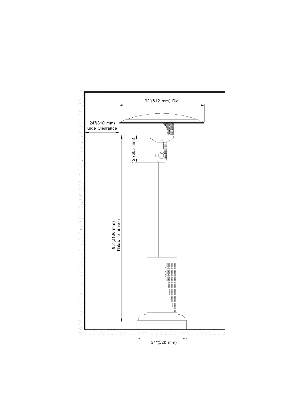
Kenmore LPG Patio Heater
For Outdoor Use Only
^ o
Minimum Ciearance from Combustibies
o
CN
oo
CN
CM
CO
CO
Ci
CO
CO
Page 6

{
----y----
Quantity and Actual Size of Each Hardware Piece:
^
3/8"x1-1/4" Hex Head Screw 3/8" Spring Washer
Qty. 3 Qty. 15
Part # PH001 Part # PH002
(attached to the Weighted Base)
3/16"x1/2" Phillips Head Screw
Qty. 1
Part # PH005
1/4" Spring Washer
Qty. 4
Part # PH009
3/16" Spring Washer
Qty. 1
Part # PH006
1/4" Wing Nut
Qty. 4
Part # PH010
3/8”x3/4" Hex Head Screw
Qty. 6
Part # PH003
3/16" Nut
Qty. 1
Part # PH007
T4x15 Self-Tapping Screw
Qty. 5
Part # PH016
3/8" Cap Nut
Qty, 6
Part # PH004
Safety Chain
Qty. 1
Part # P7083A
Qty. 1
Part # P7079A
One Battery/AA included in Hardware Pack
Hose Holder B
Qty. 1
Part # P7080A
Page 7

Contents for Hardware Pack (Part # P55C9B)
The following table illustrates a breakdown of the hardware pack. It highlights what components are used
in the various stages of assembly.
Ref. Component Qty. to Use
PH002
PH003
PH002
PH004
P7079A
PH003
PH002
PH004
PH016
PH016
PH009
PH010
P7083A
P7080A
PH005
PH006 3/16" Spring Washer 1
PH007
3/8" Spring Washer 3 Install Legs to Weighted Base
3/8"x3/4" Hex Head Screw 5 Install Lower Post to Legs
3/8" Spring Washer 10
3/8" Cap Nut 5
Hose Holder A 1 Install Hose Holder A to Leg
3/8"x3/4" Hex Head Screw 1
3/8" Spring Washer 2
3/8" Cap Nut 1
T4x15 Self-Tapping Screw 4 Install Heater Head Assembly to Upper Post
T4x15 Self-Tapping Screw 1 Install Upper Post to Lower Post
1/4" Spring Washer 4 Install Reflector to Emitter Grid
1/4" Wing Nut 4
Safety Chain 1 Install Safety Chain to Legs
Hose Holder B 1 Install Hose Holder B to Hose Holder A
3/16"x1/2" Phillips Head Screw 1
3/16" Nut 1
Purpose of Components
One Battery/AA included in Hardware Pack
Page 8

Parts Diagram
Remove all components from the packing carton and place within easy reach. Inspect patio heater parts for
damage as you proceed. Do not assemble or operate your patio heater if parts appear damaged.
Assembly is
pre-assembled
for your
convenience.
Page 9

Parts List
REF# DESCRIPTION PART# QTY
1. Aluminum Reflector
2. Heater Head Assembly
3. Rubber Rim P7073A 1
4. LP Gas Tank Cover
5. Upper Post
6. Stainless Steel Fuel Hose
7. Lower Post P7077A 1
8. Leg
9. Hose Holder A
10. Hose Holder B
11. Gas Regulator Assembly P7081A 1
12. Chain Hook with Nut (Left)
13. Chain Hook with Nut (Right)
14. Safety Chain
15. Cast Iron Base P7085A 1
...
Owner's Manual
...
Hardware Pack (contents pg.6/7)
P7055A
P7086A
P7074A
P7075A
P7076A
P7078A
P7079A
P7080A
P7082A
P05514045A 1
P7083A
P46B7A
P55C9B
1
1
1
1
1
3
1
1
1
1
1
1
If there are damaged or missing parts when you
unpack this unit from the shipping box, or you have
questions about assembly, call the Customer Ser
vice Helpline 8 am - 8 pm CST, Monday through
Friday at 1-888-317-7642.
For the repair or replacement parts you need:
Call anytime, day or night
1-800-4-MY-HOME ®(1-800-469-4663)
To make sure you obtain the correct replacement
parts for your Kenmore patio heater, please refer
to the part numbers on this page. The following
information is required to assure you receive the
correct parts:
1. Model Number (found on the CSA label
located on the back of patio heater head.
See Fig. 1 below.)
2. Part Number
3. Part Description
4. Quantity of parts needed
Important; Keep this Owner’s Manual for conve
nient referral and for part replacement.
Important: Use only Sears authorized parts. The
use of any part that is not Sears authorized can
be dangerous and will also void your product
warranty.
CSA label
located here
Page 10

Assembly Instructions
Tools Required for Assembly
Before assembling the patio heater, use the parts
list to check that all necessary parts have been
included. Inspect patio heater for damage as you
proceed. Do not assemble or operate the patio
heater if it appears damaged. If you have ques
tions during the assembly process, call 1-888-317
7642, 8am - 8pm CST, Monday through Friday.
CAUTION;
While it is possible for one person to assemble
this patio heater, we recommend you have assis
tance when attaching the Reflector, heater Head
Assembly and threading the stainless Fuel Hose.
Remove all parts and hardware from carton. Refer
to the parts list and hardware pack illustrations
and assemble the patio heater on a protective
work surface to avoid scratching heater surfaces.
1. Unscrew the three 3/8"x1-1/4" Hex Head
Screws from the Weighted Base.
Loosely install the two Legs with Hooks onto
Weighted Base by using 2 of the 3/8" Spring
Washers and the detached 3/8''x1-1/4" Hex
Head Screws. Make sure the Hooks are in
the front for the Safety Chain. See Fig. 1.
• Protective gloves
• Eye protection
• One #2 Phillips Head Screwdriver
• Two Adjustable Wrenches
Figure 1
3/8"x1-1/4" HEX HEAD SCREW DETACHED
FOR LEG INSTALLATION
Loosely install the third Leg using a 3/8"
Spring Washer and the detached 3/8"x1-1/4"
Hex Head Screw.
2. Hang the Safety Chain on the Hooks of both
Legs.
3. Attach the Lower Post (with bracket) onto the
top of Legs by using 5 of the 3/8"x3/4" Hex
Head Screws, 10 of the 3/8" Spring Washers
and 5 of the 3/8" Cap Nuts in sequence as
shown in Fig. 2. Use adjustable wrench to
tighten the Nuts.
4. Secure Hose Holder A to the right Leg using
1 of the 3/8"x3/4" Hex Head Screw, 2 of the
3/8" Spring Washers and 1 of the 3/8" Cap
Nut. See Fig. 2. Use adjustable wrench to
tighten the Nut.
5. Tighten the loosely attached screws from
Steps 1, 3 and 4.
6. Straighten the Corrugated Stainless Steel Fuel
Hose and insert it through the Upper Post as
shown in Fig. 3.
Figure 3
HEATER HEAD
With another person holding the Upper Post
upright, attach the Heater Head Assembly to
the top of Upper Post using 4 of the T4x15
Self-Tapping Screws provided.
INSIDE
10
Page 11

/.Attach the Reflector onto Emitter Grid by
using 4 of the 1/4" Spring Washers and 1/4"
Wing Nuts provided. See Fig. 4.
8. Slide the Tank Cover through the Lower Post
and onto the Weighted Base. See Fig. 5.
9. Lift the assembled Upper Post and insert the
balance of the Fuel Hose through Lower Post.
10, Keep the Upper Post slightly lifted and turn it
until its screw hole faces the same direction
as the sliding channel of the Lower Post.
Slide Upper Post into Lower Post, until the
holes on both posts align. Tighten securely
using 1 of the T4x15 Self-Tapping Screws
provided.
11, Raise the Tank Cover and tilt it sideways until
it rests onto the bracket of the Lower Post.
Connect the hose end fitting of the Regulator
Assembly to the stainless steel Fuel Hose.
Tighten securely with two adjustable wrenches,
12, Carefully bend the stainless steel Fuel Hose
at a 90 degree angle. Hold the connected
hose fittings against the installed Hose Holder
A, and secure Hose Holder B to Hose Holder
A by inserting the Fastening Strip into the
slot of Hose Holder A. Tighten firmly using
the 3/16"x1/2" Phillips Head Screw, and the
3/16" Spring Washer and 3/16" Nut provided.
Use adjustable wrench to tighten the Nut,
Figure 4
<á
Figure 5
11
Page 12

Ignitor Battery Installation - See Fig. 6
1. Unscrew the Ignitor Cap located on the
Heater Head Assembly and remove the Con
tact and Spring from the Ignitor Slot.
2. Place the supplied AA battery into the Ignitor
Slot with the positive pole facing outward.
See Fig. 6.
Figure 6
1.5 V, BATTERY (AA size)
IGNITOR
CAP
CONTACT SPRING IGNITOR SLOT
HEATER HEAD
ASSEMBLY
2. Check the tank valve feature to ensure it has
proper external mating threads to fit the Hose
and Regulator Assembly provided. (Type 1
connection per ANSI Z21.58a-1998)
3. Make sure the Burner Valve is in the OFF
position.
4. Inspect the valve connection port and Regula
tor Assembly. Remove any debris and inspect
hose for damage. Never attempt to use
damaged or plugged equipment.
5. When connecting the Hose and Regulator
Assembly to the tank valve, hand tighten nut
clockwise to a full stop. Do Not use a
wrench to tighten because it could damage
the Quick Coupling Nut and result in a
hazardous condition.
3. Place the Spring over the AA battery, then
place the Contact on top of the Spring.
Screw the Ignitor Cap back onto the Heater
Head Assembly. See Fig. 6.
Connecting A Liquid Propane Gas (LP gas)
Tank To Your Patio Heater
1. Raise LP Tank Cover and unhook the safety
chain. Place your filled gas tank on the
Weighted Base. Hang the Safety Chain on
the Hooks of both Legs using the chain links
which hold your tank most securely. See Fig.
7. Make sure the LP gas tank valve is in the
full OFF position. (Turn clockwise to close.)
NOTE: When connecting the LP gas tank,
position the tank so its Hose and Regulator does
not interfere or rub against the Tank Cover which
will be raised and lowered often, possibly causing
damage to the hose.
Figure 7
TYPE 1 TANK
CONNECTION DEVICE
6. Open the tank valve fully (counterclockwise).
Use a soapy water solution to check all
connections for leaks before attempting to
use your patio heater. If bubbles appear in the
soap solution the connections are not properly
sealed. Check each fitting and tighten or repair
as necessary.
If you have a gas leak that cannot be repaired
by tightening, turn off the gas at the source,
disconnect fuel line from your patio heater and
call 1-800-4-MY-HOME® or your gas supplier for
repair assistance.
Disconnecting A Liquid Propane Gas (LP gas)
Tank From Your Patio Heater
1. Turn the Burner Valve and LP gas tank valve
to the full OFF position. (Turn clockwise to
close.)
2. Detach the Hose and Regulator Assembly
from the LP gas tank valve by turning the
Quick Coupling Nut counterclockwise.
CAUTION: When the patio heater is not in use,
the gas must be turned off at the supply tank.
Congratulations
Your Kenmore Patio Heater is now ready for
use. Before the first use and at the begin
ning of each season (and whenever the LP
gas tank has been changed):
1. Read all safety, lighting and operating
instructions.
2. Check Gas Valve Orifices, Burner Tubes
and Burner Ports for any obstructions.
3. Perform Gas Leak Check according to
instructions found on page 13 of this
manual.
12
Page 13

Checking For LP Gas Leaks
Never test for leaks with a flame. Prior to first
use, at the beginning of each season, or every
time your LP gas tank is changed, you must
check for gas leaks. Follow these four steps;
1. Make a soap solution by mixing one part
liquid detergent and one part water.
2. Turn the Control Knob to the full OFF
position, then turn the gas ON at source.
3. Apply the soap solution to all gas
connections. If bubbles appear in the soap
solution the connections are not properly sealed.
Check each fitting and tighten or repair as
necessary.
4. If you have a gas leak that cannot be repaired
by tightening, turn off the gas at the source,
disconnect fuel line from your patio heater and
call 1-800-4-MY-HOIVIE® or your gas supplier for
repair assistance.
Warning: Improper installation, adjustment, alteration,
service or maintenance can cause injury, death or
property damage and will void your product warranty.
Lighting Instructions
Note; At first use, the Patio Heater Reflector
may emit a slight odor and smoke due to the
burn-off of oils used in the manufacturing
process of this aluminum part. This is to be
expected.
1. Familiarize yourself with the safety instructions
and warnings at the front of this Owner’s Manual.
Do not smoke while lighting patio heater or check
ing gas supply connections. Be sure your patio
heater is placed in accordance wth the minimum
clearance from combustibles as shown on page 5
of this Owner's Manual.
2. Be sure the LP gas tank is filled.
7. Release the Control Knob and turn to "ON".
8. If the patio heater does not light you may
need to purge air from the gas line or reset
the regulator excess gas flow device. Note;
this procedure should be done every time a
new LP gas tank is connected to your patio
heater.
To purge air from your gas line and/or
reset the Regulator excess gas flow
device:
• Turn the Control Knob to the off position.
• Turn off the gas at the tank valve.
• Disconnect Regulator from the LP gas
tank.
• Let unit stand for 5 minutes.
• Reconnect the Regulator to LP gas tank.
• Turn the tank valve on slowly until 1/4 to
1/2 open.
• Follow lighting steps 5 through 7 listed on
this page.
Awarning
A strong gas smell, or the hissing sound of
gas indicates a serious problem with your
patio heater or the LP gas tank. Failure to
immediately follow the steps listed below
could result in a fire or explosion which
could cause serious bodily injury, death, or
property damage.
• Shut off gas supply to the patio heater.
• Extinguish any open flame.
• Get away from the LP gas tank.
• Do not try to fix the problem yourself.
• If odor continues or you have a fire you
cannot extinguish, call your fire department.
Do not call near the LP gas tank because
your telephone is an electrical device and
could create a spark resulting in fire
and/or explosion.
3. Make sure all gas connections are securely
tightened.
4. Set Control Knob to "OFF" and open the LP gas
tankvalve.
5. Push and hold the Control Knob, then slowly turn it
to "PILOT". The Ignitor will continuously spark at
the same time.
6. Look through the 1/2" Manual Lighting Hole to
see if the Pilot Flame is lit. If lit, continue
pressing the Control Knob for 15 seconds to
ensure the Pilot Flame remains on. If the
pilot is not lit, turn the Control Knob to
"OFF", and wait 5 minutes for gas to clear
before attempting to light again.
13
Page 14

Frequently Asked Questions
Question: Why won’t the pilot stay lit?
Answer:
Question; Who do I call with questions about my
Kenmore Patio Heater assembly or if parts are
damaged or missing from my shipping box?
Answer: Call the Customer Service Helpline
Sam - 8pm CST, Monday through Friday, at
1-888-317-7642.
Question: Can I convert my Kenmore Patio Heater
from LP gas to natural gas?
Answer: No, this patio heater is manufactured to exact
specifications and is CSA Design Certified for LP gas
use only. For your own safety, conversion kits are not
available and any attempt to convert your patio heater to
natural gasvwll void your product warranty.
Question: Why doesn't the Hose and Regulator Assem
bly supplied with my new patio heater fit the older LP
gas tank I’ve used for years?
Answer: The U.S. Government regulates gas appliances
and LP gas tanks. Whenever new regulations are
passed the LP gas tank fittings are altered. If your
current tank does not fit the hose and regulator supplied
with your new patio heater, the tank is outdated and
must be replaced.
Question: When I originally started my patio heater
there was some smoke and an odor coming from the
Reflector. Is this normal?
Answer: Yes, at first use, the Patio Heater Reflector
may emit a slight odor and smoke due to the burn-off
of oils used in the manufacturing process of this
aluminum part. This is to be expected.
• May be excessive winds. Position your patio
heater in a more protected area away from winds
of 10 mph or more, with proper clearances.
• Remove the Emitter Grid to clean the Pilot head
or you need a service call the Customer Service
Helpline 8am - 8pm CST, Monday throught Friday
at 1-888-317-7642.
• The Pilot Light Assembly or GM20 Gas Valve
may be broken in which case you need to order
the Heater Head Assembly. See the Parts List
on page 9.
Question: The patio heater burner won’t light. Why?
Answer:
• The Pilot Burner is not lit.
• Low gas pressure. Be sure LP gas tank is filled.
• Manual valve not in "ON" position.
• The gas line may need to be purged. Follow
the Purging Instructions found under Lighting
Instructions on page 13, step 8.
Question: How should I clean my patio heater?
Answer; Keep the heater head and its components
clear of dirt cobwebs by brushing or wiping the areas
clean. Do not spray cleaners into the emitter grid
because of potential harm to internal components.
The stainless steel Post, Tank Cover, Base and Alumi
num Reflector can be cleaned with a stainless steel
spray cleaner and a soft cloth. Do not use gasoline,
paint thinner or any other cleaning agent that can be
combustible or corrosive.
Question; I expected an 8 to 12 foot radius of warmth
from my patio heater but that seems to vary, sometimes
greater and sometimes vwth less coverage area. What
affects this radius?
Answer; Various weather conditions as well as the
placement of your patio heater can affect the radius.
Without winds and with temperatures above 40
degrees Fahrenheit you can warm a radius up to 12
feet. Higher winds and colder air will reduce the
warming radius.
Question: Sometimes the pilot will not light. What are
some possible causes of this?
Answer:
• May be air in the gas line or the Regulator
excess flow device may need to be reset.
Both are accomplished with one process.
See instructions found under Lighting
Instructions on page 13, step 8.
• Low gas pressure. Be sure LP gas tank is filled.
• Be sure the LP gas tank valve is open.
• Ignitor battery may need replacing.
Question: Where can I buy replacement parts?
Answer: For the repair or replacement parts you need
call anytime, day or night 1-800-4-MY-HOME ®
(1-800-469-4663). Use only Sears authorized parts.
The use of any part that is not Sears authorized can be
dangerous and will also void your product warranty.
Question; Sometimes I hear a humming sound
coming from my regulator. What causes this?
Answer: This is not to be confused with the "hissing"
sound associated with leaking gas. The humming noise
you may hear is the sound of gas flowing through the
Regulator. You may have heard a similar sound at the
gas meter at your home. Reasonable humming should
be expected and will not affect the performance of
your patio heater.
14
Page 15

Get it fixed, at your home or ours!
For repatr-ln f©yf tiome-of all ma|or brand appfianoes,
lawfi and garden igyipmeri!, or lieaing and cooliif spteim,
nO' inalter wtio made It, no matter who sold Iti
For lie replacement parts, accessories and
owner's nranyals that you need to do-it-yourself.
Fnr Fe3'i onal iristiliaion of horn# appliances
and items life garage door ^openers and water heatef^.
1-8ii-4-IIY-HOiiE® |i-S0i-4SS-4«f3|
Call anytime, day or night (U.S.A. and Canacfal
'шщм-'Лшшш.тт
Out Heine
For repair -of carry-in ilems like vacyijms, lawn equipment,
3rd elecimmcs calí or go on-line for tie location of your ilea/nest
№W.searï.ca
Sears Parts & Repair Center.
1^800-488^1222
Cal anytime,, day or night ÍÜ.S..A. only)
^wr,sei;fs.cenrt
To purchase a protectton адгеетеш. (U..S.-A.)
or Ilia in tena nee agreern---it tCd-ieda i on н рк ouc^ ь-' by Sears:
MW-827-ÍSSi tu,SA.) 1-8W-3Í1-8SSÍ íCtradaí
Pars ps'dr serveo cte герагаабл
a domiciio, у para oirdenar piezas:
1-iSi-Sy-HOGAR*
n Ito T4 -Ato:
...
.
Bioistered Tradenieifc i ’• líaosintrare:. :á#i¥Íw '118*'о1 ■бшя, R^itoudt end Oe,
» i '** Metei -eli t “ Marw de Sewrie di' Si«m, RsetaLci*. and Cs
|П'*'Мвш§ tMomim ite ief*. Reetaj* шй Co.
Áu Canada роуг sewice en français:
1-800-LE-FOYER’-’-
•'•bj.i: ,vo.;
w¥#w.8€ars.ca
 Loading...