

Kenmore 141.17682, 141.16684, 141.17684, 141.16682 Owner's Manual
L I
OPERATOR'S MANUAL
®
Liquid Propane Gas (LPG)
Grill
Natural Gas (NG) Grill
• Safety
• Assembly Model 141.16682 and141.17682
• Use and Care
• Cooking Guide
• Frequently Asked Questions
Model 141.16684and 141.17684
Call us first if you have any problem with this
product. We can help you with questions about
assembly and grill operation or if there are
damaged or missing parts when you unpack
this unit from the shipping box. Please call
before returning to the store.
1-888-317-7642
8am-8pm CST, Monday throuqh Friday
• NOTE TO ASSEMBLER / INSTALLER:
Leave this manual with the consumer.
• NOTETO CONSUMER:
Keep this manual for future reference.
• RECORD YOURSERIAL #
(see silver CSA label on main body of grill)
Failure to comply with these instructions could
result in a fire or explosion that could cause
serious bodily injury, death or propertydamage.
Whether this grill was assembled by you or
someone else, you must read this entire manual
before using your grill to ensure the grill is
properly assembled, installed and maintained.
Use your grill at least 3 feet away from any
wall or surface. Use your grill at least 3 feet
away from combustible objects that can melt or
catch fire (such as vinyl or wood siding, fences
and overhangs) or sources of ignition including
pilot lights on water heaters and live electrical
appliances.
THIS GAS APPLIANCE IS DESIGNED FOR
OUTDOOR USE ONLY.
Combustion byproducts produced when using
this product contain chemicals known to the
State of California to cause cancer, birth defects,
or other reproductive harm.
Manual # P80103004A - Date:2005/01/14
Primary Safety Warnings ........................... 1-3
Warranty Terms and Conditions .................. 2
Pre-Assembly Instructions .............................. 3
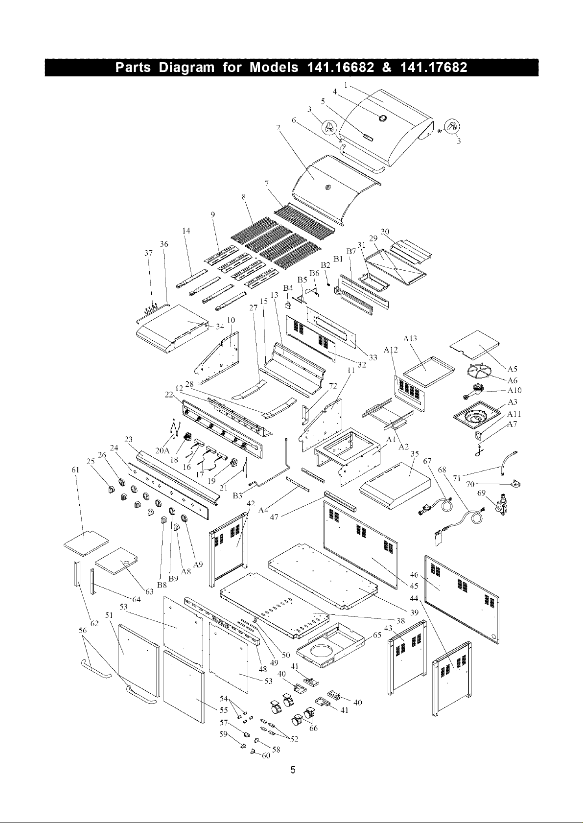
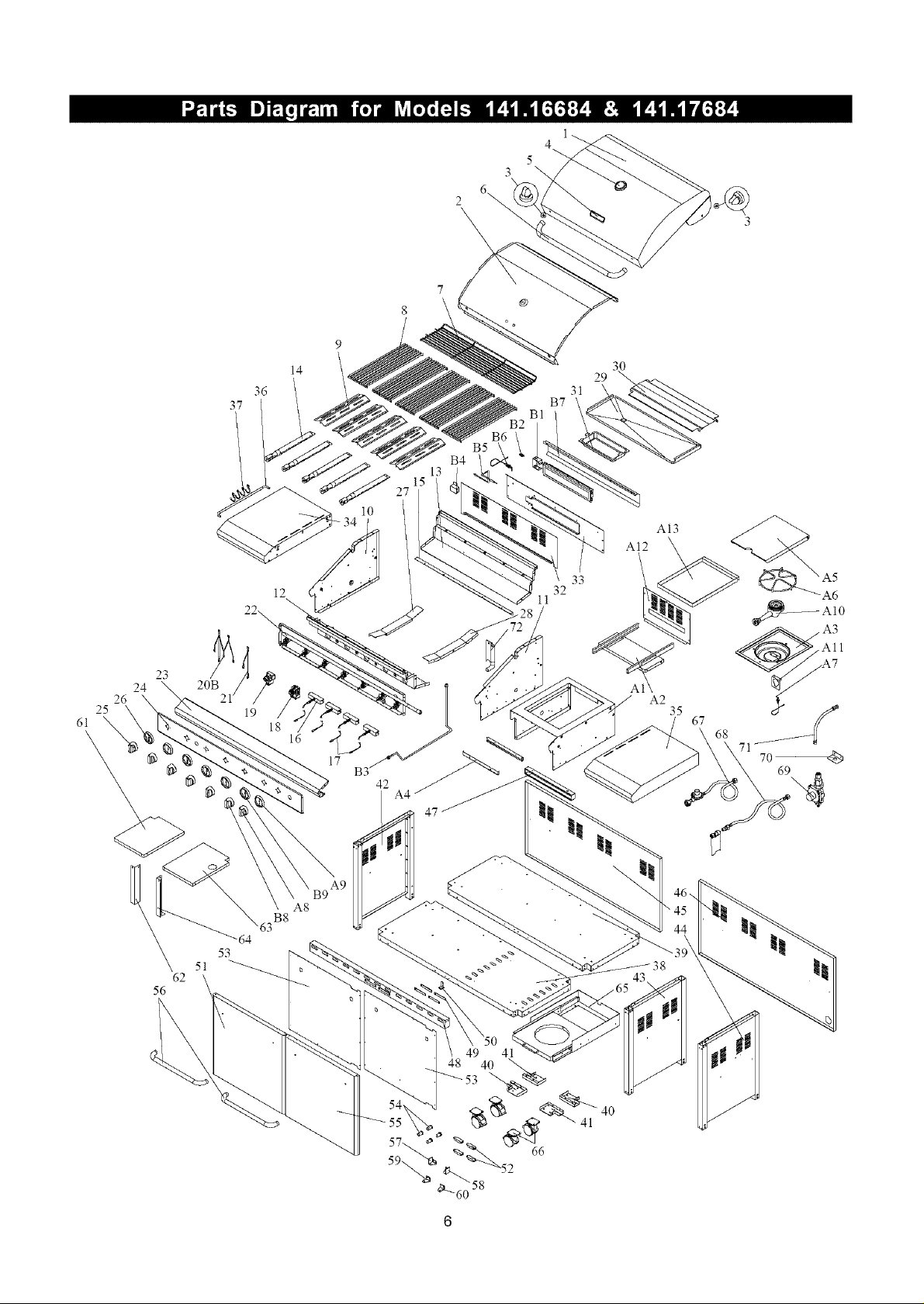
Part Diagrams and Lists .......................... 4-8
Assembly Instructions ............................... 9-10
LP Gas Tank Installation ...................... 11-13
Natural Gas Connection .............................. 14
Use & Care Instructions:
• Lighting Instructions ................................. 15
• Troubleshooting .......................................... 16
Cleaning and Maintenance ..................... 17-18
Cooking Guide ........................................ A1-A6
Frequently Asked Questions ................ A7-A8
Lifetime Limited Warranty on Kenmore Elite
Grill Stainless Steel Parts
For the lifetime of this grill, if any of its stainless
steel parts, except for cooking grids and Savor
Plates TM, is defective in material or workmanship,
Sears will repair or replace the part, at our option,
free of charge.
This warranty does not include discoloration of
stainless steel parts due to normal use or
excessive heat, nor does it include scratches or
dents caused by normal use, accident, or improper
maintenance.
Two-Year Full Warranty on Kenmore Elite Grill
For two years from the date of purchase, if this grill
is defective in material or workmanship, Sears will
repair it free of charge.
If repair proves impossible, Sears will, atyour option,
either replace this grill with a newone, or refund the
full purchase price.
This warranty excludes ignitor batteries and grill paint
loss or rusting, which are either expendable parts
that can wear out from normal use in less than a
year, or are conditions that can be the result of
normal use, accident or improper maintenance.
Limited 3 Year Warranty on Selected Grill Parts
From 2 years after the date of purchase for a
3-year period, Sears will replace Cooking Grids,
Savor Plates TM and All Other Parts (except for
Ignitor battery) if they are defective in material and
workmanship. You will be charged for labor.
Warranty Service
Warranty service is available by contacting
Sears at 1-800-4-MY-HOME ®
Warranty Restrictions
• This warranty is void if grill is used for
commercial or rental purposes.
• This grill is safety certified for use only in
the country where purchased. Modification for
use in any other location is a safety hazard
and will void the warranty.
• This warranty gives you specific legal rights,
and you may also have other rights which
vary from state to state.
Sears, Roebuck and Co., Dept. 817WA,
Hoffman Estates, IL 60179 U.S.A.
© Sears, Roebuck and Co.
IF YOU SMELL GAS:
1. Shut off gas to the appliance.
2 Extinguish any open flame.
3. Open lid.
4. If odor continues, keep away from
the appliance and immediately call
your gas supplier or your fire
department.
1. Do not store spare LP cylinder
within 10 feet (3m) of this appliance.
2. Do not store or use gasoline or
other flammable liquids and
vapors within 25 feet (8m) of this
appliance.
3.When cooking with oil/grease, do
not allow the oil/grease to get
hotter than 350°F (117°C).
4. Do not leave oil/grease unattended.
LPG grill models must be used with Liquid
Propane Gas and the regulator assembly
supplied. Natural Gas models must be used
with Natural Gas only. Any attempt to convert
the grill from one fuel type to another is
extremely hazardous and will void the
warranty.
Never use your gas grill in a garage, porch, shed,
breezeway or any other enclosed area.
Never obstruct the flow of ventilation air around
your gas grill housing.
Keep gas regulator hose away from hot grill
surfaces and dripping grease. Avoid unneces-
sary twisting of hose. Visually inspect hose
prior to each use for cuts, cracks, excessive
wear or other damage. If the hose appears
damaged do not use the gas grill. Call Sears
at 1-800-4-MY-HOME ® (1-800-469-4663) for a
Kenmore replacement hose.
Grill Installation Codes
The installation must conform with local codes or, in the
absence of local codes, with either the National Fuel Gas
Code, ANSI Z223.1/NFPA 54, or CAN/CGA-B149.1, Natural
Gas and Propane installation Code.
Failure to comply with these instructions may
result in a hazardous situation which, if not
avoided, may result in injury,
Spiders and small insects can spin webs and
nest in the grill ing transit and
warehousing flow
obstruction round the
Burner T_ FIRE"
can cau_ ate an
unsafe (
To .'K
FIRE bes
as follc grill.
Also do _ummer
and fall or in your
area, and if used for an
extended perioc
1. Remove the screw from the rear of each Burner
using a Phillips Head Screwdriver.
2. Carefully lift each Burner up and away from the
Gas Valve Orifice.
3. Check and clean Burner/Venturi Tubes for insects
and insect nests. A clogged tube can lead to a fire
beneath the grill.
4. Refer to the figure below and perform one of
these 3 cleaning methods:
[] METHOD 1: Bend a stiff wire or wire coat
hanger into a small hook as shown and run
the hook through the Burner Tube and inside
the Burner several times to remove debris.
TO CLEAN BURNER TUBE, INSERT HOOK
HERE
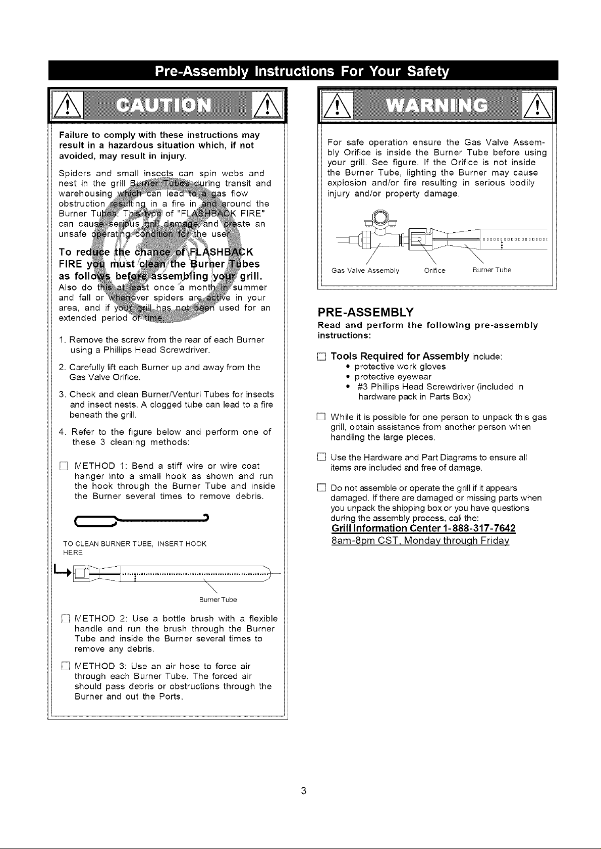
For safe operation ensure the Gas Valve Assem-
bly Orifice is inside the Burner Tube before using
your grill. See figure. If the Orifice is not inside
the Burner Tube, lighting the Burner may cause
explosion and/or fire resulting in serious bodily
injury and/or property damage.
Gas Valve Assembly Orifice Burner Tube
PRE-ASSEMBLY
Read and perform the following pre-assembly
instructions:
[] Tools Required for Assembly include:
• protective work gloves
• protective eyewear
• #3 Phillips Head Screwdriver (included in
hardware pack in Parts Box)
[]
While it is possible for one person to unpack this gas
grill, obtain assistance from another person when
handling the large pieces.
[]
Use the Hardware and Part Diagrams to ensure all
items are included and free of damage.
[]
Do not assemble or operate the grill if it appears
damaged. Ifthere are damaged or missing parts when
you unpack the shipping box or you have questions
during the assembly process, call the:
Grill Information Center 1-888-317-7642
8am-8pm CST, Monday throu.qh Friday
\
BurnerTube
[] METHOD 2: Use a bottle brush with a flexible
handle and run the brush through the Burner
Tube and inside the Burner several times to
remove any debris.
[] METHOD 3: Use an air hose to force air
through each Burner Tube. The forced air
should pass debris or obstructions through the
Burner and out the Ports.
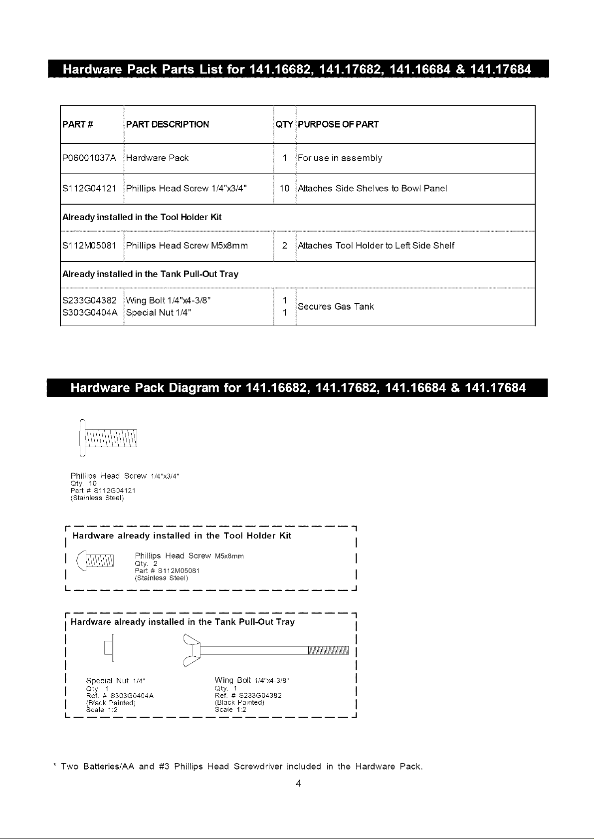
PART # zzPART DESCRIPTION
P06001037A Hardware Pack
Sl12G04121 Phillips Head Screw 1/4"x3/4"
i
1 For use in assembly
10 Attaches Side Shelves to Bowl Panel
Already installed in the Tool Holder Kit
Sl12M05081 Phillips Head Screw M5x8mm 2 Attaches TooI Holder to Left Side Shelf
Already installed in the Tank Pull-Out Tray
Phillips Head Screw 1/4"x3/4"
Qty 10
Part # $112G04121
(Stainless Steel)
I-
Hardware already installed in the Tool Holder Kit
I
I Phillips Head Screw M5xamm
i Part # $112M05081
Qty 2
(Stainless Steel)
I_
Hardware already installed in the Tank Pull-Out Tray
Special Nut 1/4" Wing Bolt 1/4"x4-3/8"
Qty 1 Qty. 1
Ref. # S303G0404A Ref # $233G04382
(BIack Painted) (Black Painted)
Scale 1:2 ScaIe 1:2
1
i
i
i
i
I/!/!/!/!/!/!/!/!/!/!/!/!/!/!1]
* Two Batteries/AA and #3 Phillips Head Screwdriver included in the Hardware Pack.
4
5
3
2 6_
3
\
14
36
37
B5
B4
13
15
27
10
A13
A12
28
12
22\
23
24
26
25
53
51
62
56
-64
20A
B8
B9
17
19
42
47
A2
35
67
68
71
7o_
38
43
4
5
3
14
36
37
B4
13
15
27
10
12
22_
23
24
26
25
20B
19
18
16
17 B3__
47
B7
32
11
30
29
31
A13
A12
33
All
A
A2
35
67
68
71
7o_
B9
A8
B8
64
53
51
62
56
4O
I_ I oEscR,PT,O. IP,N,00_2,76_2IPIN,0_4,70_4I ,.°62I ,.064n
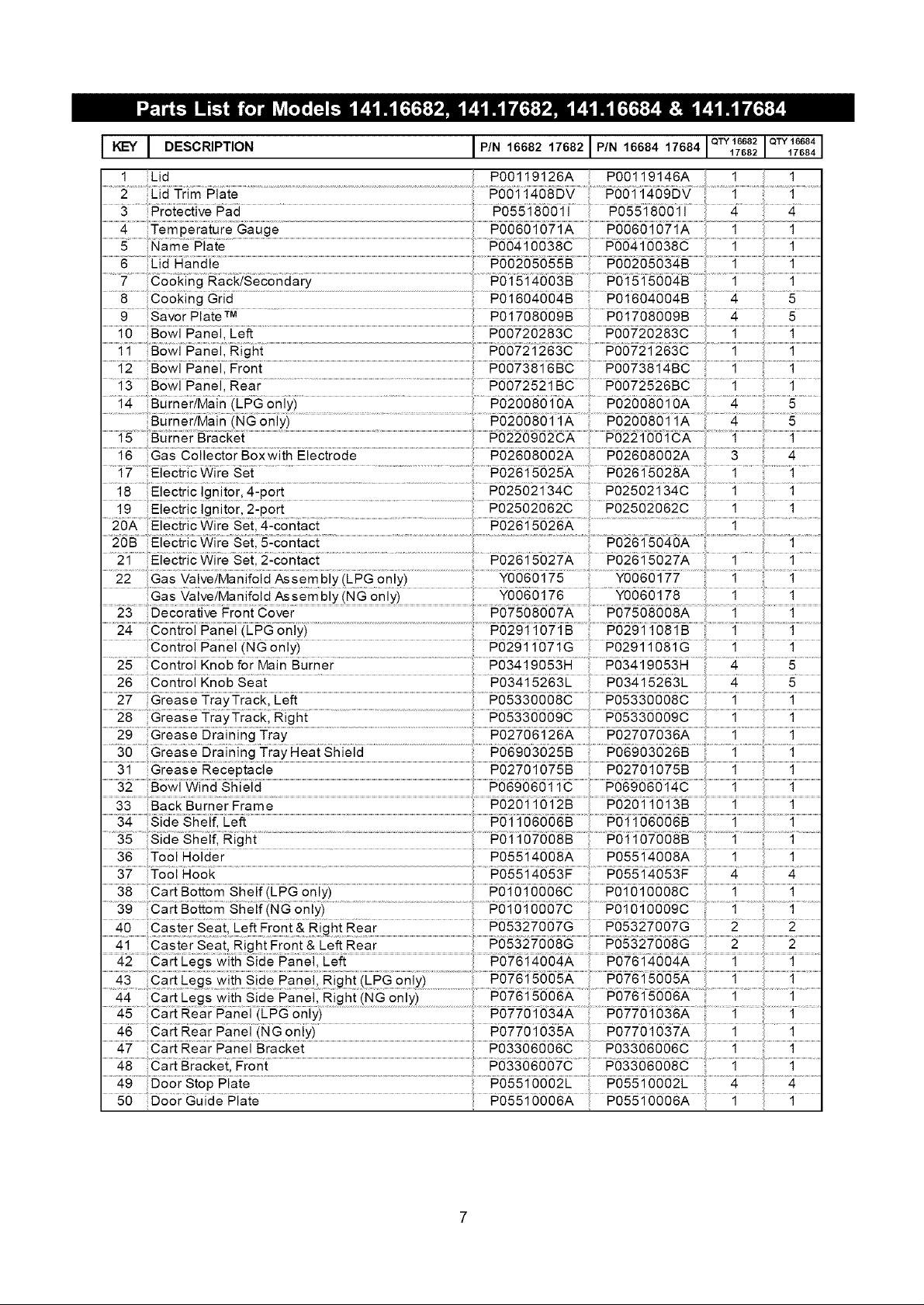
1 Lid P00119126A P00119146A 1 1
2 Lid Trim Plato P0011408DV P0011409DV 1 1
7 Cooking Rack/Secondary
8 Cooking Grid P01604004B P01604004B 4 5
Burner/Main (NG only) P02008011A P02008011A 4 5
QTY 16682 QTY 16684
................. Br_c_{ ......................................................................................................................................................................................................................................................................................................_ ........................._.........................................................._.............................
22 Gas ValvelManifold Assembly (LPG only) Y0060175 Y0060177 1 1
....................................................................................... Y0060176 .........Yo060178 1 1
24 Control Panel (LPG only) P02911071B P02911081B 1 1
26 Control Knob Seat P03415263L P03415263L
25 C°ntr°! Kn°b f°r Main Burner P03419053H P03419053H
27 Grease TrayTrack, Left P05330008C P05330008C
............... ht.............................................................................................................................................................................P05330009C ....................1.........................................................1.......................
30 Grease Draining TrayHeat Shield P06903025B P06903026B 1 1
35 Side Shelf, Right P01107008B P01107008B 1 1
39 CartBottom Shelf(NGonly) P01010007C P01010009C 1 1
.............................................................................................................................................................................................................................................................................................................................................................................................41 Castor Seat, Right Front & Left Rear ................................... ...................................2.........................i............................2.........................
49 Door Stop Plate P05510002L P05510002L 4 4
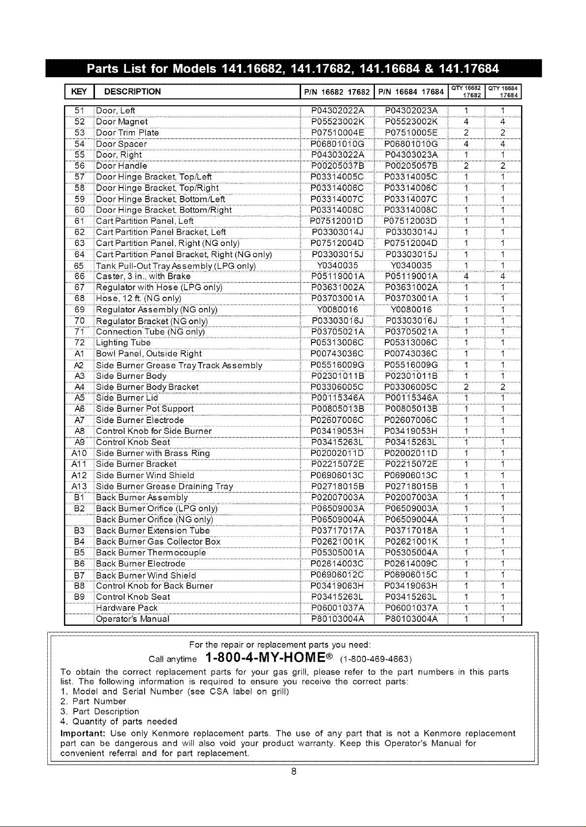
I I DESOR,PT,O. IP'N,60 2,..82IP,N,00.,7..I ,.682I ,.6641
51 Deer, Left P04302022A
52 Deer Magnet P05523002K P05523002K 4 4
QTY 16682 QTY 16684
53 .... P01510004E P01510005E .... 2....
58 Door Hinge Bracket, Top/Right P03314006C P03314006C 1 1
59 Door Hinge Bracketl Bottom/Eeft ....... P03314007c P033i4007c
................60 Door Hinge ........................................................................................................... ...........................................1........................................................1............................
62 Cart Partition Panel Bracket, Left P03303014J P03303014J 1 1
64 Cart Partition Panel Bracket, Right (NG only) P03303015J P03303015J 1 1
67 Regulator with Hose (LPG only) P03631002A P03631002A 1 1
on! i...................................................t 08 :0
70 Regulator Bracket (NG only) P03303016J P03303016J 1 1
A1 Bowl Panel, Outside Right P00743036C P00743036C 1 1
A2 Side Burner Grease TrayTrack Assembly P05516009G P05516009G 1 1
A3 Side Burner Body ..... P0230i 011B P0230i 0;1 ;1B......... 1......
.............A4 deB u rner Body B racket ..................................................................................................................................................................................................................#03 ......................................2....................................................2..........................
A6 Side Burner Pot Support P00805013B P008050"I3B 1
A7 Side Burner Electrode P02607006C P02607006C 1 1
A8 Control Knob for SideBurner ..... Po3419053H ;1 ;1
................ ...........................................................................................................................................................................................................................................................................................................................................;1..........................................................;1............................
A10 Side Burnerwith Brass Ring P02002011D P02002011D
........ .............................................................................................................................................................................................................................................................# ...............
Burner Wina Shieid ...................................................................................................................................................#069060 .......................1...............................1...............
...............B2 Back Burner ori{ice (LPG oniyi ........................................................................................................................................................ ..........................................;1........................................................;1............................
B3 Back Burner Extension Tube P03717017A P03717018A 1 1
B4 Back Burner Gas Collector Box P02621001K #0262;100;1K ;1 .........;1
B8 Control Knob for Back Burner P03419063H P03419063H 1 1
Operator's Manual
For the repair or replacement parts you need:
Ca_anytime1-800-4-MY-HOME® (1-800-469-4663)
To obtain the correct replacement parts for your gas grill, please refer to the part numbers in this parts
list. The following information is required to ensure you receive the correct parts:
1. Model and Serial Number (see CSA label on grill)
2. Part Number
3. Part Description
4. Quantity of parts needed
Important: Use only Kenmore replacement parts. The use of any part that is not a Kenmore replacement
part can be dangerous and will also void your product warranty. Keep this Operator's Manual for
convenient referral and for part replacement.
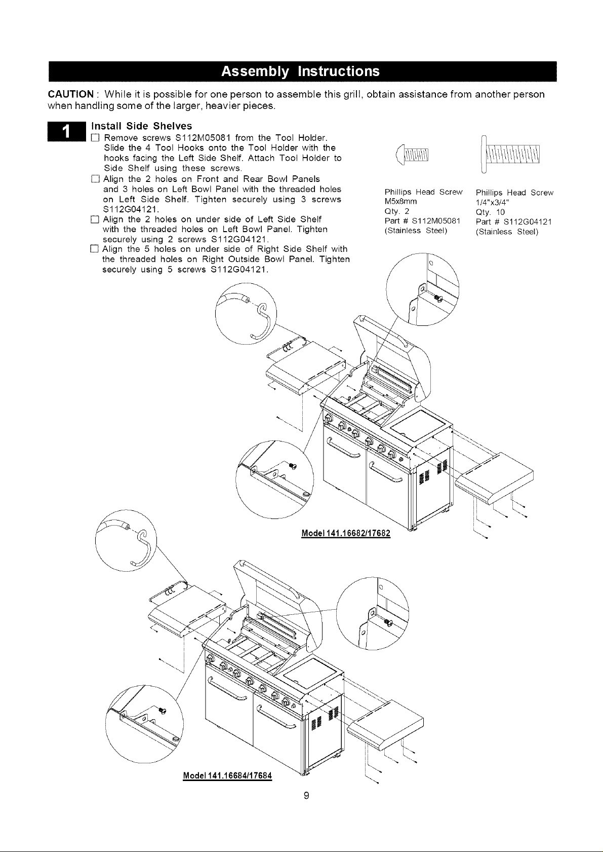
CAUTION " While it is possible for one person to assemble this grill, obtain assistance from another person
when handling some of the larger, heavier pieces.
Install Side Shelves
[] Remove screws $112M05081 from the Tool Holder.
Slide the 4 Tool Hooks onto the Tool Holder with the
hooks facing the Left Side Shelf. Attach Tool Holder to
Side Shelf using these screws.
[] Align the 2 holes on Front and Rear Bowl Panels
and 3 holes on Left Bowl Panel with the threaded holes
on Left Side Shelf. Tighten securely using 3 screws
$112G04121.
[] Align the 2 holes on under side of Left Side Shelf
with the threaded holes on Left Bowl Panel. Tighten
securely using 2 screws $112G04121.
[] Align the 5 holes on under side of Right Side Shelf with
the threaded holes on Right Outside Bowl Panel. Tighten
securely using 5 screws $112G04121.
Phillips Head Screw
MSx8mm
Qty. 2
Part # $112M05081
(Stainless Steel)
Phillips Head Screw
1/4"x3/4"
Qty. 10
Part # $112G04121
Stainless Steel)
i
i
Model 141.16662/17682
Model141.16664/17664
 Loading...