

Kenmore 141.16691 Owner's Manual
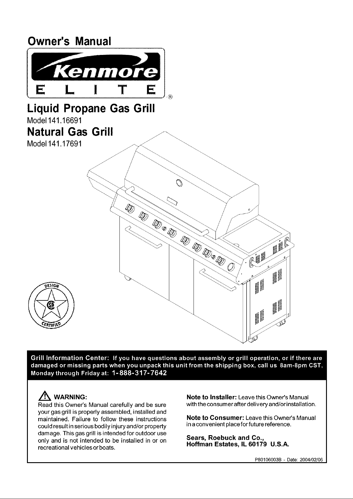
Owner's Manual
i T
Liquid Propane Gas Grill
Model141.16691
Natural Gas Grill
Model141.17691
®
A WARNING:
Read this Owner's Manual carefully and be sure
your gas grill is properly assembled, installed and
maintained. Failure to follow these instructions
could result in serious bodily injury and/or property
damage. This gas grill is intended for outdoor use
only and is not intended to be installed in or on
recreational vehicles or boats.
Note to Installer: Leave this Owner's Manual
withthe consumer after delivery and/or installation.
Note to Consumer: Leave this Owner's Manual
in aconvenient place for future reference.
Sears, Roebuck and Co.,
Hoffman Estates, IL 60179 U.S.A.
P80106003B - Date: 2004/02/06
Warranty ..................................................... 2
Safety Instructions ..................................... 2
Hardware .................................................... 6
Parts Diagram and Lists ........................ 7
Assembly Instructions .............................. 10
Lighting Instructions ................................ 16
Cleaning and Maintenance Instructions .... 18
Frequently Asked Questions .................. 20
Cooking Instructions .............................. A-1
Cooking Guide and Recipes .............. A-2
For the Lifetime of this Kenmore Elite Grill, Sears
willrepair orreplace, at ouroption, any Exterior
Stainless Steel or Aluminum Casting Parts (except for
paint loss).
Full 2-Year Warranty on Grill:
For 2years from the date of purchase Sears willrepair
or replace, at our option, any grill part (except for paint
loss, rusting and ignitor battery) that is defective in
material or workmanship.
Limited 3 Year Warranty on Selected Grill Parts:
From 2 years after the date of purchase for a 3-year
period, Searswill replace Flame Tamers, Cooking
Grids, Burners and All Other Parts (except for ignitor
battery) if they are defective in material or workman-
ship. You will be charged for labor.
Warranty Service
Warranty service is available by contacting the ®
nearest Sears Service Center at 1-80O-4-MY-HOME
Warranty Restrictions
• This warranty is void if grill is used for com-
mercial or rental purposes.
• This warranty applies only when the grill is
used in the United States.
• This warranty gives you specific legal rights,
and you may also have other rights which vary
from state to state.
Sears, Roebuck and Co., Dept. 817WA,
Hoffman Estates, IL 60179
Z_WARNING
Combustion byproducts produced when using
this product contain chemicals known to the
State of California to cause cancer, birth
defects, or other reproductive harm.
Z_WARNING
Failure to comply with these instructions
could result in a fire or explosion that
could cause serious bodily injury, death, or
property damage.
Z_WARNING
Your grill will get very hot. Never lean over
the cooking area while using your grill. Do not
touch cooking surfaces, grill housing, Lid or any
other grill parts while the grill is in operation, or
until the grill has cooled down after use.
Failure to comply with these instructions
may result in serious bodily injury.
Z_WARNING
(a) Do not store a spare LP-gas cylinder
under or near this appliance;
(b) Never fill the cylinder beyond 80 percent
full; and
(c) If the information in "(a)" and "(b)" is not
followed exactly, a fire causing death or
serious injury may occur.
FOR YOUR SAFETY
1. Do not store or use gasoline or other flam-
mable material and liquids in the vicinity of this
or any other appliance.
2. ALP cylinder not connected for use must not
be stored in the vicinity of this or any other
appliance.
FOR YOUR SAFETY
If you smell gas:
1. Shut off gas to the appliance.
2. Extinguish any open flame such as candle,
cigarette, lighter, etc., that could cause gas to
ignite.
3. Open the Grill Lid.
4. If odor continues, immediately call your gas
supplier or your fire department.
IMPORTANT: Your Kenmore LP Gas Grill cannot
be converted to use Natural Gas. Attempting to do
so is extremely hazardous and will also void the
grill warranty.
Grill Installation Codes
The installation must conform with local codes or, in
the absence of local codes, with either the National
Fuel Gas Code, ANSI Z223.1/NFPA 54, or CAN/
CGA-B14g.1, Natural Gas and Propane Installation
Code.
2 © Sears, Roebuck and Co.
Correct LP Gas Tank Use
LP gas grill models are designed for use with a
standard 20 lb. Liquid Propane Gas (LP gas) tank,
not included in grill box. Never connect your gas
_ritl to an LP gas tank that exceeds this capacity.
tank of approximately 12 inches in diameter by
18-1/2 inches high is the maximum size LP gas
tank to use. You must use an "OPD" gas tank
which offers a listed Overfill Prevention Device.
This safety feature prevents tank from being overfltled
which can cause malfunction of LP gas tank,
regulator and/or grill.
The LP gas tank must be constructed and marked
in accordance with the Specifications for LP-Gas
Cylinders of the U.S. Department of Transportation
(D.O.T.) or the National Standard of Canada, CAN/
CSA-B339, Cylinders, Spheres and Tubes for Trans-
portation of Dangerous Goods; and Commission, as
applicable.
1. The LP gas tank has a shutoff valve, termi-
nating in an LP gas supply tank valve outlet,
that is compatible with a Type 1 tank con-
nection device. The LP gas tank must also
have a safety relief device that has a direct
connection with the vapor space of the tank.
2. The tank supply system must be arranged
for vapor withdrawal.
3. The LP gas tank used must have a collar
to protect the tank valve.
• LP gas tanks must be stored outdoors in a
well-ventilated area and out of the reach of
children. Disconnected LP gas tanks must not
be stored in a building, garage or any other
enclosed area.
• When your gas grill is not in use the gas
must be turned off at the LP gas tank.
• The regulator and hose assembly can be seen
after opening the doors (if applicable), must be
inspected before each use of the grill. If there
is excessive abrasion or wear or if the hose is
cut, it must be replaced prior to the grill being
used again.
• Keep the gas regulator hose away from hot
grill surfaces and dripping grease. Avoid unnec-
essary twisting of hose. Visually inspect hose
prior to each use for cuts, cracks, excessive
wear or other damage. If the hose appears
damaged do not use the gas grill. Call Sears
at 1-800-4-MY-HOME ®(1-800-469-4663) for a
Sears authorized replacement hose.
• Never light your gas grill with the lid closed or
before checking to ensure the burner tubes are
fully seated over the gas valve orifices.
• Never allow children to operate your grill. Do
not allow children to play near your grill.
Proper Placement and Clearance of Grill
Never use your gas grill in a garage, porch, shed,
breezeway or any other enclosed area. Your gas grill is
to be used outdoors only, at least 24 inches from the
back and side of any combustible surface. Do not
locate this appliance underoverhead unprotected
combustible surfaces. Do not obstruct the flow of
ventilation air around the gasgrill housing.
This outdoor gas grill is not intended to be installed in
or on recreational vehicles and/or boats.
• Never connect an unregulated LP gas tank to
your gas grill. The gas regulator assembly
supplied with your gas grill is adjusted to have
an outlet pressure of 11" water column (W.C.)
for connection to an LP gas tank.
• Only use the regulator and hose assembly
supplied with your gas grill. Replacement
regulators and hose assemblies must be those
specified by Sears.
• Have your LP gas tank filled by a reputable
propane gas dealer and visually inspected and
re-qualified at each filling.
• Never fill the gas tank beyond 80% full.
Have your propane gas dealer check the
release valve after every filling to ensure that it
remains free of defects.
• Always keep LP gas tanks in upright position.
Do not store (or use) gasoline or other flammable
vapors and liquids in the vicinity of this gas grill.
• LP gas tanks not connected for use must NOT be
stored on bottom shelf or in the vicinity of this or
any other gas grill.
• Do not subject the LP gas tank to excessive heat.
• Never store an LP gas tank indoors. If you
store your gas grill in the garage or other indoor
location, always disconnect the LP gas tank
first and store it safely outside.
,4kWARNING
If you smell gas:
• Shut off gas supply to the gas grill.
• Turn the Control Knobs to OFF position.
• Extinguish any open flame such as candle,
cigarette, lighter, etc., that could cause gas
to ignite.
• Open the Grill Lid.
• Get away from the LP gas tank.
• Do not try to fix the problem yourself.
• If odor continues or you have a fire you
cannot extinguish, call your fire depart-
ment. Do not call near the LP gas tank
because your telephone is an electrical
device and could create a spark resulting
in fire and/or explosion.
NOTE: The normal flow of gas through the
regulator and hose assembly can create a
humming noise. A low volume of noise is
perfectly normal and will not interfere with
operation of the grill. If humming noise is
loud and excessive you may need to purge
air from the gas line or reset the regulator
excess gas flow device. This purging proce-
dure should be done every time a new LP
gas tank is connected to your grill. For help
call the Grill Information Center for assis-
tance, 8am - 8pm CST, Monday through
Friday 1-888-317-7642.
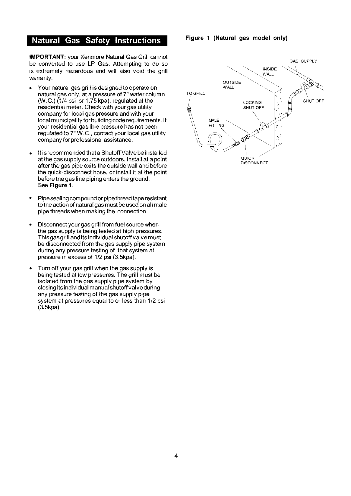
Figure 1 (Naturalgas model only)
IMPORTANT: your Kenmore Natural Gas Grill cannot
be converted to use LP Gas. Attempting to do so
is extremely hazardous and will also void the grill
warranty.
Your natural gas grill isdesigned to operate on
natural gas only, at a pressure of 7" water column
(W.C.) (1/4 psi or 1.75 kpa), regulated at the
residential meter. Check with your gas utility
company for local gas pressure and with your
local municipality for building code requirements. If
your residential gas line pressure has not been
regulated to 7" W.C., contact your local gas utility
company for professional assistance.
It is recom mended that a Shutoff Valve be installed
at the gas supply source outdoors, install at a point
after the gas pipe exits the outside wall and before
the quick-disconnect hose, or install it at the point
before the gas line piping enters the ground.
See Figure 1.
• Pipe sealing com pound or pipe thread tape resistant
to the action of natural gas must be used on all male
pipe threadswhen making the connection.
Disconnect your gas grill from fuel source when
the gas supply is being tested at high pressures.
Thisgasgrill and its individual shutoffvalve must
be disconnected from the gas supply pipe system
during any pressure testing of that system at
pressure in excess of 1/2 psi (3.5kpa).
TO GRILL
MALE
F_TTING
OUTSIDE
WALL
LOCKING
SHUT OFF
\
\
\
\
\
J
QUICK
DISCONNECT
GAS SUPPLY
INSIDE
WALL
SHUT OFF
J
Turn off your gas grill when the gas supply is
being tested at low pressures. The grill must be
isolated from the gas supply pipe system by
closing itsindividual manual shutoff valve during
any pressure testing of the gas supply pipe
system at pressures equal to or less than 1/2 psi
(3.5kpa).
4
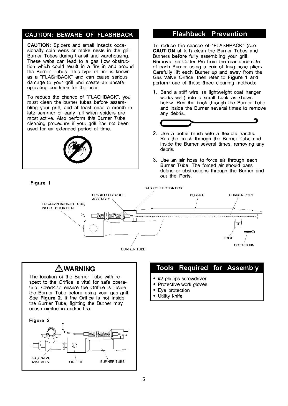
CAUTION:Spidersandsmallinsectsocca-
sionallyspinwebsor makenestsin the grill
BurnerTubesduringtransitandwarehousing.
Thesewebscanleadto a gasflowobstruc-
tionwhichcouldresultin a fire in andaround
theBurnerTubes.Thistypeof fire is known
as a "FLASHBACK"and cancauseserious
damageto yourgrill andcreateanunsafe
operatingconditionfor theuser.
To reducethe chanceof "FLASHBACK",you
mustcleanthe burnertubesbeforeassem-
blingyourgrill, andat leastoncea monthin
latesummeror earlyfall whenspidersare
mostactive.AlsoperformthisBurnerTube
cleaningprocedureif yourgrillhasnotbeen
usedfor an extendedperiodof time.
Figure 1
SPARKELECTRODE
TO CLEAN BURNER TUBE,
INSERT HOOK HERE
ASSEMBLY \\
\\
To reduce the chance of "FLASHBACK" (see
CAUTION at left) clean the Burner Tubes and
Burners before fully assembling your grill.
Remove the Cotter Pin from the rear underside
of each Burner using a pair of long nose pliers.
Carefully lift each Burner up and away from the
Gas Valve Orifice, then refer to Figure 1 and
perform one of these three cleaning methods:
.
Bend a stiff wire, (a lightweight coat hanger
works well) into a small hook as shown
below. Run the hook through the Burner Tube
and inside the Burner several times to remove
any debris.
[ J
.
Use a bottle brush with a flexible handle.
Run the brush through the Burner Tube and
inside the Burner several times, removing any
debris.
.
Use an air hose to force air through each
Burner Tube. The forced air should pass
debris or obstructions through the Burner and
out the Ports.
GAS COLLECTOR BOX
BURNER BURNER PORT
\
BURNER TUBE
Z WARNING
The location of the Burner Tube with re-
spect to the Orifice is vital for safe opera-
tion. Check to ensure the Orifice is inside
the Burner Tube before using your gas grill.
See Figure 2. If the Orifice is not inside
the Burner Tube, lighting the Burner may
cause explosion and/or fire.
Fiqure 2
GASVALVE / \
ASSEMBLY ORIFICE BURNER TUBE
\
I
FOOT
COTTER PIN
• #2 phillips screwdriver
• Protective work gloves
• Eye protection
• Utility knife
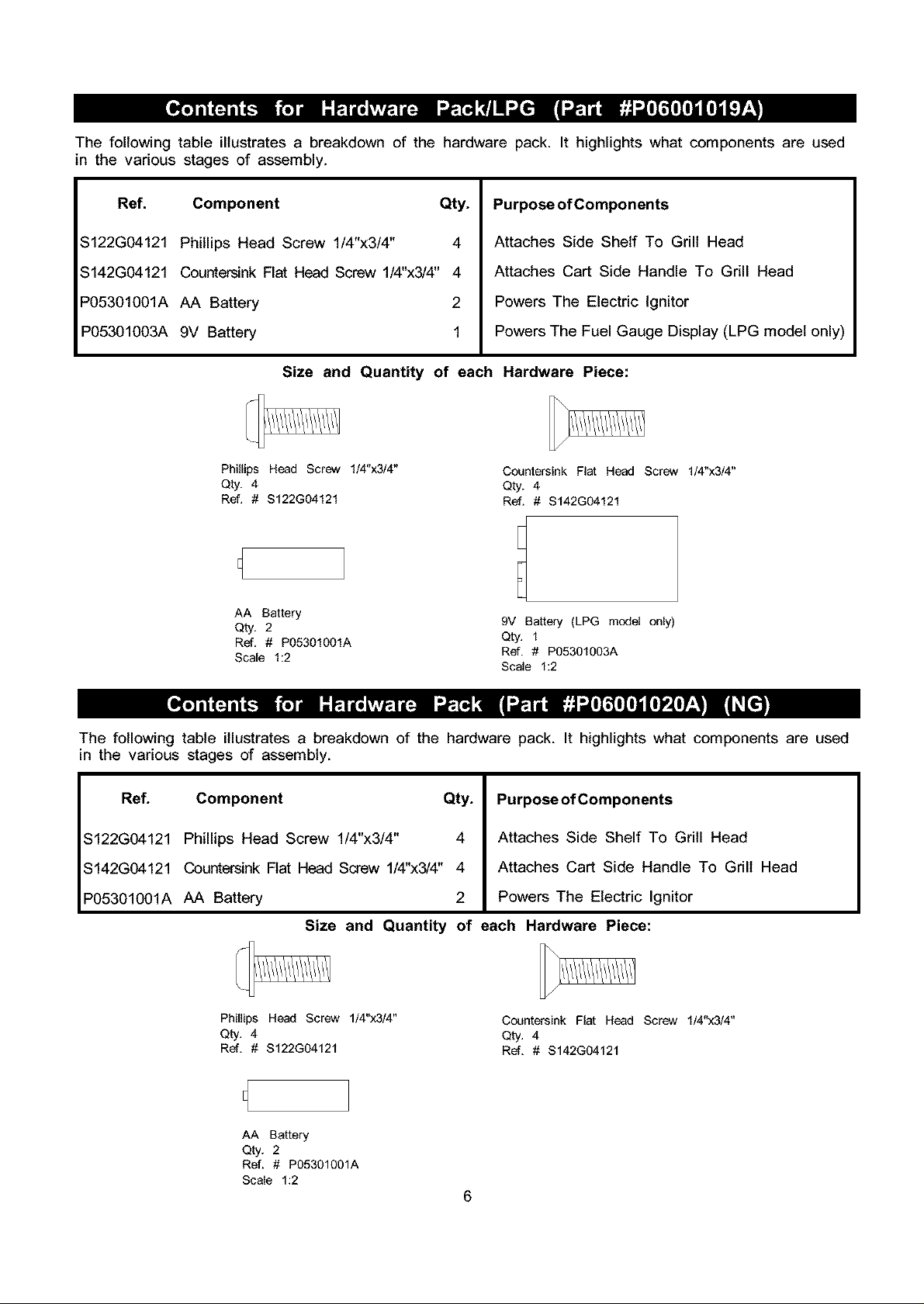
Thefollowingtableillustratesa breakdownof thehardwarepack.It highlightswhatcomponentsare used
in the variousstagesof assembly.
Ref. Component Qty.
$122G04121 Phillips Head Screw 1/4"x3/4" 4
$142G04121 Countersink Flat Head Screw 1/4"x3/4" 4
P05301001A AA Battery 2
P05301003A 9V Battery 1
Size and Quantity of each Hardware Piece:
Phillips Head Screw 1/4"x3/4"
Qty. 4
Ref. # $122G04121
AA Battery
Qty. 2
Ref, # P05301001A Qty. 1
Scale 1:2 Ref. # P05301003A
Purpose of Components
Attaches Side Shelf To Grill Head
Attaches Cart Side Handle To Grill Head
Powers The Electric Ignitor
Powers The Fuel Gauge Display (LPG model only)
Countersink Fiat Head Screw 1/4"x3/4"
Qty. 4
Ref. # $142G04121
9V Battery (LPG model only)
Scale 1:2
The following table illustrates a breakdown of the hardware pack. It highlights what components are used
in the various stages of assembly.
Ref. Component Qty.
$122G04121 Phillips Head Screw 1/4"x3/4" 4
$142G04121 Countersink Flat Head Screw 1/4"x3/4" 4
P05301OO1A AA Battery 2
PurposeofComponents
Attaches Side Shelf To Grill Head
Attaches Cart Side Handle To Grill Head
Powers The Electric Ignitor
Size and Quantity of each Hardware Piece:
Phillips Head Screw 1/4"x3/4"
Qty. 4
Ref. # $122G04121
AA Battery
Qty. 2
Ref. # P05301001A
Scale 1:2
Countersink Flat Head Screw 1/4"x3/4"
Qty. 4
Ref. # $142G04121
6
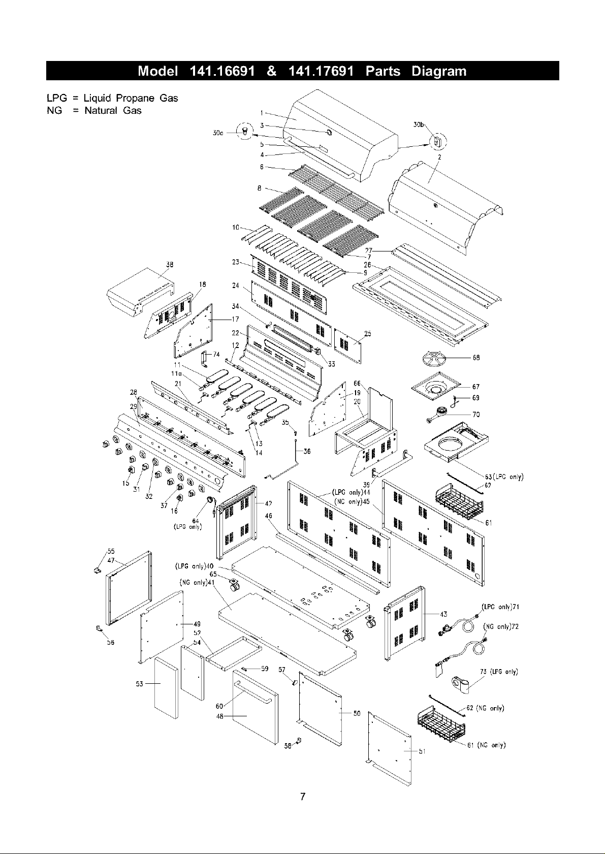
LPG = Liquid Propane Gas
NG = Natural Gas
38 23_
28
30b\
18 24
36
Ib
31
32 /
37
16
(LPGonly)
(LPG only)40
64
65_
(NG only)41
_59 57
_(LPG only144
3_
|i
] _43 (LP¢ only)71
(NG only)72
__7_ (LPGonly)
bl
7
PEP# DESCRIPTION
1 Lid
2 Lid Trim Plate
3 Temperature Gauge
4 Lid Handle
5 Name Plate
6 Cooking Rack/Secondary
7 Cooking Grid/Large
8 Cooking Grid/Small
9 Flame Tamer/Large
10 Flame Tamer/Small
11 Burner/Main
1la Burner Air Shutter/Main (NG only)
12 Burner Bracket
13 Gas Collector Box with Electrode
14 Electric Wire Set
15 Electric Ignitor, 4-Ports
16 Electric Ignitor, 2-Ports
17 Bowl Panel, Left
18 Bowl Panel, Outside Left
19 Bowl Panel, Right
20 Bowl Panel, Outside Right
21 Bowl Panel, Front
22 Bowl Panel, Rear
23 Bowl Wind Shield, Upper
24 Bowl Wind Shield, Lower Left
25 Bowl Wind Shield, Lower Right
26 Grease Draining Tray
27 Grease Draining Tray Heat Shield
28 Gas Valve/Manifold Assembly (LPG)
Gas Valve/Manifold Assembly (NG)
29 Control Panel (LPG)
Control Panel (NG)
30a Protective Pad, Lid Front
30b Protective Pad, Lid Rear
31 Control Knob for Main/Side Burners
32 Control Knob Seat
33 Back Burner Assembly
34 Back Burner Electrode
35 Back Burner Orifice (LPG)
Back Burner Orifice (NG)
36 Back Burner Extension Tube
37 Control Knob for Back Burner
38 Side Shelf, Left
39 Cart Side Handle
40 Cart Bottom Shelf (LPG only)
41 Cart Bottom Shelf (NG only)
42 Cart Legs with Side Panel, Left
43 Cart Legs with Side Panel, Right
44 Cart Rear Panel (LPG only)
45 Cart Rear Panel (NG only)
46 Door Bracket
47 Door, Left
48 Door, Right
8
PART#
P0011903AA
P0011435EA
P00601171A
P00205033B
P00410038C
P01518001B
P01606032B
P01606033B
P01708031B
P01708032B
P02001004E
P05524004A
P02206271B
P02608050C
P02615053A
P02502024C
P02502012C
P00720293C
P00742296C
P00721293C
P00743296C
P00738303C
P00725303C
P00737303C
P06906005C
P06906007C
P02714012F
P06903009D
Y0060083
Y0060131
P02911291N
P02911291T
P055181001
P055180041
P03419033H
P03415264A
P02007049D
P02614006B
P06509010A
P06509016A
P03717033A
P03419043H
P01106028B
P00205032B
P01005026H
P01005034H
P07614001A
P07615001A
P07701021A
P07701022A
P03302007C
P04302012A
P04303012A
QTY
1
1
1
1
1
1
3
1
3
1
6
6
1
3
1
1
1
1
1
1
1
1
1
1
1
1
1
1
1
1
1
1
2
2
7
8
1
1
1
1
1
1
1
1
1
1
1
1
1
1
1
1
1
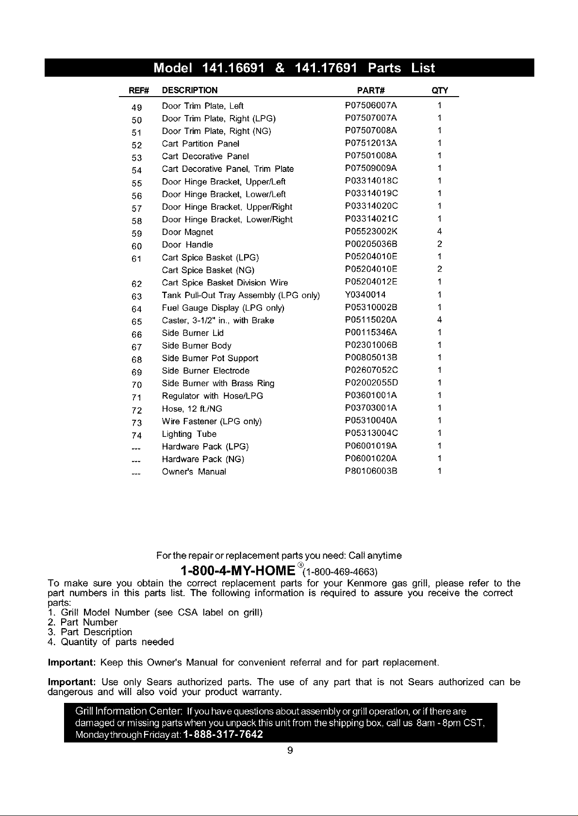
FIEF#DESCRIPTION PART# QTY
49 Door Trim Plate, Left P07506007A 1
50 Door Trim Plate, Right (LPG) P07507007A 1
51 Door Trim Plate, Right (NG) P07507008A 1
52 Cart Partition Panel P07512013A 1
53 Cart Decorative Panel P07501008A 1
54 Cart Decorative Panel, Trim Plate P07509009A 1
55 Door Hinge Bracket, UppedLeft P03314018C 1
56 Door Hinge Bracket, Lower/Left P03314019C 1
57 Door Hinge Bracket, UppedRight P03314020C 1
58 Door Hinge Bracket, Lower/Right P03314021C 1
59 Door Magnet PO5523002K 4
60 Door Handle PO0205036B 2
61 Cart Spice Basket (LPG) PO5204010E 1
Cart Spice Basket (NG) PO5204010E 2
62 Cart Spice Basket Division Wire PO5204012E 1
63 Tank Pull-Out Tray Assembly (LPG only) Y0340014 1
64 Fuel Gauge Display (LPG only) PO531O002B 1
65 Caster, 3-1/2" in., with Brake P0511502OA 4
66 Side Burner Lid P00115346A 1
67 Side Burner Body PO2301006B 1
68 Side Burner Pot Support PO0805013B 1
69 Side Burner Electrode P02607052C 1
70 Side Burner with Brass Ring PO2002055D 1
71 Regulator with Hose/LPG P03601001A 1
72 Hose, 12 ft./NG P03703001A 1
73 Wire Fastener (LPG only) P0531004OA 1
74 Lighting Tube P05313004C 1
... Hardware Pack (LPG) P06O01019A 1
... Hardware Pack (NG) P0600102OA 1
... Owner's Manual PS0106003B 1
For the repair or replacement parts you need: Call anytime
1-800-4-MY-HOME 1-800-46g-4663)
To make sure you obtain the correct replacement parts for your Kenmore gas grill, please refer to the
part numbers in this parts list. The following information is required to assure you receive the correct
parts:
1. Grill Model Number (see CSA label on grill)
2. Part Number
3. Part Description
4. Quantity of parts needed
Important: Keep this Owner's Manual for convenient referral and for part replacement.
Important: Use only Sears authorized parts. The use of any part that is not Sears authorized can be
dangerous and will also void your product warranty.
9
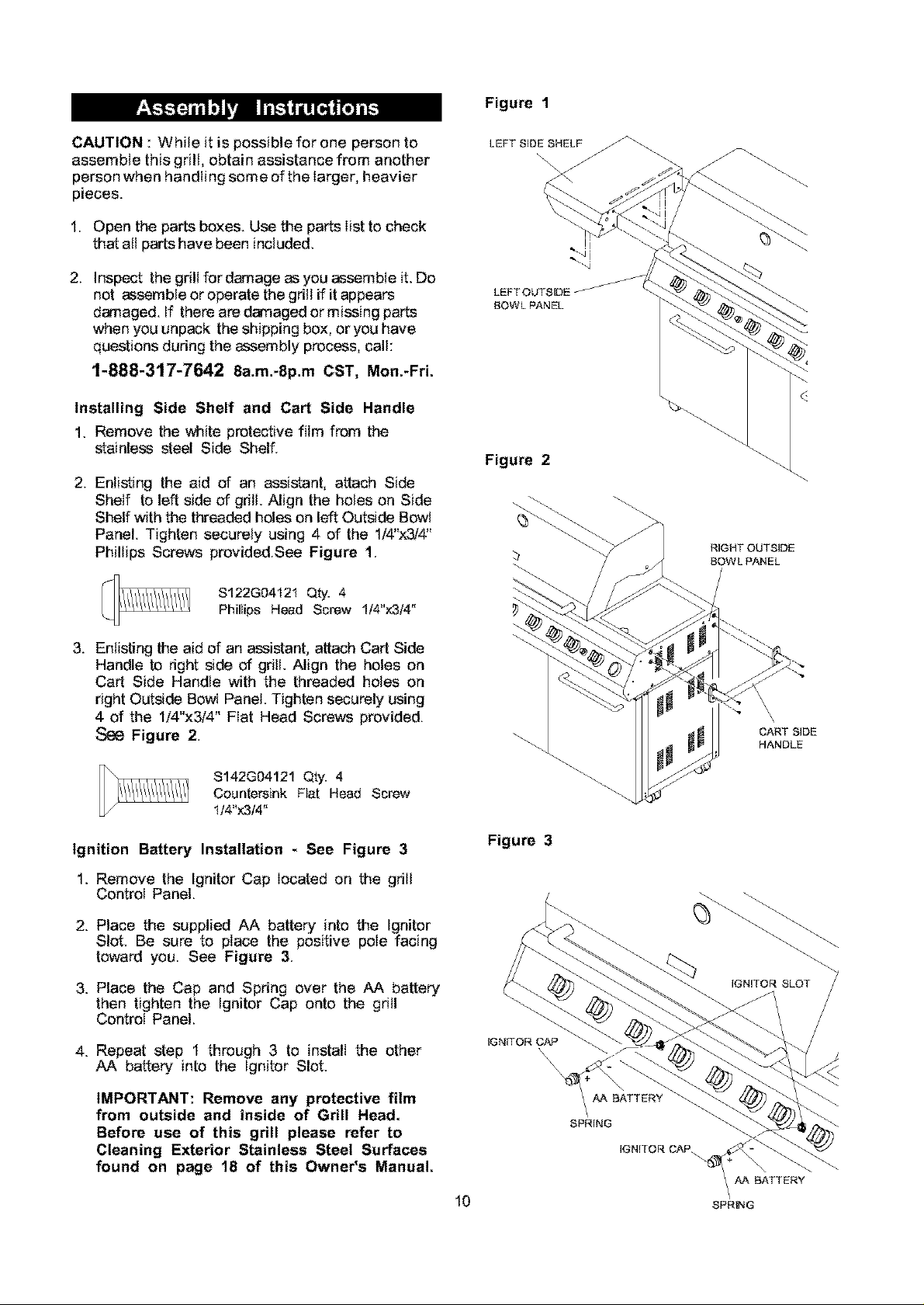
CAUTION : While it is possible for one person to
assemble this grill, obtain assistance from another
person when handling some of the larger, heavier
pieces.
1. Open the parts boxes. Use the parts list to check
that all parts have been included.
Figure 1
-..Ai
2. Inspect the grill fordamage as you assemble it. Do
not assemble or operate the gdlt if it appears
damaged. If there are damaged or missing parts
when you unpack the shipping box, or you have
questions dudng the assembly process, call:
1-888-317-7642 8a.m.-8p.m CST, Mon.-FrL
Installing Side Shelf and Cart Side Handle
1. Remove the white protective film from the
stainless steel Side Shelf.
2. Enlisting the aid of an assistant, attach Side
Shelf to left side of grill. Align the holes on Side
Shelf with the threaded holes on left Outside Bowl
Panel. Tighten securely using 4 of the 1/4"x3/4"
Phillips Screws provided.See Figure 1.
S122G04t21 Qty. 4
Phillips Head Screw 1/4"x3/4"
3. Enlisting the aid of an assistant, attach Cart Side
Handle to right side of grill. Align the holes on
Cart Side Handle with the threaded holes on
right Outside Bowl Panel. Tighten securely using
4 of the 1/4"x3/4" Fiat Head Screws provided.
Figure 2.
LEFT OUTSIDE
BOWL PANEL
Figure 2
RIGHT OUTSIDE
BOWL PANEL
CART SIDE
HANDLE
$142G04121 Qty. 4
Countersink Fiat Head Screw
1/4"x3/4"
Ignition Battery Installation - See Figure 3
1. Remove the Ignitor Cap located on the grill
Control Panel.
2. Place the supplied AA battery into the Ignitor
Slot. Be sure to place the positive pole facing
toward you. See Figure 3.
3. Place the Cap and Spring over the AA battery
then tighten the Ignitor Cap onto the grill
Control Panel.
4. Repeat step 1 through 3 to install the other
AA battery into the Ignitor Slot.
IMPORTANT: Remove any protective film
from outside and inside of Grill Head.
Before use of this grill please refer to
Cleaning Exterior Stainless Steel Surfaces
found on page 18 of this Owner's Manual.
10
Figure 3
IGNITOR SLOT
IGNITOR CAP
\\\\\
AA BATTERY
SPRING
IGNITOR CAP.
AA BATTERY
SPRING
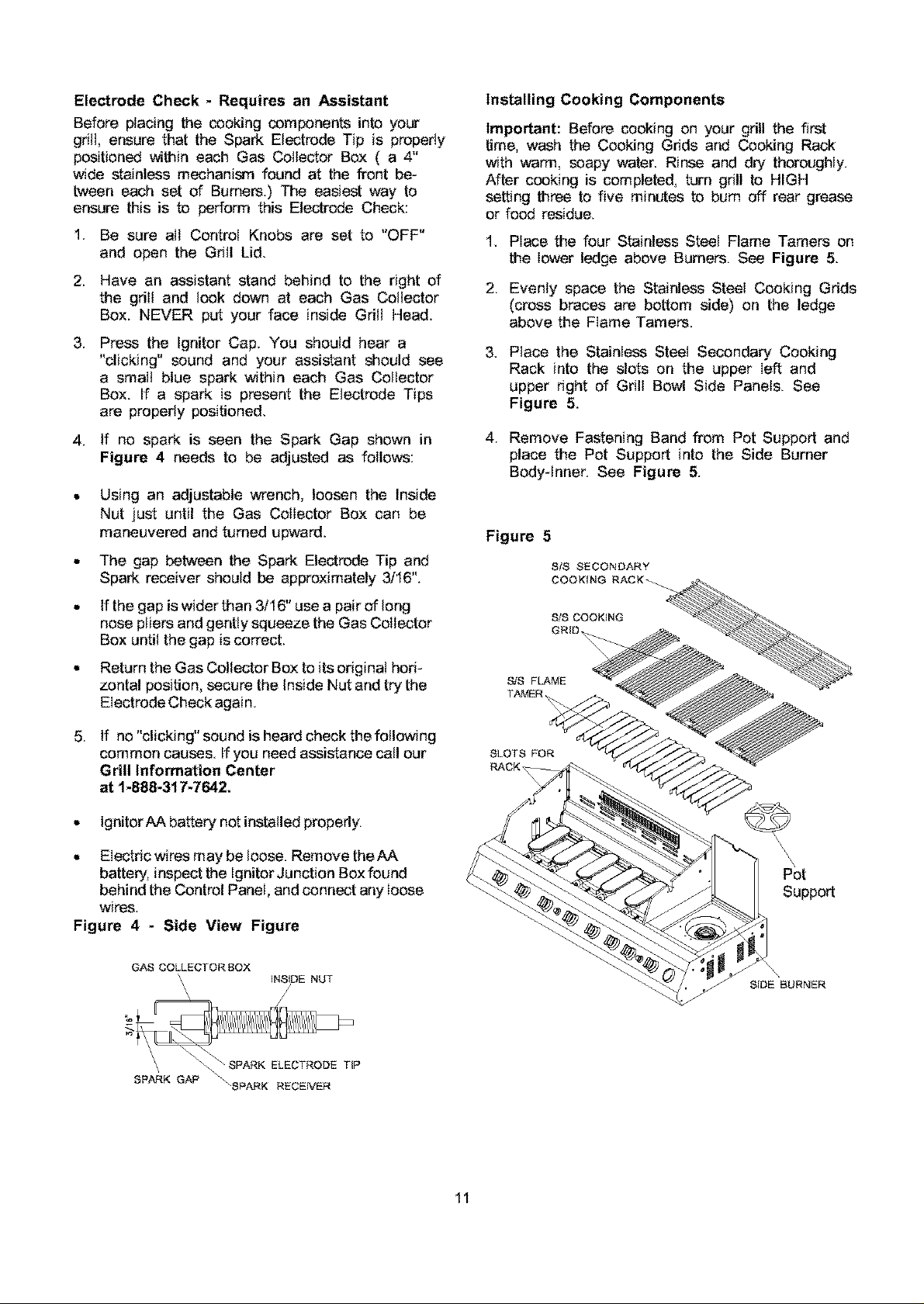
Electrode Check - Requires an Assistant
Before placing the cooking components into your
grill, ensure that the Spark Electrode Tip is properly
positioned within each Gas Collector Box ( a 4"
wide stainless mechanism found at the front be-
tween each set of Burners.) The easiest way to
ensure this is to perform this Electrode Check:
1. Be sure all Control Knobs are set to "OFF"
and open the Grill Lid.
2. Have an assistant stand behind to the right of
the grill and look down at each Gas Collector
Box. NEVER put your face inside Grill Head.
.
Press the Ignitor Cap. You should hear a
"clicking" sound and your assistant should see
a small blue spark within each Gas Collector
Box. If a spark is present the Electrode Tips
are properly positioned.
4. If no spark is seen the Spark Gap shown in
Figure 4 needs to be adjusted as follows:
Using an adjustable wrench, loosen the Inside
Nut just until the Gas Collector Box can be
maneuvered and turned upward.
Installing Cooking Components
Important: Before cooking on your grill the first
time, wash the Cooking Grids and Cooking Rack
with warm, soapy water. Rinse and dry thoroughly.
After cooking is completed, turn grill to HIGH
setting three to five minutes to bum off rear grease
or food residue.
1. Place the four Stainless Steel Flame Tamers on
the lower ledge above Burners. See Figure 5.
2. Evenly space the Stainless Steel Cooking Grids
(cross braces are bottom side) on the ledge
above the Flame Tamers.
.
Place the Stainless Steel Secondary Cooking
Rack into the slots on the upper left and
upper right of Grill Bowl Side Panels. See
Figure 5.
4. Remove Fastening Band from Pot Support and
place the Pot Support into the Side Burner
Body-Inner. See Figure 5.
The gap between the Spark Electrode Tip and
Spark receiver should be approximately 3/16".
If the gap is wider than 3/16" use a pair of long
nose pliers and gently squeeze the Gas Collector
Box until the gap is correct.
Return the Gas Collector Box to its original hori-
zontal position, secure the Inside Nut and try the
EIectrede Check again.
5_
If no "clicking" sound is heard check the following
common causes. If you need assistance call our
Grill Information Center
at 1-888-317-7642.
• IgnitorAA battery not installed property.
• Electric wires may be loose. Remove the AA
battery, inspect the Ignitor Junction Box found
behind the Control Panel, and connect any loose
wires.
Figure 4 - Side View Figure
GAS COLLECTOR BOX
'\ INSIDE NUT
SLS COOKbNG
GRID
S/S FLAME
TAMER
SLOTS FOR
RACK
Pot
Support
\
SIDE BURNER
SP_K G_"_ _SPARK RECEIVER
11
 Loading...