

Kenmore 141.163251, 141.163231, 141.163211 Owner's Manual
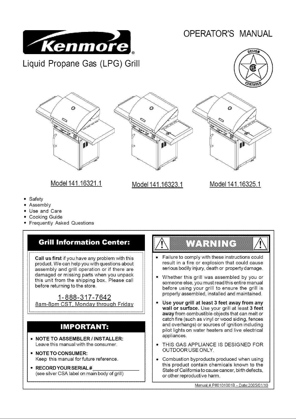
Liquid Propane Gas@(LPG) Grill
OPERATOR'S MANUAL
Model 141.16321.1
• Safety
• Assembly
• Use and Care
• Cooking Guide
• Frequently Asked Questions
Call us first if you have any problem with this
product. We can help you with questions about
assembly and grill operation or if there are
damaged or missing parts when you unpack
this unit from the shipping box. Please call
before returning to the store.
1-888-317-7642
8am-8pm CST, Monday throuqh Friday
• NOTE TO ASSEMBLER / INSTALLER:
Leave this manual with the consumer.
• NOTETO CONSUMER:
Keep this manual for future reference.
• RECORD YOURSERIAL #
(see silver CSA label on main body of grill)
Model 141.16323.1
Failure to comply with these instructions could
result in a fire or explosion that could cause
serious bodily injury, death or propertydamage.
Whether this grill was assembled by you or
someone else, you must read this entire manual
before using your grill to ensure the grill is
properly assembled, installed and maintained.
Use your grill at least 3 feet away from any
wall or surface. Use your grill at least 3 feet
away from combustible objects that can melt or
catch fire (such as vinyl or wood siding, fences
and overhangs) or sources of ignition including
pilot lights on water heaters and live electrical
appliances.
THIS GAS APPLIANCE IS DESIGNED FOR
OUTDOOR USE ONLY.
Combustion byproducts produced when using
this product contain chemicals known to the
State of California to cause cancer, birth defects,
or other reproductive harm.
Model141.16325.1
Manua! # P80101001B - Date:2005/01/10
Primary Safety Warnings ........................... 1-3
Warranty Terms and Conditions .................. 2
Pre-Assembly Instructions .............................. 3
Part Diagrams and Lists .......................... 4-9
Assembly Instructions ............................. 10-15
LP Gas Tank Installation ...................... 16-18
Use & Care Instructions:
• Lighting Instructions ................................. 19
• Troubleshooting .......................................... 20
Cleaning and Maintenance ..................... 21-22
Cooking Guide ........................................ A1-A6
Frequently Asked Questions ................ A7-A8
One-Year Full Warranty on Kenmore Grill
For one year from the date of purchase Sears will
repair this grill if it is defective in material or
workmanship.
If repair proves impossible, Sears will, at your option,
either replace this grill with a new one, or refund the
full purchase price.
This warranty excludes ignitor batteries and grill paint
loss or rusting, which are either expendable parts
that can wear out from normal use in less than a
year, or are conditions that can be the result of
normal use, accident or improper maintenance.
Limited Warranty on Selected Grill Parts
From one year after the date of purchase for
the designated time periods listed below,
Sears will replace the following grill parts if
they are defective in material or workmanship.
You will be charged for labor.
• Lifetime: Tube Burners and Stainless Steel parts
(except for discoloration due to normal use or
excessive heat, and scratches or dents caused
by normal use and improper maintenance).
• 2 Years: All Other Grill Parts (except Savor
Plates TM, cooking grids and ignitor battery)
Warranty Service
Warranty service is available by contacting
Sears at 1-800-4-MY-HOME ®
Warranty Restrictions
• This warranty is void if grill is used for
commercial or rental purposes.
• This grill is safety certified for use only in
the country where purchased. Modification for
use in any other location is a safety hazard
and will void the warranty.
• This warranty gives you specific legal rights,
and you may also have other rights which
vary from state to state.
Sears, Roebuck and Co., Dept. 817WA,
Hoffman Estates, IL 60179 U.S.A.
© Sears, Roebuck and Co.
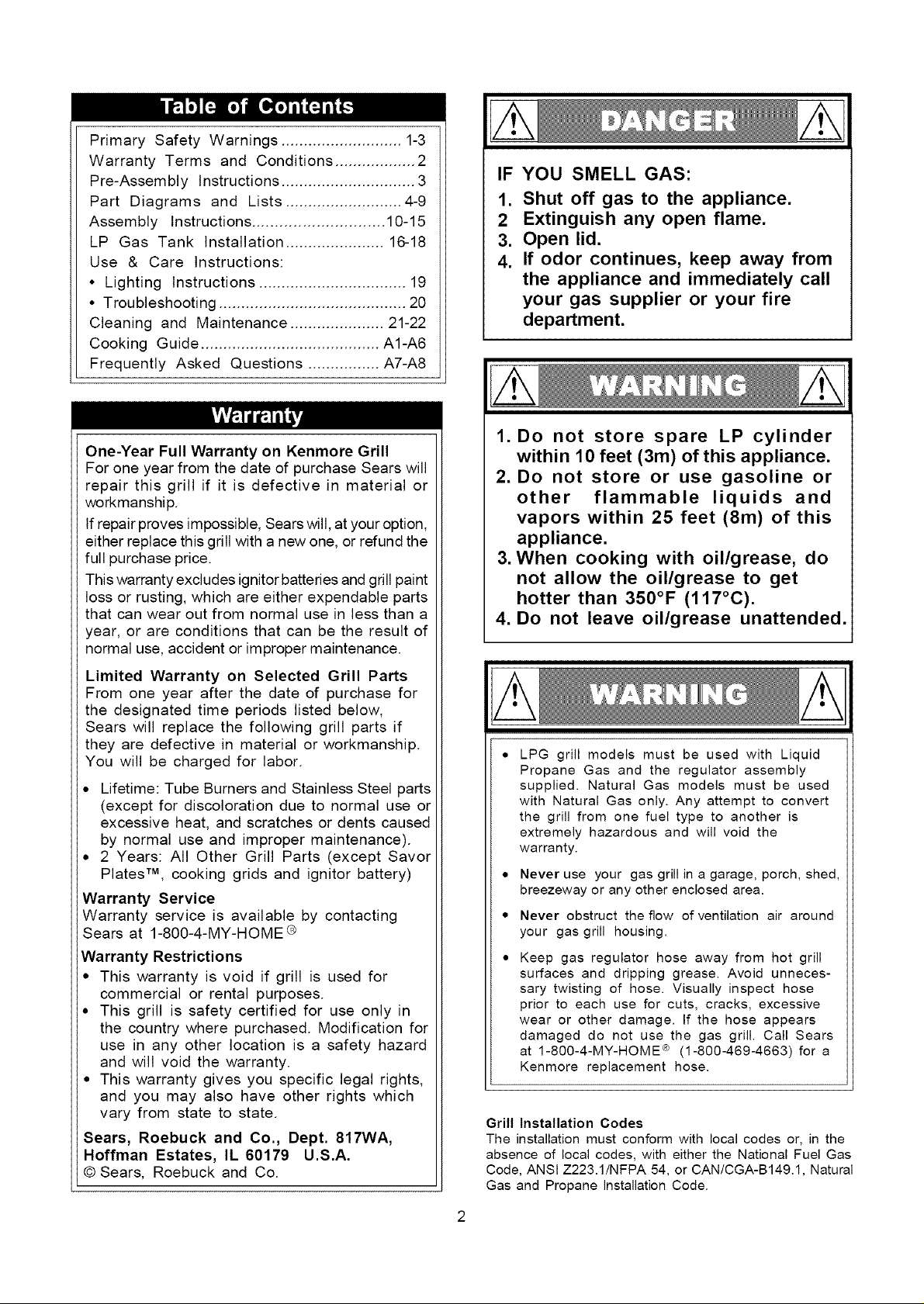
IF YOU SMELL GAS:
1. Shut off gas to the appliance.
2 Extinguish any open flame.
3. Open lid.
4. If odor continues, keep away from
the appliance and immediately call
your gas supplier or your fire
department.
1. Do not store spare LP cylinder
within 10 feet (3m) of this appliance.
2. Do not store or use gasoline or
other flammable liquids and
vapors within 25 feet (8m) of this
appliance.
3. When cooking with oil/grease, do
not allow the oil/grease to get
hotter than 350°F (117°C).
.
Do not leave oil/grease unattended.
LPG grill models must be used with Liquid
Propane Gas and the regulator assembly
supplied. Natural Gas models must be used
with Natural Gas only. Any attempt to convert
the grill from one fuel type to another is
extremely hazardous and will void the
warranty.
• Never use your gas grill in a garage, porch, shed,
breezeway or any other enclosed area.
• Never obstruct the flow of ventilation air around
your gas grill housing.
Keep gas regulator hose away from hot grill
surfaces and dripping grease. Avoid unneces-
sary twisting of hose. Visually inspect hose
prior to each use for cuts, cracks, excessive
wear or other damage. If the hose appears
damaged do not use the gas grill. Call Sears
at 1-800-4-MY-HOME _ (1-800-469-4663) for a
Kenmore replacement hose.
Grill Installation Codes
The installation must conform with local codes or, in the
absence of local codes, with either the National Fuel Gas
Code, ANSI Z223.1/NFPA 54, or CAN/CGA-B149.1, Natural
Gas and Propane installation Code.
Failure to comply with these instructions may
result in a hazardous situation which, if not
avoided, may result in injury,
Spiders and small insects can spin webs and
nest in the grill ing transit and
warehousing flow
obstruction round the
Burner T_ FIRE"
can cau_ ate an
unsafe €
To .'K
FIRE bes
as follc grill.
Also do _ummer
and fall or in your
area, and if used for an
extended perioc
1. Remove the screw from the rear of each Burner
using a Phillips Head Screwdriver.
2. Carefully lift each Burner up and away from the
Gas Valve Orifice.
3. Check and clean Burner/Venturi Tubes for insects
and insect nests. A clogged tube can lead to a fire
beneath the grill.
4. Refer to the figure below and perform one of
these 3 cleaning methods:
[] METHOD 1: Bend a stiff wire or wire coat
hanger into a small hook as shown and run
the hook through the Burner Tube and inside
the Burner several times to remove debris.
TO CLEAN BURNER TUBE, INSERT HOOK
HERE
\
BurnerTube
[] METHOD 2: Use a bottle brush with a flexible
handle and run the brush through the Burner
Tube and inside the Burner several times to
remove any debris.
[] METHOD 3: Use an air hose to force air
through each Burner Tube. The forced air
should pass debris or obstructions through the
Burner and out the Ports.
For safe operation ensure the Gas Valve Assem-
bly Orifice is inside the Burner Tube before using
your grill. See figure. If the Orifice is not inside
the Burner Tube, lighting the Burner may cause
explosion and/or fire resulting in serious bodily
injury and/or property damage.
Gas Valve Assembly Orifice Burner Tube
PRE-ASSEMBLY
Read and perform the following pre-assembly
instructions:
[] Tools Required for Assembly include:
• protective work gloves
• protective eyewear
• #3 Phillips Head Screwdriver (included in
Hardware Pack in parts box)
[] You will need assistance from another person to handle
the grill head and other large, heavy parts.
[] Open Lid of shipping carton and remove parts box
and packing materials. Lay cardboard sheet on floor
and use as a work surface to protect floor and grill
parts from scratches.
[]
You may slice the carton front corners with a utility
knife to lay open the carton front panel. This allows you
to raise the grill head Lid and remove the compo-
nents packed inside, making it easier to lift. Use the
sliced off carton front as a work surface to protect
floor and grill parts from scratches.
[] Use the Hardware and Part Diagrams to ensure all
items are included and free of damage.
[]
Do not assemble or operate the grill if it appears
damaged. If there are damaged or missing parts when
you unpack the shipping box or you have questions
during the assembly process, call the:
Grill Information Center 1-888-317-7642
8am-8pm CST, Monday throu,qh Friday
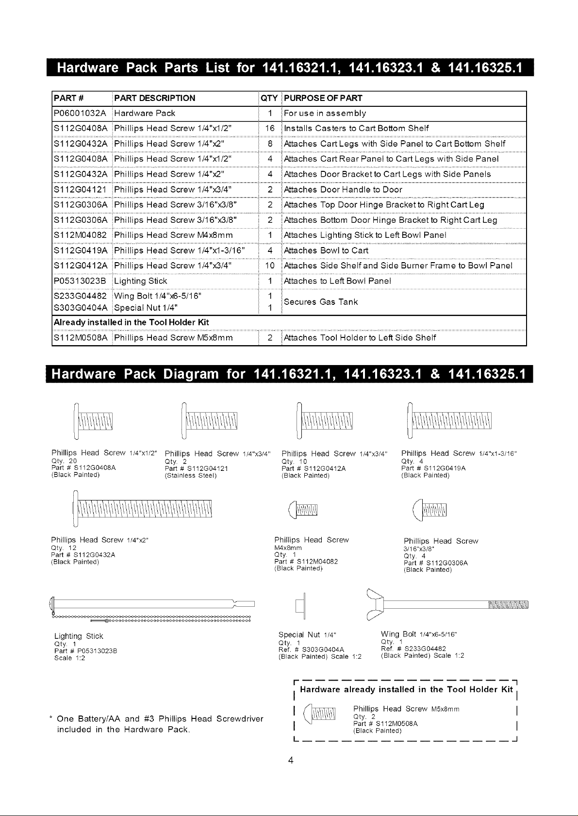
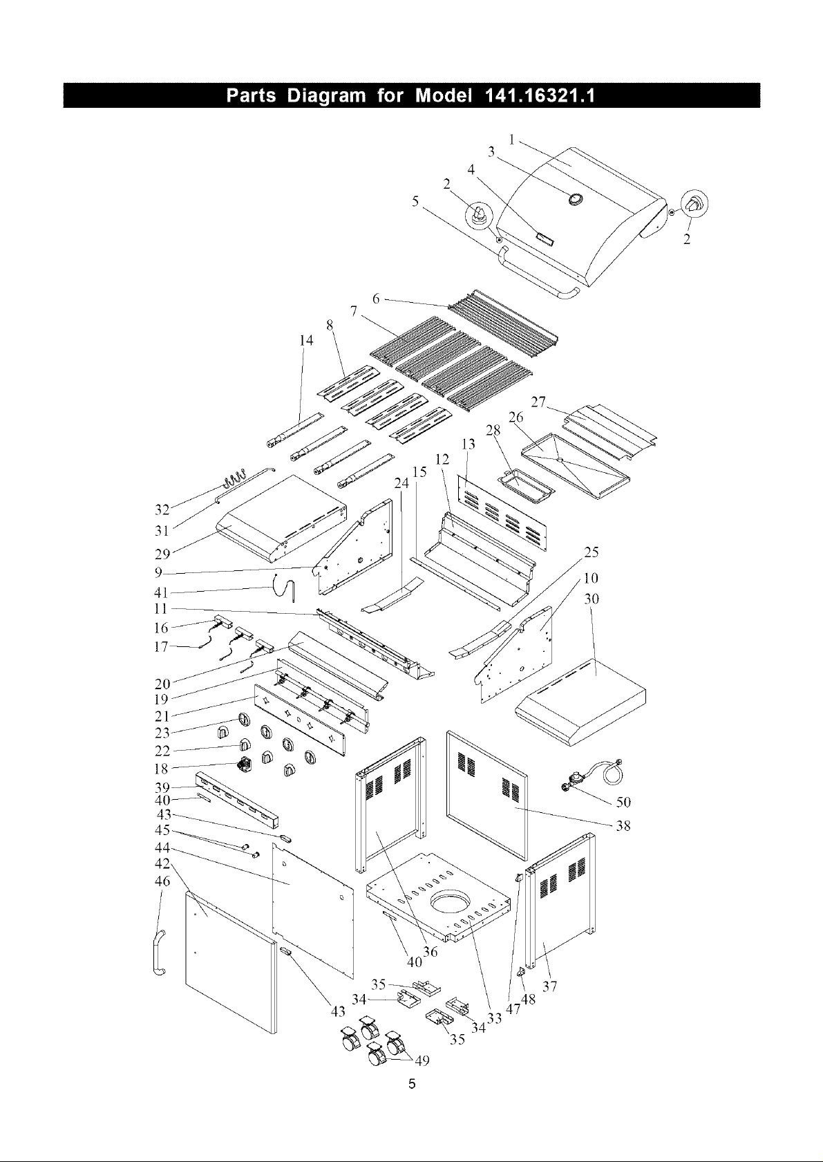
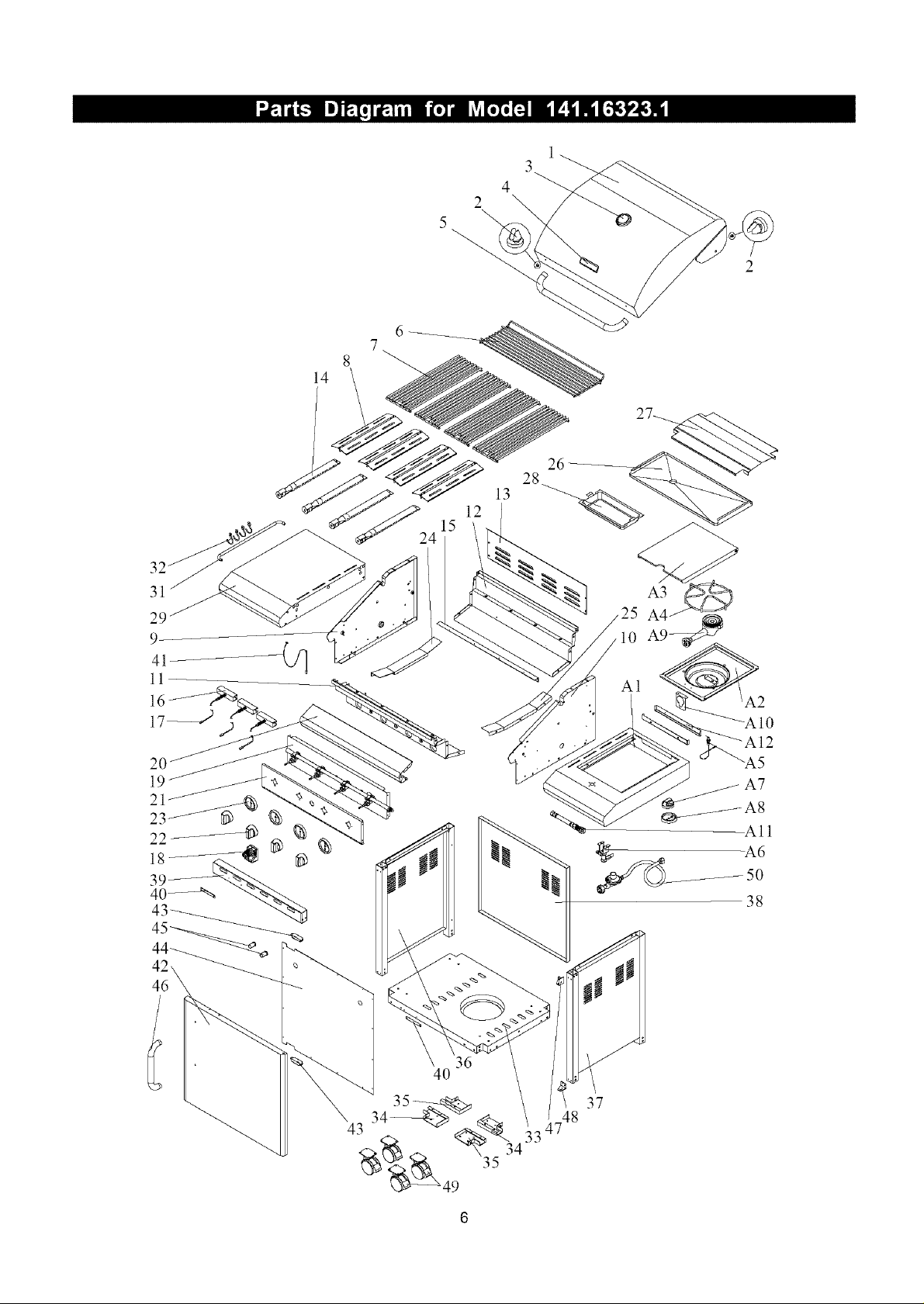
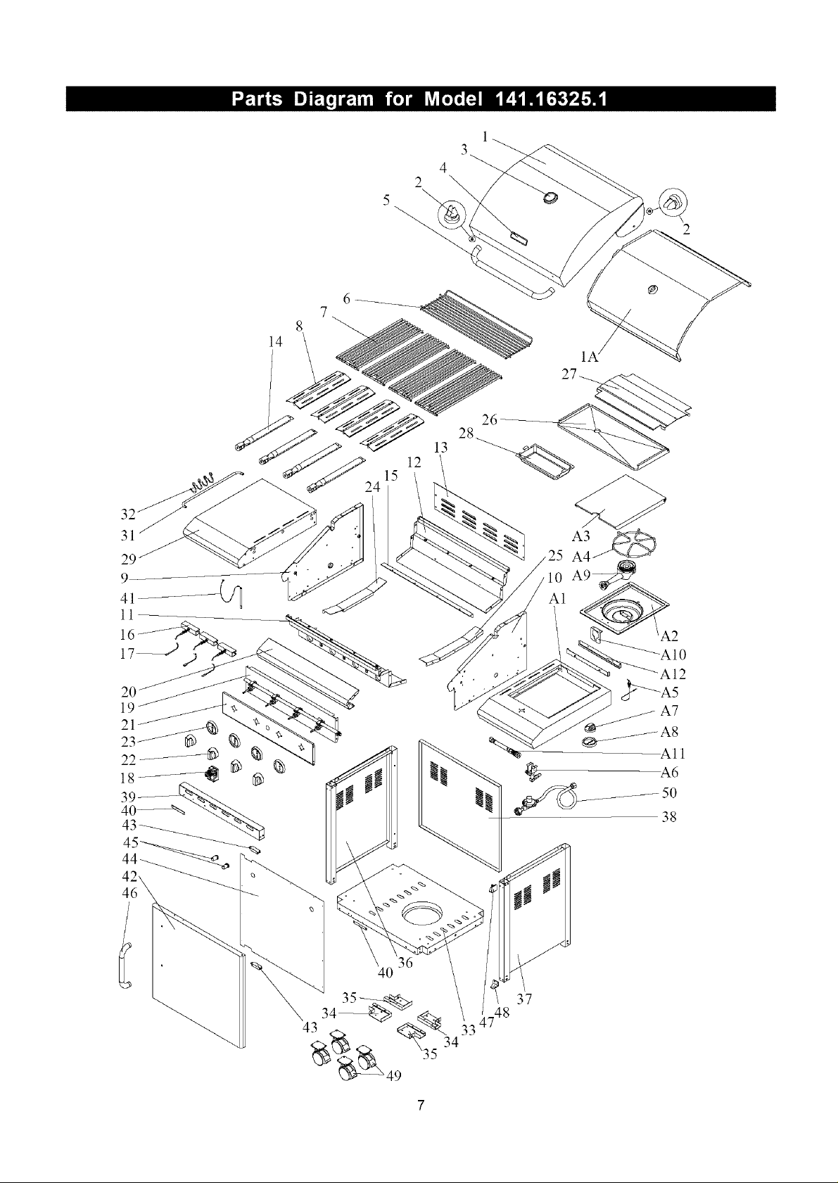
PART # PART DESCRIPTION CITY PURPOSE OF PART
P06001032A Hardware Pack 1 For use in assembly
$112G0408A iPhillips Head Screw 1/4"xl/2" 16 installs Casters to Cart Bottom Shelf
sl Phiiii sHead ..........................................................oCa Bo
.............................................. Panei................................................
sS_G043 ...........................................................ache aok t_e eia...............................................................
$112G0306A Phillips Head Screw 3/16"x3/8" 2 Attaches Bottom Door Hinge Bracket to Right Cart Leg
Si i2M04082 Phiiiips Head Screw _x8mm Attaches Lighting Stick to Le_Bowi Panei .................
Si i2G04i 2A Phii]ips Head Sciew i/4"_i4" i6 _taches Side She]i and Side Buiner Fiame io Bowi Panei
P05313023B Eighting stick ........................................... i Attaches to Left B0wl Panel .......................................................................................................
S303G0404A :Special Nut 1/4 1
Already installed in the Tool Holder Kit
Phillips Head Screw 1/4"xl/2" Phillips Head Screw 1/4"x3/4"
Qty. 20 Qty 2
Part # S112G0408A Part # $112G04121
(Slack Painted) (Stainless Steel)
Phillips Head Screw 1/4"x2" Phillips Head Screw Phillips Head Screw
Qty. 12 M4xSmm 3/16"x3/8"
Part # S112G0432A Qty 1 Qty. 4
(Black Painted) Part # $112M04082 Part # S112G0306A
,, _ecures L_as lanK
Head ............................................. .............................................................................................................................................................
Phillips Head Screw 1/4"x3/4"
Qty 1o
Part # S112G0412A
(Btack Painted)
(BIack Painted) (Black Painted)
Phillips Head Screw 1/4"xl-3/16"
Qty 4
Part # S112G0419A
(Stack Painted)
Lighting Stick Special Nut 1/4" Wing Bolt 1/4"x6-5/16"
Qty 1 Qty 1 Qty. 1
Part # P05313023B Ref. # S303G0404A Ref # $233G04482
Scale 1:2 (Btack Painted) ScaIe 1:2 (Black Painted) Scale 1:2
I-
Hardware already installed in the Tool Holder Kit
I
* One Battery/AA and #3 Phillips Head Screwdriver
included in the Hardware Pack.
I Phillips Head Screw M5x8mm
I Part # S112M0508A
L
Qty. 2
(Black Painted)
_/!/!/!/!/!/!/!/!/!/!/!/!/!/!1
1
I
I
I
J
31
29
4
2
5
6
7
8
14
27
25
II
43
10
30
5O
38
40
37
_748
35
31
1
3
4
2
26
28
13
12
15
24
16
17_
46
40
36
A1
A2
A7
37
48
-7
14
1
3
4
2
6
7
8
26
13
12
15
24
28
2_
11
19
21
22
43_
40
10 A9
A1
A2
5O
38
36
U48
37
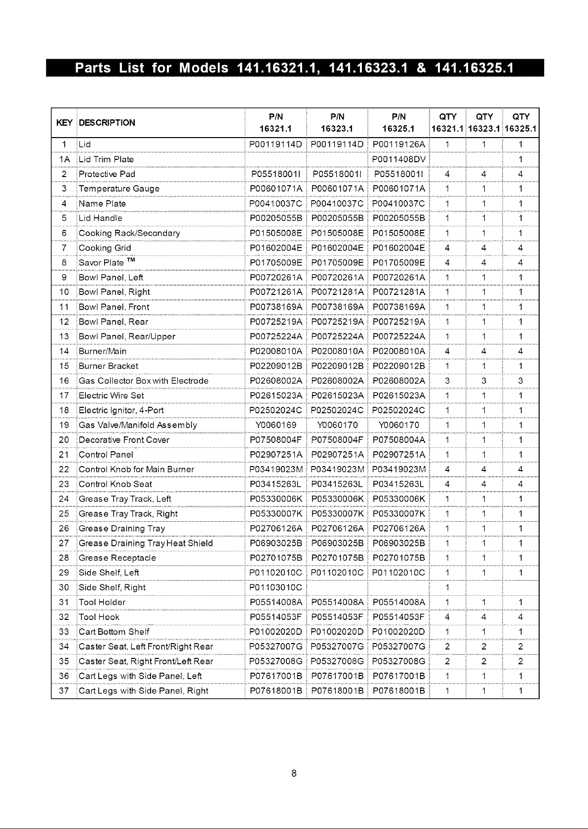
KEY DESCRIPTION
1 Lid P00119114D P00119114D P00119126A 1 1 1
2 Protective Pad P055180011 P055180011 P055180011 4 4 4
.......................................................Temperature Gauge i
4 Name Plate
5 Lid Handle PO0205055B P00205055B P00205055B 1 1 1
6 Cooking Rack/Secondary P01505008E P01505008E
7 Cooking Grid P01602004E P01602004E PO1602004E 4 4 4
8 Savor Plate TM P01705OO9E P01705009E P01705009E 4
PIN PIN PIN
16321.1 16323.1 16325.1
................. ..................................................................................................................................................................................................................i..........................................................i..........................................................i............................
............. .....................................................................................................................................................................................................i........................................................i.........................................................i............................
11 Bowl PaneI, Front POO738169A P00738169A P00738169A ...........................1....................................................i..........................................................i............................
12 Bowl Panel, Rear P00725219A P00725219A P00725219A 1 1 1
15 Burner Bracket P02209012B P02209012B P02209012B 1 1 1
20 Decorative FrontCover P07508004F P07508004F P07508004A 1 1 1
25 Grease TrayTrack, Right
27 Grease Draining TrayHeat Shield P06903025B P06903025B P06903025B 1 1 1
28 ....................................Grease Receptacle P0270i075B
29 Side Shelf, Left
30 Side Shelf, Right
3i Tool.................................Holder PS55i4668A 5655i4668A 565514668A
............. #
32 Tool Hook PO5514053F P05514053F P05514053F 4 4 4
35 Caster Seat, Right Front/Left Rear _P05327O08G PO5327008G P05327008G 2 2 2
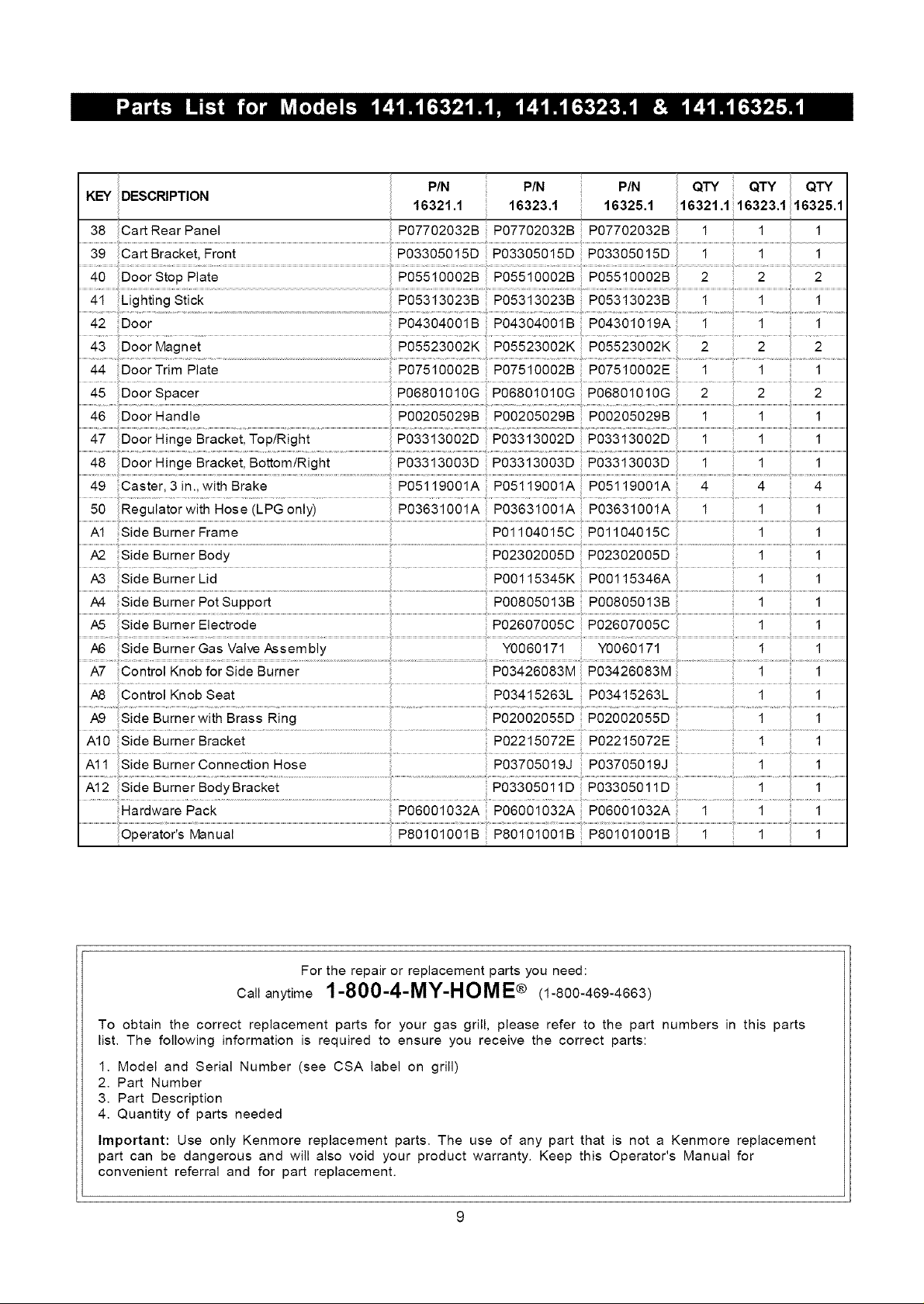
KEY DESCRIPTION PIN PIN
38 Cart Rear Panel
16321.1 16323.1 16325.1
P07702032B P07702032B P07702032Bii
PIN
44 DoorTrim Plate
49 Caster, 3 in., with Brake 4
A2 Side Burner Body P02302005D P02302005D
Side Bumer Lid .... P00ii5345K P00ii5346A
/_ Side BurnerPotSupport PO0805013B P00805013B
A7 Control Knob for Side Burner P03426083M
A10 Side Burner Bracket P02215072E P02215072E
P07510002B P07510002B P07510002E 1 1 ii 1
P03313002D P03313002D
ii P05119001A PO5119001A P05119001Ai
ii P06001032A P06001032A
PO6001032Aii 1Hardware Pack
4 _
For the repair or replacement parts you need:
Callanytime 1-800-4-MY-HOME® (1-800-469-4663)
To obtain the correct replacement parts for your gas grill, please refer to the part numbers in this parts
list. The following information is required to ensure you receive the correct parts:
1. Model and Serial Number (see CSA label on grill)
2. Part Number
3. Part Description
4. Quantity of parts needed
Important: Use only Kenmore replacement parts. The use of any part that is not a Kenmore replacement
part can be dangerous and will also void your product warranty. Keep this Operator's Manual for
convenient referral and for part replacement.
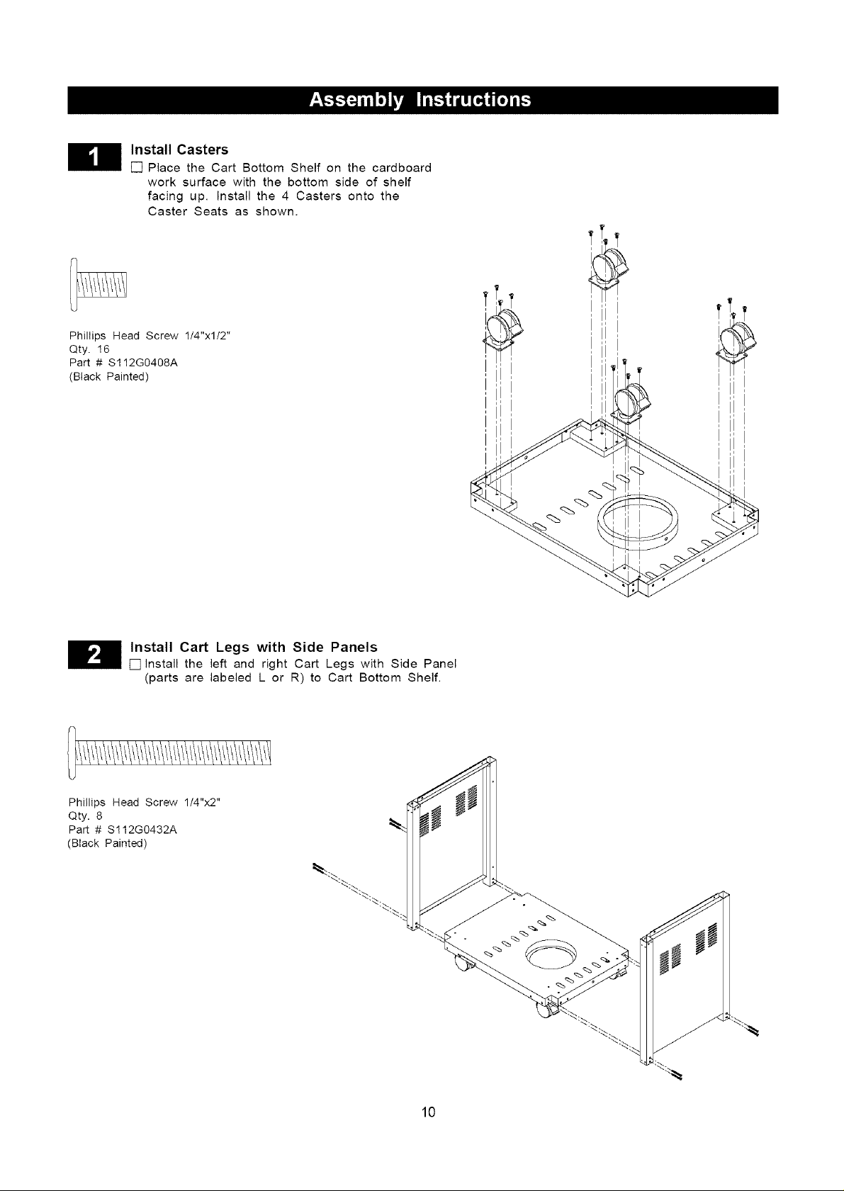
Install Casters
[] Place the Cart Bottom Shelf on the cardboard
work surface with the bottom side of shelf
facing up. Install the 4 Casters onto the
Caster Seats as shown.
Phillips Head Screw 1/4"xl/2"
Qty. 16
Part # S112G0408A
(Black Painted)
Install Cart Legs with Side Panels
[] Install the left and right Cart Legs with Side Panel
(parts are labeled L or R) to Cart Bottom Shelf.
Phillips Head Screw 1/4"x2"
Qty. 8
Part # S112G0432A
(Black Painted)
10
 Loading...