

Kenmore 141.16322 User Manual
Liquid Propane Gas (LPG) Gril
OPERATOR'S MANUAL
Model 141.16322 Model 141.16324
Grill Information Center
Call us first if you have any problem with this
product. We can hel p you with questions about
assembly and grill operation or if there are
damaged or missing parts when you unpack
this unit from the shipping box. Please call
before returning to the store.
1-888-317-7642
8am-8pm CST, Monday through Friday
IMPORTANT
. NOTETOASSEMBLER/INSTALLER:
Leave this manual with the consumer,
• NOTE TO CONSUMER:
Keep this manual forfuture reference.
* RECORDYOURSERIAL#
(see siIverCSA label on main body of grill)
• Failure to comply with these instructions could
result in afire orexplosion that could cause serious
bodily injury, death or property damage.
• Before using this gas appliance read all
instructions and perform all gas leak-check
procedures even if the product was pre-assembled
by the retaileror manufacturer.
• UseyourgrillatleastSfeetawayfromanywall
orsurface.UseyourgrillatleastSfeet away from
combustible objects that can melt or catch fire
(such as vinyl or wood siding, fences and over
hangs) or sources of ignition including pilot lights
on water heaters and live electrical appliances.
THIS GAS APPLIANCE
OUTDOOR USE ONLY.
Combustion byproducts produced when using this
product contain chemicals known to the State of
California to cause cancer, birth defects, or other
reproductive harm.
IS DESIGNED FOR
Manual # P80165001H - Date:2005/12/13
Table of Contents
Warranty
Primary Safety Warnings
Warranty Terms and Conditions
Pre-Assembly Instructions
Part Diagrams and Lists..............................
Assembly Instructions..................................
LP Gas Tank Installation.............................
Use & Care Instructions:
• Lighting Instructions
• Troubleshooting
Cleaning and Maintenance
Cooking Guide
Frequently Asked Questions.......................
............................................
............................
.................
..........................
..................................
........................................
.........................
..........
1-3
..............
..............
...........
4-9
......
10-16
......
17-19
............20
............21
......
22-23
.....
A1-A2
.....
A3-A4
2
3
IF YOU SMELL GAS:
1. Shut off gas to the appliance.
2 Extinguish any open flame.
3. Open lid.
4. If odor continues, keep away from
the appliance and immediately call
your gas supplier or your fire
department.
Leaking gas may cause a fire or
explosion which could result in property
damage, personal injury or death.
One-Year Full Warranty on Kenmore Grill
If this grill fails due to a defect in material or work
manship within one year from the date of purchase,
call 1-800-4-)VIY-HOIVIE®to arrange forfree repair(or
replacement if repair proves impossible).
Additional Limited Warranty on Specific Grill
Parts
From the date of purchase for the time
periods listed below, the following specific grill
parts will be supplied free of charge if they
fail to meet the conditions described. After the
first year from the date of purchase, you pay
for labor if you wish to have them installed.
• Lid Side Panels - Lifetime, no defects in material
or workmanship; 1 year, no paint loss.
• Stainless Steel Parts - 5 years (except Stainless
Steel Tube Burners - 10 years), no rust-through
• Porcelain coated parts - 3 years, no rust-through
• Cooking grids - 3 years, no rust-through
• Powder coated parts - 2 years, no rust-through
• Savor Plates - 2 years, no rust-through
All warranty coverage excludes ignitor batteries and
grill paint loss (except as specified above) or rusting
(except rust-through as specified above), which are
either expendable parts that can wear out from nor
mal use in less than a year, or are conditions that
can be the result of normal use, accident or improper
maintenance.
All warranty coverage is void if this grill is
ever used for commercial or rental purposes.
All warrranty coverage applies only if this grill
is used in the country where purchased.
1. Do not store spare LP cylinder
within 10 feet (3m) of this appliance.
2. Do not store or use gasoline or
other flammable liquids and
vapors within 25 feet (8m) of this
appliance.
3. When cooking with oil/grease, do
not allow the oil/grease to get
hotter than 350°F (117°C).
4. Do not leave oil/grease unattended.
Grill Installation Codes
The installation must conform with local codes or, in
the absence of local codes, with either the National
Fuel Gas Code, ANSI Z223.1/NFPA 54, or CAN/CGAB149.1, Natural Gas and Propane Installation Code.
This warranty gives you specific legal rights,
and you may have other rights which vary
from state to state.
Sears, Roebuck and Co., Dept. 817WA, Hoffman Estates, IL 60179 U.S.A.
© Sears, Roebuck and Co.
Pre-Assembly Instructions For Your Safety
A
Failure to comply with these instructions could
result in a fire or explosion that could cause
serious bodily injury, death or property damage.
Spiders and small insects can spin webs and
nest in the grill Burner Tubes during transit and
warehousing whici can -oac to a gas flow
obstruction resu t -c n i f s a."d around the
Burner Tubes. T-s :/pe of "F_-.SH3AC< FIRE"
can cause serious, grill,;damage' arc- c:=a:e an
unsafe coc-'ct-'g cc’cton for ;ho use.''
To reduce the chance of FLASHBACK =RE you
must clear the Burner Tubes as follows before
assemb.ing your grill. Also dc, loas: once
a month uri sU"’^’C' ano fall g/ s.jders
are active r yc. r area and if'you ■ c ' nas not
been usee fo' an extended perioc o^ tfne.
1. Remova :hc sc-'Oi'.' frc” ;ho roa-" of oacn Burner
using a Phillips ^eao Screwdriver
2. Carefully lift each Burner up and away from the
Gas Valve Orifice.
3. Check and clean Burner/Venturi Tubes for insects
and insect nests. A clogged tube can lead to a fire
beneath the grill.
4. Refer to the figure below and perform one of
these 3 cleaning methods:
□ METHOD 1: Bend a stiff wire or wire coat
hanger into a small hook as shown and run
the hook through the Burner Tube and inside
the Burner several times to remove debris.
TO CLEAN BURNER TUBE. ^
INSERT HOOK HERE
laDD DD QD DDD aD DD DDD DD DD DII DD DD II DDD DI ID DDD II DDl
T BurnerTube
n METHOD 2: Use a bottle brush with a flexible
handle and run the brush through the Burner
Tube and inside the Burner several times to
remove any debris.
□ METHOD 3: Use an air hose to force air
through each Burner Tube. The forced air
should pass debris or obstructions through
the Burner and out the Ports.
A
• LPG grill models must be used with Liquid
Propane Gas and the regulator assembly
supplied. Natural Gas models must be used
with Natural Gas only. Any attempt to convert the
grill from one fuel type to another is extremely
hazardous and will void the warranty.
• Never use your gas grill in a garage, porch, shed,
breezeway or any other enclosed area.
• Never obstruct the flow of ventilation air around
your gas grill housing.
• Never disconnect the gas regulator or any gas
fitting while your grill is lit. A lit grill can ignite
leaking gas and cause a fire or explosion which
could result in property damage, personal injury
or death.
• Keep gas regulator hose away from hot
grill surfaces and dripping grease. Avoid
unnecessary twisting of hose. Visually inspect
hose prior to each use for cuts, cracks,
excessive wear or other damage. If the hose
appears damaged do not use the gas grill. Call
Sears at 1-800-4-MY-HOME® (1-800-469-4663)
for a Kenmore replacement hose.
PRE-ASSEMBLY
Read and perform the following pre-assembly instruc
tions:
□ Tools Required for Assembly include:
• protective work gloves
• protective eyewear
• "L" Screwdriver (included in Hardware Pack
in parts box)
□ You will need assistance from another person to
handle the grill head and other large, heavy parts.
□ Open Lid of shipping carton and remove parts box
and packing materials. Lay cardboard sheet on floor
and use as a work surface to protect floor and grill
parts from scratches.
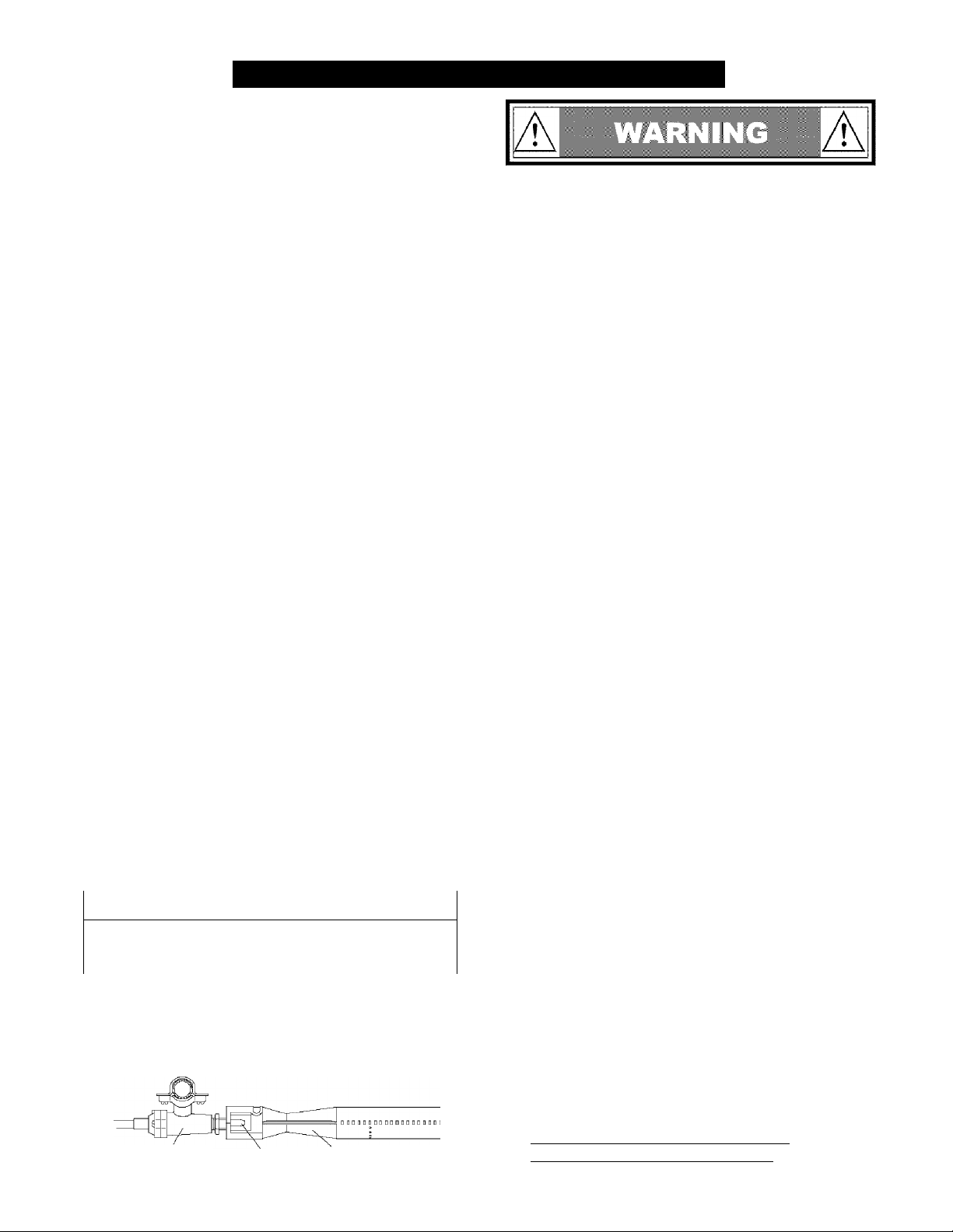
A
For safe operation ensure the Gas Valve Assem
bly Orifice is inside the Burner Tube before using
your grill. See figure. If the Orifice is not inside
the Burner Tube, lighting the Burner may cause
explosion and/or fire resulting in serious bodily
injury and/or property damage.
Gas Valve Assembly
Orifice
BurnerTube
A
□ Slice all four corners with a utility knife to lay open
the carton. This allows you to remove the grill head
and components packed inside.
□ Use the Hardware and Part Diagrams to ensure all
items are included and free of damage.
□ Do not assemble or operate the grill if it appears
damaged. If there are damaged or missing parts
when you unpack the shipping box or you have
questions during the assembly process, call the:
Grill Infoimation Center 1-888-317-7642
8am-8pm CST, Monday through Friday

Hardware Pack Parts List for 141.16322 & 141.16324
PART# PART DESCRIPTION QTY PURPOSEOFPART
P06001041B 'Hardware Pack for 141.16322 1 ¡For use in assembly
P06001040B 'Hardware Pack for 141.16324 ~ ¡For use in assembly
S135G04332
S132G04082
S135G04332
S211G06352 iWheel Bolt 3/8"x3-3/8" 2
S431G0610A SSpring Washer 3/8" 2 j Installs Wheels to Cart Legs
S372G0611A ¡Lock Nut 3/8" 2
P05515019F ;Wrench/No. 17 Customized ¡Tightens Casters and Wing Bolt Nuts
S132G04082 'Pattern Head Screw 1/4"x1/2" 4 ¡Attaches Cart Rear Panel to Cart(For Model 141.16324)
S132G04082 iPattern Head Screw 1/4"x1/2" "a
S135G04332
S132G04082
S132G04082 'Pattern Head Screw 1/4"x1/2" 4
P05318022B ¡Door Stop/Magnet 2
S132G04121 ¡Pattern Head Screw 1/4"x3/4" 4 ¡Attaches Door Handles to Doors
S225G0406A Door Bolt 1/4"x3/8" 2 "Attaches Doors to Cart
S135G04101
P05313023B 'Lighting Stick 1 ¡Attaches to Left Bowl Support Bracket
S132M04082 ¡Pattern Head Screw M4>fimm 1 "Attaches Lighting Stick to Left Bowl Support Bracket
S132G04122 ¡Pattern Head Screw 1/4"x3/4" 10 ¡Attaches Side Shelf and Side Burner Frame to Grill Head
S132M04082 • Pattern Head Screw M4>6mm 2
S411M04122 ¡Plain Washer M4 2
P05515020B i”L" Screwdriver 1 "Tightens all the Pattern Head Screws
S233G0453A ¡Wing Bolt 1/4"x5-1/8”
S303G0404A 'Special Nut 1/4" 1
P03426083H ¡Control Knob for Side Burner 1 " Attaches to Side Burner Frame
P05523003G ¡Door Stop Plate 1 'Attaches to Magnet
'Pattern Head Screw, Part Threaded
h/4"x2-3/4"
1 Pattern Head Screw 1/4"x1/2"
jPattern Head Screw, Part Threaded
H/4"x2-3/4"
' Pattern Head Screw, Part Threaded
:1/4"x2-3/4"
iPattern Head Screw 1/4"x1/2" 2 'Attaches Door Bracket to Cart
'Pattern Head Screw, Part Threaded
h/4"x5/8"
4
'Attaches Cart Legs to Bowl Support Bracket
4
8 ¡Attaches Cart Legs to Cart Bottom Shelf
...
"Attaches Cart Side Panels to Cart
2 ' Attaches Door Bracket to Cart
¡Attaches Magnetic Door Stops to Cart
2 (Attaches Doors to Door Bracket
"Attaches to Side Burner Gas Valve Bracket
1
(Secures Gas Tank
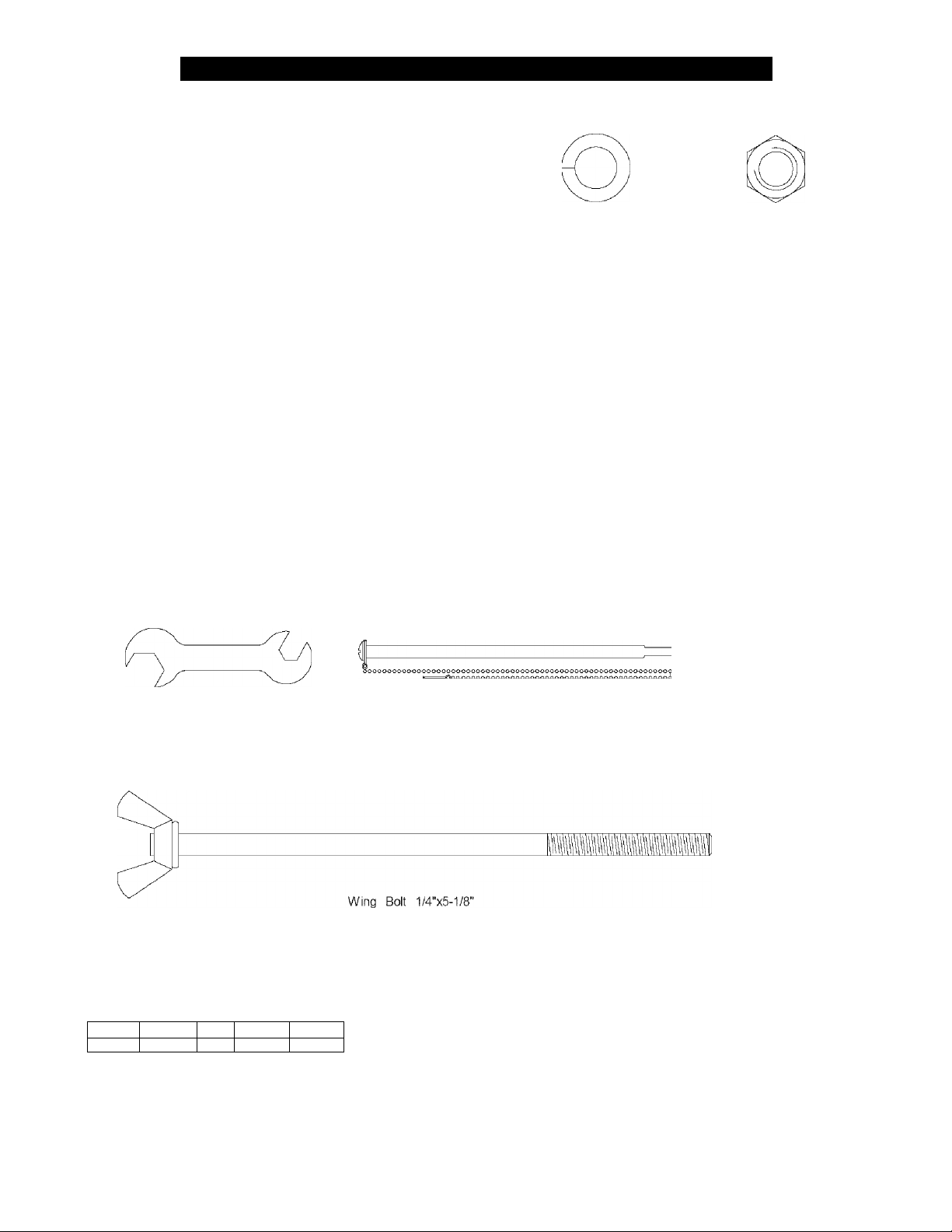
Hardware Pack Diagram for 141.16322 & 141.16324
Wheel Bolt 3/8''x3-3/8"
Qty. 2
Part # S211G06352
Pattern Head Screw, Part Threaded
1/4"x2-3/4"
Qty. 14
Part # S135G04332
Pattern Head Screw IVI4x8mm
Qty. 3
Part # S132M04082
Plain Washer M4
Qty. 2
Part # S411M04122
Pattern Head Screw 1/4"x3/4"
Qty. 10
Part. # S132G04122
Door Bolt 1/4"x3/8"
Qty. 2
Part # S225G0406A
Pattern Head Screw
Part Threaded 1/4"xi
Qty. 2
Part # S135G04101
Spring Washer 3/8”
Qty. 2
Part # S431G0610A
Pattern Head Screw 1/4"x3/4"
Qty. 4
Part # S132G04121
Lock Nut 3/8"
Qty. 2
Part # S372G0611A
“L” Screwdriver
Qty. 1
Part # P05515020B
Scale 1:2
Wrench/No.17 Customized
Qty. 1
Part # P05515019F
Scale 1:2
Qty. 1
Part # S233G0453A
Scale 1:2
1 [ 1 (
rr
Door Stop/Magnet
Qty. 2
Part # P05318022B
Scale 1:2
One Battery/AA included in the Hardware Pack.
Lighting Stick
Qty. 1
Part # P05313023B
Scale 1:2
Door Stop Plate
Qty. 1
Part # P05523003G
Scale 1:2
Pattern Head Screw 1/4"x1/2"
Qty. 22 (Model 141.16324)
Qty. 18 (Model 141.16322)
Part # S132G04082
Special Nut 1/4”
Qty. 1
Part # S303G0404A
Control Knob for Side Burner
Qty. 1
Part # P03426083H
Scale 1:2
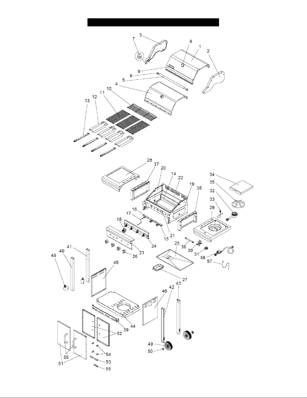
Parts Diagram for Model 141.16322
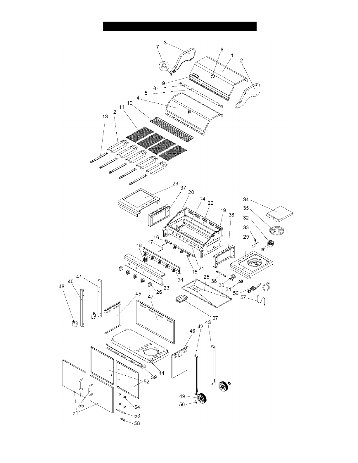
Parts Diagram for Model 141.16324

Parts List for Models 141.16322 & 141.16324
KEY DESCRIPTION
1 iLid Plate j P0014604EA P0014702EA 1 1
2 !Lid Side Panel, Right j P0010607DJ P0010607DJ 1 1
3 !Lid Side Panel, Left i P0010506DJ P0010506DJ 1 1
4 iLid Trim Plate i P0011414QJ P0011413QJ 1 1
5 Lid Handle ■ P00205072B P00205071B 1 1
6 ;Lid Handle Heat-Insulating Spacer i P06801001A P06801001A 2 2
7 Protective Pad i P055180031 ' P05518003i"
8 :Temperature Gauge i P00601174A P00601174A 1 1
9 Name Plate i P00410037C P00410037C 1 1
10 Cooking Rack/Secondary [ P01504001E P01506001E 1 1
11 iCooking Grid i P01602008F P01602008F 3 -
12 i Savor Plate® i P01705019F P01705019F 4 5
13 ;Burner/Main i P02008018A P02008018A 4 5
14 i Burner Bracket i P02213003B P02213043B 1 1
15 Gas Collector Box ■ P02626001A P02626001A 2 3
16 IGas Collector Boxwith Electrode i P02608005A P02608005A " 1 1
17 ^Electric Wire Set i P02615084A P02615085A 1 1
18 ;Electric Ignitor, 2-Port i P02502172C P02502172C 1
19 Bowl Panel, Right P00721324A P00721324A 1 1
20 iBowl Panel, Left ; ' P00720304A ' P00720304A 1 1
21 ;Bowl Panel, Front ■ P0073826GA P0073825GA 1 1
22 IBowl Panel, Rear ■ P0072547GA P0072546GA 1 1
23 Control Panel ; P02906037B P02908117B 1 1
24 Gas Valve/Manifold Assembly Y0060296 Y0060289 1 1
25 iGrease Draining Tray i P02717147B P02717137B 1 1
26 ■Control Knob i P03419083N P03419083N 4 5
27 ■Grease Receptacle i P02701087B P02701087B 1 1
28 iSide Shelf, Left ■i PO1102040C P01102040C 1 1
29 ■ Side Burner Frame P01104039C P01104039C i 1
30 ■ Gas Valve for Side Burner Y0060290 Y0060290 ' 1 1
31 ■ Control Knob for Side Burner i P03426083H P03426083H 1 1
32 Side Burner with Brass Ring ■ P02002055D P02002055D 1 1
33 ■ Side Burner Electrode i P02607007A P02607007A 1 1
34 ■ Side Burner Lid i P0011503EA ' P0011503EA ' 1 1
35 ■ Side Burner Pot Support ■ P00805013B P00805013B 1 1
3f ■Side Burner Connection Tube : P03705002A P03705002A 1 1
37 ■ Bowl Support Bracket, Left ■ P01304006D P01304006D 1 1
38 ■ Bowl Support Bracket, Right ■ P01305010D P01305010D 1 1
P/N
16322
P/N
16324
QTY
16322
. . . .
QTY
16324
2
Parts List for Models 141.16322 & 141.16324
KEY DESCRIPTION
39 Door Bracket { P03305025D P03305024D : 1 1
40 iCart Leg, Left-Front Caster Side i P00910008C P00910008C I 1 1
41 iCart Leg, Left-Back Caster Side ! P00911008C P00911010C i 1 1
42 Cart Leg, Right-Front Wheel Side i P00912008C P00912008C ! 1
43 Cart Leg, Right-Back Wheel Side s P00913010C P00913012C : 1 ■
' 44 " jCart Bottom Shelf ( P01002023D
45 i Cart Side Panel, Left ( P07605007B P07605007B : 1 1
46 iCartSide Panel, Right :! P07606007B P07606007B i 1 1
47 iCart Rear Panel P07702046B : 1
48 iCaster, 3 in., with Brake ; P05106004A P05106004A ! 2 2
49 ::Wheel ! P05101001À PÒ5101001A ; "2 ' 2
50 ¡Wheel Hub Cap i P05122001A P05122001A : 2 2
51 (Door i P04301025A P04301024A ! 2 2
52 iDoor Trim Plate i P07510012B P07510011B i 2 2
......
53" " I Door Magnet i P05318022B P05318022B !
54 iDoor Spacer i P06801016G P06801016G : 4 4
55 ¡Door Handle i P00203009B P00203009B ! 2 2
56 i Regulator with Hose (LPG) i P03633008A P03601008A = 1 1
57 ' i Lighting Stick : P05313023B P05313023B ' ; 1 1
58 ¡Door Stop Plate ; P05523003G P05523003G I 1 1
Hardware Pack I P06001041B P06001040B ; 1 1
Operator's Manual
1 P86Ì650ÒÌH
P/N
16322
..........
P/N I
16324
P01004015D s ' 1 1
P80165001H 1 i ' 1
QTY
16322
■ 2
QTY
16324
2
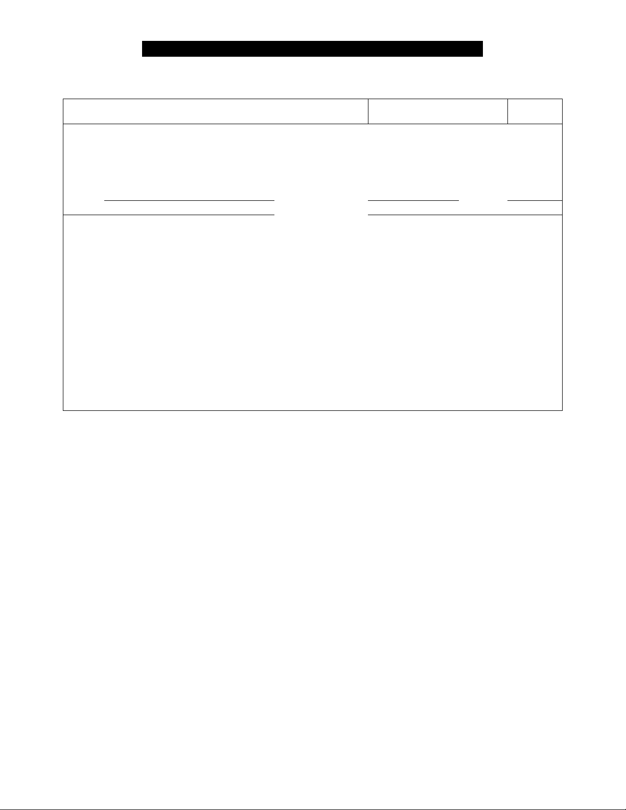
For the repair or replacement parts you need:
Call anytime 1-800-4-MY-HOME®
To obtain the correct replacement parts for your gas grill, please refer to the part numbers in this parts
list. The following information is required to ensure you receive the correct parts:
1. Model and Serial Number (see CSA label on grill)
2. Part Number
3. Part Description
4. Quantity of parts needed
Important: Use only Kenmore replacement parts. The use of any part that is not a Kenmore replacement
part can be dangerous and will also void your product warranty. Keep this Operator's Manual for
convenient referral and for part replacement.
(i-8oo-
469-4663
)
 Loading...