

Kenmore 141.16306 Owner's Manual

Use and Care Guide
LiquidPropaneGas(LPG)Grill
• Safety
• Assembly
• Use and Care
• Cooking Guide
• Frequently Asked Questions
Model 141.16306
Call us first if you have any problem with
this product. We can help you with ques-
tions about assembly and grill operation or
if there are damaged or missing parts
when you unpack this unit from the ship-
ping box. Please call before contacting
your local retailer.
1-888-317-7642
8am-8pm CST, Monday throuqh Friday
• NOTE TO ASSEMBLER/INSTALLER:
Leave this manual with the consumer.
• NOTETO CONSUMER:
Keep this manual for future reference.
• RECORDYOURSERIAL#
(see silver CSA label on main body of grill)
• Failure to comply with these instructions could
result in a fire or explosion that could cause
serious bodily injury, death or propertydamage.
• Whether this grill was assembled by you or
someone else, you must read this entire manual
before using your grill to ensure the grill is
properly assembled, installed and maintained.
• Use your grill at least 3 feet away from any
wall or surface. Use your grill at least 3 feet
away from combustible objects that can melt or
catch fire such as vinyl or wood siding, fences
and overhangs or sources of ignition including
pilot lights on water heaters and live electrical
appliances.
• THIS GASAPPLIANCE ISDESIGNED FOROUT-
DOOR USE ONLY.
• Never use your gas grill in a garage, porch,
shed, breezeway or any other enclosed area.
• Never obstruct the flow of ventilation air
around your gas grill housing.
• Never disconnect the gas regulator or any gas
fitting while your grill is lit. A lit grill can ignite
leaking gas and cause a fire or explosion which
could result inproperty damage, personal injury
or death.
Sears, Roebuck and Co., Hoffman Estates, IL 60179, USA www.sears.com
Manual # P80104001P - Date:2007/09/12

Primary Safety Warnings ........................... 1-3
Warranty Terms and Conditions .................. 2
Pre-Assembly Instructions .............................. 3
Part Diagrams and Lists .......................... 4-8
Assembly Instructions ............................... 8-15
LP Gas Tank Installation ...................... 16-18
Use & Care Instructions:
• Lighting Instructions ................................. 19
• Troubleshooting .......................................... 20
Cleaning and Maintenance ..................... 21-22
Cooking Guide ........................................ A1-A5
Frequently Asked Questions ................ A6-A7
Repair Protection Agreement ..................... A8
Kenmore Full Warranty
If this grill fails due to a defect in material or work-
manship within one year from the date of purchase,
call 1-800-4-MY-HOME® to arrange for free repair
(or replacement if repair proves impossible).
Limited Warranty on Selected Grill Parts
From the date of purchase for the time periods listed
below, the following specific grill parts will be replaced
free of charge if they rust through. After the first year
from the date of purchase you must pay the labor
cost if you wish to have them installed.
• Stainless Steel Parts (including Burners) 10
Years
• Painted Steel Parts 3 Years
• Cooking Grids 2Years
• Heat Diffusers 2Years
All warranty coverage excludes ignitor batteries and
grill part paint loss (except as specified above) or rust-
ing (except for rust-through a specified above), which
are either expendable parts that can wear out from
normal use in less than a year, orare conditions that
can be the result of normal use, accident or improper
maintenance.
IF YOU SMELL GAS:
1. Shut off gas to the appliance.
2 Extinguish any open flame.
3. Open lid.
4. If odor continues, keep away from
the appliance and immediately call
your gas supplier or your fire
department.
.
Do not store or use gasoline or
other flammable liquids or vapors
in the vicinity of this or any other
appliance.
.
An LP cylinder not connected for
use shall not be stored in the
vicinity of this or any other
appliance.
Combustion byproducts produced when using
this product contain chemicals known to the
State of California to cause cancer, birth
defects, or other reproductive harm.
Brass components on the grill, such as
hose fittings, propane cylinder valves (sold
separately) and burner valve stems, contain
lead which is known to the State of Califor-
nia to cause cancer, birth defects, or other
reproductive harm.
All warranty coverage is void if this grill is ever used
for commercial or rental purposes.
All warranty coverage applies only if this grill is
used in the United States.
This warranty gives you specific legal rights, and
you may have other rights which vary from state to
state.
Sears, Roebuck and Co., Hoffman Estates, IL
Grill Installation Codes
The installation must conform with local codes or, in
the absence of local codes, with either the National
Fuel Gas Code, ANSI Z223.1/NFPA 54, Natural Gas
and Propance installation Code, CSA B149.1, or
Propane Storage and Handling Code, B149.2.
LPG grill models must be used with Liquid
Propane Gas and the regulator assembly
supplied. Natural Gas models must be used
with Natural Gas only. Any attempt to convert
the grill from one fuel type to another is
extremely hazardous and will void the war-
ranty.
Keep gas regulator hose away from hot grill
surfaces and dripping grease. Avoid unneces-
sary twisting of hose. Visually inspect hose
prior to each use for cuts, cracks, excessive
wear or other damage. If the hose appears
damaged do not use the gas grill. Call 1-800-
770-9769 for a authorized replacement hose.
© Sears Brands, LLC
2
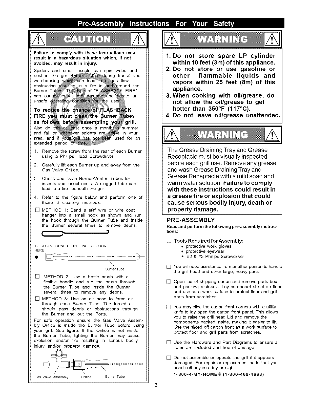
Failure to comply with these instructions may
result in a hazardous situation which, if not
avoided, may result in injury.
Spiders and small insects can spin webs and
nest in the grill ing transit and
warehousing flow
obstruction the
Burner Tu FIRE"
can cau,, an
unsafe
To ;K
FIRE bes
as folk grill.
Also do _ummer
and fall or in your
area, and if used for an
extended period
1. Remove the screw from the rear of each Burner
using a Phillips Head Screwdriver.
2. Carefully lift each Burner up and away from the
Gas Valve Orifice.
3. Check and clean BurnerNenturi Tubes for
insects and insect nests. A clogged tube can
lead to a fire beneath the grill.
4. Refer to the figure below and perform one of
these 3 cleaning methods:
[] METHOD 1: Bend a stiff wire or wire coat
hanger into a small hook as shown and run
the hook through the Burner Tube and inside
the Burner several times to remove debris.
1. Do not store spare LP cylinder
within 10 feet (3m) of this appliance.
2. Do not store or use gasoline or
other flammable liquids and
vapors within 25 feet (8m) of this
appliance.
3. When cooking with oil/grease, do
not allow the oil/grease to get
hotter than 350°F (117°C).
4. Do not leave oil/grease unattended.
The Grease Draining Tray and Grease
Receptacle must be visually inspected
before each grill use. Remove any grease
and wash Grease Draining Tray and
Grease Receptacle with a mild soap and
warm water solution. Failure to comply
with these instructions could result in
a grease fire or explosion that could
cause serious bodily injury, death or
property damage.
PRE-ASSEMBLY
Read and perform the following pre-assembly instruc-
tions:
TO CLEAN BURNER TUBE, INSERT HOOK
HERE
\
BumerTube
[] METHOD 2: Use a bottle brush with a
flexible handle and run the brush through
the Burner Tube and inside the Burner
several times to remove any debris.
[] METHOD 3: Use an air hose to force air
through each Burner Tube. The forced air
should pass debris or obstructions through
the Burner and out the Ports.
For safe operation ensure the Gas Valve Assem-
bly Orifice is inside the Burner Tube before using
your grill. See figure. If the Orifice is not inside
the Burner Tube, lighting the Burner may cause
explosion and/or fire resulting in serious bodily
injury and/or property damage.
/
Gas Valve Assembty Orifice BurnerTube
[] Tools Required forAssembly:
• protective work gloves
• protective eyewear
• #2 & #3 Phillips Screwdriver
[]
You will need assistance from another person to handle
the grill head and other large, heavy parts.
[]
Open Lid of shipping carton and remove parts box
and packing materials. Lay cardboard sheet on floor
and use as a work surface to protect floor and grill
parts from scratches.
[] You may slice the carton front corners with a utility
knife to lay open the carton front panel. This allows
you to raise the grill head Lid and remove the
components packed inside, making it easier to lift.
Use the sliced off carton front as a work surface to
protect floor and grill parts from scratches.
[] Use the Hardware and Part Diagrams to ensure all
items are included and free of damage.
[] Do not assemble or operate the grill if it appears
damaged. For repair or replacement parts that you
need call anytime day or night:
1-800-4-MY-HOME® (1-800-469-4663)
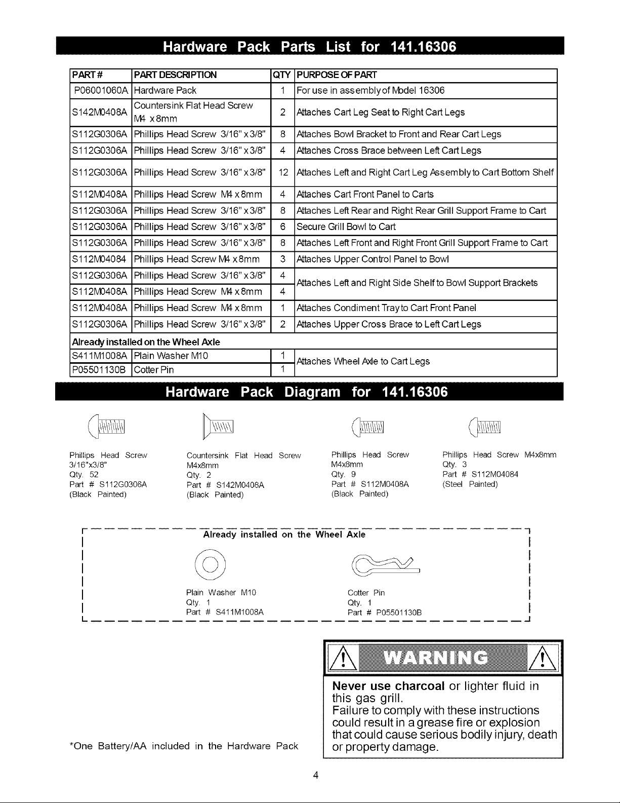
PART#
P06001060A
S142M0408A
S112G0306A
S112G0306A
PARTDESCRIPTION
Hardware Pack
Countersink Flat Head Screw
M4 x8mm
Phillips Head Screw 3/16" x3/8"
Phillips Head Screw 3/16" x3/8"
QTY PURPOSE OF PART
1 Forusein assemblyofMode116306
2 AttachesCart Leg Seat to Right Cart Legs
8 AttachesBowl Bracket toFrontand Rear CartLegs
4 AttachesCross Brace between LeftCart Legs
S112G0306A
S112M0408A
S112G0306A
S112G0306A
S112G0306A
$112M04084
S112G0306A
S112M0408A Phillips HeadScrew M4x8mm
S112M0408A Phillips HeadScrew M4x8mm
S112G0306A Phillips Head Screw 3/16"x3/8"
Phillips Head Screw 3/16" x3/8"
Phillips Head Screw M4x8mm
Phillips Head Screw 3/16" x3/8"
Phillips Head Screw 3/16" x3/8"
Phillips Head Screw 3/16" x3/8"
Phillips Head Screw M4x8mm
Phillips Head Screw 3/16" x3/8"
12 AttachesLeft and RightCart Leg Assemblyto Cart Bottom Shelf
4 AttachesCart FrontPanel toCarts
8 AttachesLeft Rearand Right RearGrill Support Frame to Cart
6 Secure Grill Bowl to Cart
8 AttachesLeft Frontand RightFront Grill Support Frameto Cart
3 AttachesUpper Control Panel toBowl
4
Attaches Left and RightSide Shelfto Bowl Support Brackets
4
1 AttachesCondimentTrayto Cart FrontPanel
2 AttachesUpper Cross Brace to Left Cart Legs
Alreadyinstalled ontheWheel Axle
$411M1008A Plain Washer M10
P05501130B Cotter Pin
Phillips Head Screw Countersink Flat Head Screw Phillips Head Screw Phillips Head Screw M4x8mm
3/16"x3/8" M4x8mm M4xSmm Qty. 3
Qty. 52 Qty. 2 Qty. 9 Part # $112M04084
Part # Sl!2G0306A Part # S142M0408A Part # S112M0408A (Steel Painted)
(Black Painted) (Black Painted) (Black Painted)
Attaches Wheel Axle to Cart Legs
Already installed on the Wheel Axle
Plain Washer MI0
Qty. 1
Part # S411M1008A
*One Battery/AA included in the Hardware Pack
3
Cotter Pin
Qty. 1
Part # P05501130B
Never use charcoal or lighter fluid in
this gas grill.
Failure to comply with these instructions
could result in a grease fire or explosion
that could cause serious bodily injury, death
or property damage.

1
6
17
56
37
38
23
28
24
32
33
35
48

KEY DESCRIPTION PART # QTY
1 Lid P00145059B 1
2 Lid Hinge Support, Left P00127314B 1
3 Lid Hinge Support, Right P00128314B 1
4 Temperature Gauge P00601287C 1
5 Temperature Gauge Seat P00614017E 1
6 Name Plate P00410041C 1
7 Protective Pad, Rear P055180011 2
8 Protective Pad, Front P055180041 2
9 Lid Handle P02205096M 1
10 Lid Handle Heat Insulating Spacer P06901025A 2
11 Lid Handle Bracket P03303106A 2
12 Cooking Rack/Secondary P01508027E 1
13 Cooking Grid P01615031E 6
14 Heat Diffuser P01717005E 6
15 Grill Bowl P0071337GA 1
16 Bowl Panel, Upper P06905055A 1
17 Burner P02008060A 6
18 Burner Bracket P02206111B 1
19 Gas Collector Boxwith Electrode, 12" P02601001M 2
20 Gas Collector Boxwith Electrode, 18" P02601002M 1
21 Gas Collector Boxwith Electrode, 24" P02601003M 1
22 Gas Collector Boxwith Electrode, 30" P02601004M 1
23 Gas Collector Boxwith Electrode, 35" P02601005M 1
24 Electric Ignitor, 6-Port P02502265C 1
25 Control Panel, Upper P0291097ES 1
26 Control Panel P0291099FA 1
27 Regulator with Hose P03631001A 1
28 Gas Valve/Manifold Assembly Y0060491 1
29 Gas Valve/Manifold Assembly Bracket P03327045D 2
30 Lighting Stick Assembly P05313010B 1
31 Control Knob P03419483H 6
32 Control Knob Seat P034150731 6
33 Grease Draining Tray P02708277B 1
34 Grease Receptacle P02701087B 1
35 Grill Support Frame, Left Front/Right Rear P01316009D 2
36 Grill Support Frame, Right Front/Left Rear P01316010D 2
37 Side Shelf, Left P01102052D 1
38 Decorative Panel for Side Shelf, Left P07503008P 1
39 Side Shelf, Right P01103041D 1
40 Decorative Panel for Side Shelf, Right P07502021P 1
41 Cart Leg, Left Front/Right Rear P00907009C 2
42 Cart Leg, Right Front/Left Rear P00907010C 2
43 Bowl Support Bracket P01306023D 2
44 Cart Bottom Shelf P01005050D 1
45 Cart Panel, Front P05705001C 1
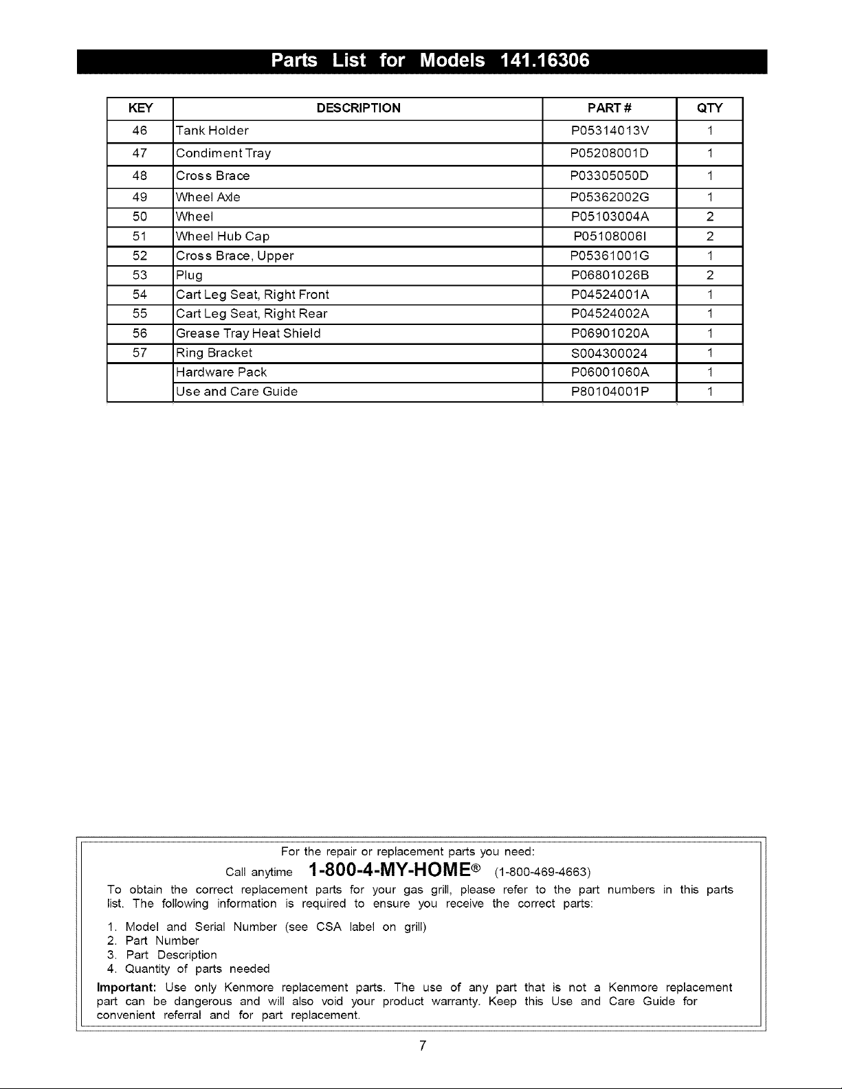
KEY DESCRIPTION PART # QTY
46 Tank Holder P05314013V 1
47 Condiment Tray P05208001D 1
48 Cross Brace P03305050D 1
49 Wheel Axle P05362002G 1
50 Wheel P05103004A 2
51 Wheel Hub Cap P051080061 2
52 Cross Brace, Upper P05361001G 1
53 Plug P06801026B 2
54 Cart Leg Seat, Right Front P04524001A 1
55 Cart Leg Seat, Right Rear P04524002A 1
56 Grease Tray Heat Shield P06901020A 1
57 Ring Bracket S004300024 1
Hardware Pack P06001060A 1
Use and Care Guide P80104001P 1
For the repair or replacement parts you need:
Ca,anytime1-800-4-MY-HOME® (1-800-469-4663)
To obtain the correct replacement parts for your gas grill, please refer to the part numbers in this parts
list. The following information is required to ensure you receive the correct parts:
1. Model and Serial Number (see CSA label on grill)
2. Part Number
3. Part Description
4. Quantity of parts needed
Important: Use only Kenmore replacement parts. The use of any part that is not a Kenmore replacement
part can be dangerous and will also void your product warranty. Keep this Use and Care Guide for
convenient referral and for part replacement.
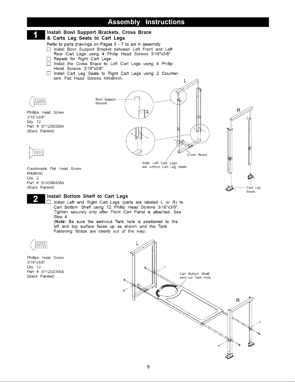
Install Bowl Support Brackets, Cross Brace
& Carts Leg Seats to Cart Legs
Refer to parts drawings on Pages 5 - 7 to aid in assembly
[] install Bowl Support Bracket between Left Front and Left
Rear Cart Legs using 4 Phillip Head Screws 3/16"x3/8".
[] Repeat for Right Cart Legs.
[] install the Cross Brace to Left Cart Legs using 4 Phillip
Head Screws 3/16"x3/8".
[] install Cart Leg Seats to Right Cart Legs using 2 Counter-
sink Flat Head Screws M4x8mm.
Phillips Head Screw
3/16"x3/8"
Qty. 12
Part # S112G0306A
(Black Painted)
Countersink Flat Head Screw
M4x8mm
Qty. 2
Part # S142M0408A
(Black Painted)
Install Bottom Shelf to Cart Legs
[] install Left and Right Cart Legs (parts are labeled L or R) to
Cart Bottom Shelf using 12 Phillip Head Screws 3/16"x3/8".
Tighten securely only after Front Cart Panel is attached. See
Step 4.
(Note: Be sure the semi-cut Tank hole is positioned to the
left and top surface faces up as shown and the Tank
Fastening Straps are clearly out of the way).
Bowl Support
Bracket
Note: Left Cart Legs
are without Cart Leg Seats
Cross Brace
i
i
i
Cart Leg
Seats
Phillips Head Screw
3/16"x3/8"
Qty. 12
Part # S112G0306A
(Black Painted)
Cart Bottom Shelf
semi-cut Tank Hole
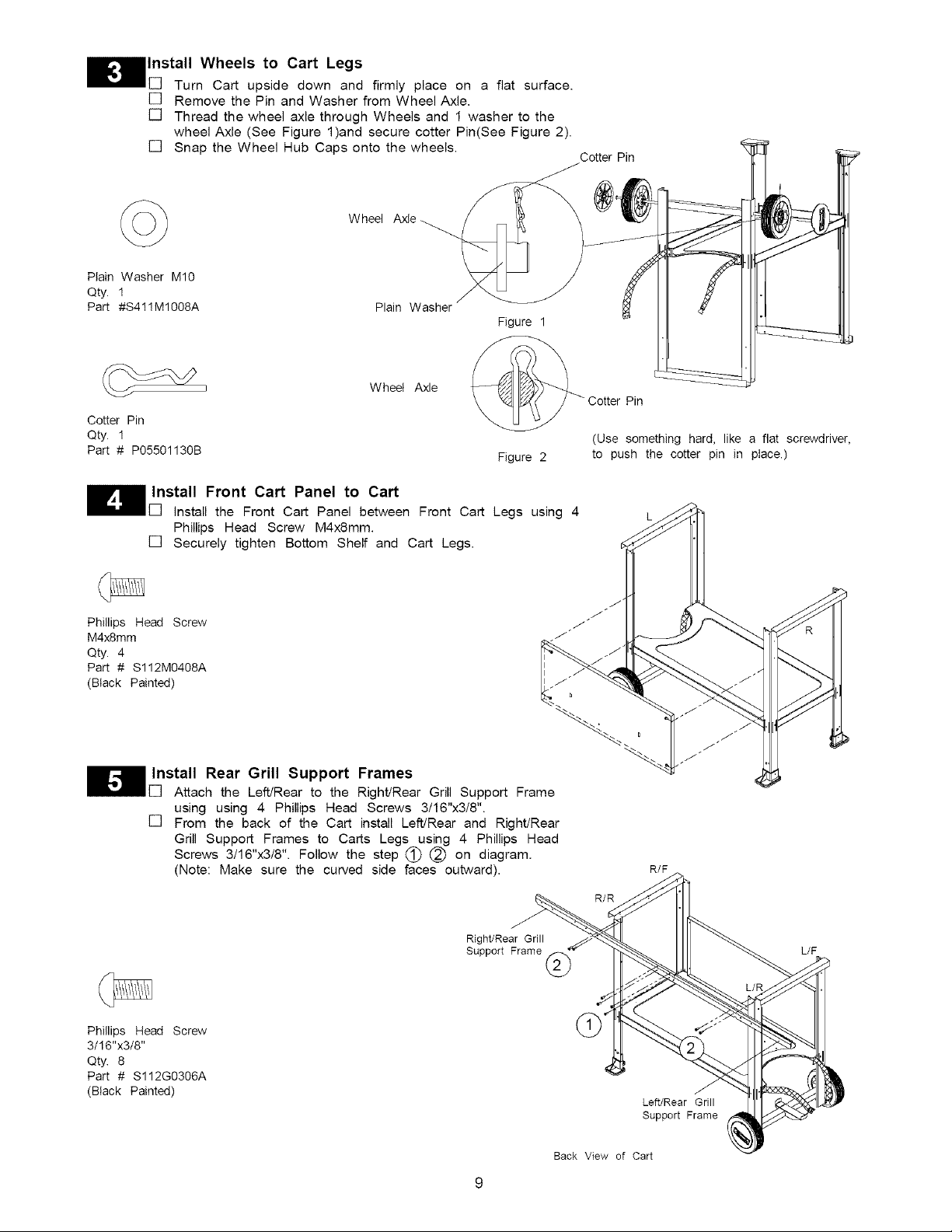
Install Wheels to Cart Legs
[] Turn Cart upside down and firmly place on a flat surface.
[] Remove the Pin and Washer from Wheel Axle.
[] Thread the wheel axle through Wheels and 1 washer to the
wheel Axle (See Figure 1)and secure cotter Pin(See Figure 2).
[] Snap the Wheel Hub Caps onto the wheels.
Wheel Axle
Plain Washer M10
Qty. 1
Part #S411M1008A Plain Washer
Cotter Pin
Figure 1
Cotter Pin
Qty. 1
Part # P05501130B
Install Front Cart Panel to Cart
install the Front Cart Panel between Front Cart Legs using 4
Phillips Head Screw M4xSmm.
[] Securely tighten Bottom Shelf and Cart Legs.
Phillips Head Screw
M4x8mm
Qty. 4
Part # S112M0408A
(Black Painted)
Install Rear Grill Support Frames
Attach the Left/Rear to the Right/Rear Grill Support Frame
using using 4 Phillips Head Screws 3/16"x3/8".
[] From the back of the Cart install Left/Rear and Right/Rear
Grill Support Frames to Carts Legs using 4 Phillips Head
Screws 3/16"x3/8". Follow the step (_ (_) on diagram.
(Note: Make sure the curved side faces outward).
Wheel Axle
Figure 2
Cotter Pin
(Use something hard, like a flat screwdriver,
to push the cotter pin in place.)
R/F
R/R
Phillips Head Screw
3/16"x3/8"
Qty. 8
Part # S112G0306A
(Black Painted)
Right/Rear Grill
Support Frame @
L/F
Left/Rear Grill
Support Frame
Back View of Cart
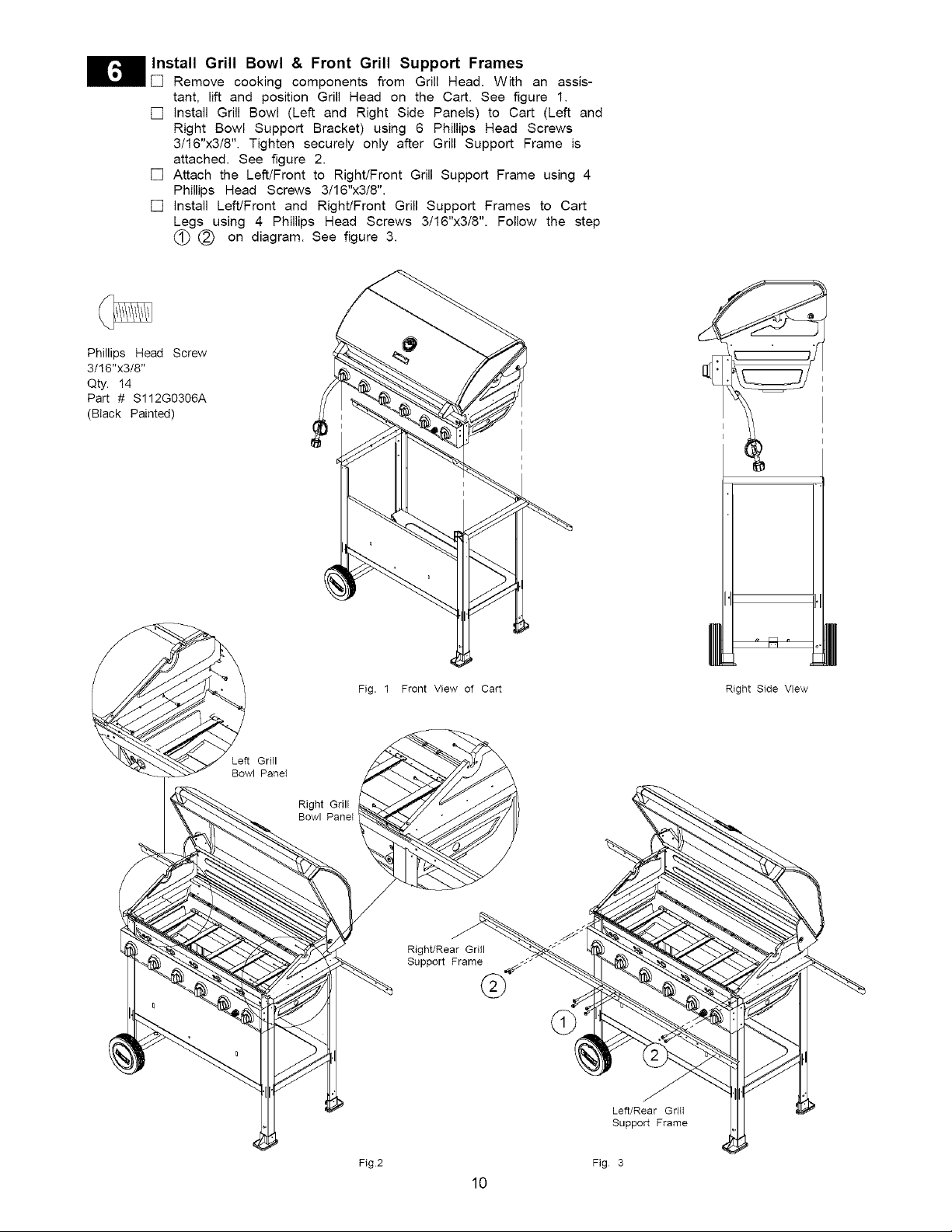
Install Grill Bowl & Front Grill Support Frames
[] Remove cooking components from Grill Head. With an assis-
tant, lift and position Grill Head on the Cart. See figure 1.
[] install Grill Bowl (Left and Right Side Panels) to Cart (Left and
Right Bowl Support Bracket) using 6 Phillips Head Screws
3/16"x3/8". Tighten securely only after Grill Support Frame is
attached. See figure 2.
[] Attach the Left/Front to Right/Front Grill Support Frame using 4
Phillips Head Screws 3/16"x3/8".
[] install Left/Front and Right/Front Grill Support Frames to Cart
Legs using 4 Phillips Head Screws 3/16"x3/8". Follow the step
(_ (_) on diagram. See figure 3.
Phillips Head Screw
3/16"x3/8"
Qty. 14
Part # S112G0306A
(Black Painted)
Bowl Panel
Right Grill
Bowl Panel
Fig. 1 Front View of Cart Right Side View
Right/Rear Grill
Support Frame
Left/Rear Griit
Support Frame
Fig2
Fig 3
10
 Loading...