

Kenmore 14116233 Owner’s Manual
OPERATOR'S MANUAL
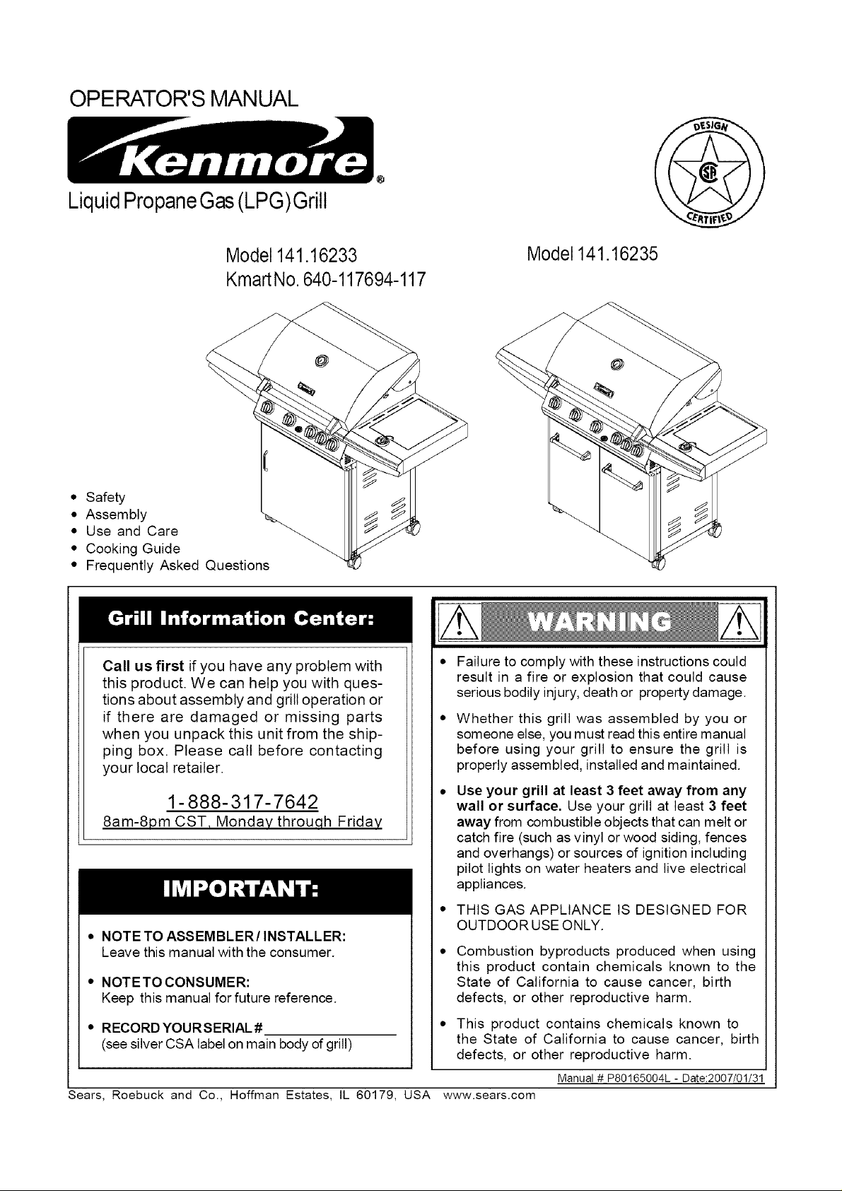
LiquidPropaneGas(LPG)Grill
Model 141.16233
KmartNo.640-117694-117
• Safety
• Assembly
• Use and Care
• Cooking Guide
• Frequently Asked Questions
Call us first if you have any problem with
this product. We can help you with ques-
tions about assembly and grill operation or
if there are damaged or missing parts
when you unpack this unit from the ship-
ping box. Please call before contacting
your local retailer.
1- 888-317-7642
8am-8pm CST, Monday throuqh Friday
• NOTE TO ASSEMBLER/INSTALLER:
Leave this manual with the consumer.
• NOTETO CONSUMER:
Keep this manual for future reference.
Model 141.16235
• Failure to comply with these instructions could
result in a fire or explosion that could cause
serious bodily injury, death or property damage.
Whether this grill was assembled by you or
someone else, you must read this entire manual
before using your grill to ensure the grill is
properly assembled, installed and maintained.
Use your grill at least 3 feet away from any
wall or surface. Use your grill at least 3 feet
away from combustible objects that can melt or
catch fire (such as vinyl or wood siding, fences
and overhangs) or sources of ignition including
pilot lights on water heaters and live electrical
appliances.
• THIS GAS APPLIANCE IS DESIGNED FOR
OUTDOOR USE ONLY.
Combustion byproducts produced when using
this product contain chemicals known to the
State of California to cause cancer, birth
defects, or other reproductive harm.
• RECORD YOURSERIAL #
(see silver CSA label on main body of grill)
Sears, Roebuck and Co., Hoffman Estates, IL 60179, USA www.sears.com
This product contains chemicals known to
the State of California to cause cancer, birth
defects, or other reproductive harm.
Manual # P80165004L - Date:2007/01/31
Primary Safety Warnings ........................... 1-3
Warranty Terms and Conditions .................. 2
Pre-Assembly Instructions .............................. 3
Part Diagrams and Lists .......................... 4-8
Assembly Instructions ............................... 9-14
LP Gas Tank Installation ...................... 15-17
Use & Care Instructions:
• Lighting Instructions ................................. 18
• Troubleshooting .......................................... 19
Cleaning and Maintenance ..................... 20-21
Cooking Guide ........................................ A1-A5
Frequently Asked Questions ................ A6-A7
One-Year Full Warranty on Kenmore Grill
If this grill fails due to a defect in material or work-
manship within one year from the date of purchase,
call 1-800-4-MY-HOME to arrange for free repair
@
(or replacement if repair proves impossible).
Additional Limited Warranty on Selected Grill
Parts
From the date of purchase for the time periods
listed below, the following specific grill parts will be
supplied free of charge if they fail to meet the
conditions described. After the first year from the
date of purchase, you pay for labor if you wish to
have them installed.
• Stainless Steel Parts - 5 years (except Stain-
less
• Steel Tube Burners - 10 years), no rust-through
• Painted Parts - 3 years, no rust-through
• Cooking grids - 2 years, no rust-through
Savor Plates - 2 years, no rust-through
All warranty coverage excludes ignitor batteries and
grill part paint loss (except as specified above) or
rusting (except for rust-through as specified above),
which are either expendable parts that can wear out
from normal use in less than a year, or are condi-
tions that can be the result of normal use, accident
or improper maintenance.
All warranty coverage is void if this grill is ever used
for commercial or rental purposes.
All warranty coverage applies only if this grill is
used in the United States.
This warranty gives you specific legal rights, and
you may have other rights which vary from state to
state.
IF YOU SMELL GAS:
1. Shut off gas to the appliance.
2 Extinguish any open flame.
3. Open lid.
4. If odor continues, keep away from
the appliance and immediately call
your gas supplier or your fire
department.
1. Do not store or use gasoline or
other flammable liquids in the vicin-
ity of this or any other appliance.
2. Any LP cylinder not connected for
use shall not be stored in the
vicinity of this or any other
appliance.
LPG grill models must be used with Liquid
Propane Gas and the regulator assembly
supplied. Natural Gas models must be used
with Natural Gas only. Any attempt to convert
the grill from one fuel type to another is
extremely hazardous and will void the
warranty.
Never use your gas grill in a garage, porch, shed,
breezeway or any other enclosed area.
Never obstruct the flow of ventilation air around
your gas grill housing.
Never disconnect the gas regulator or any gas
fitting while your grill is lit. A lit grill can ignite
leaking gas and cause a fire or explosion which
could result in property damage, personal injury or
death.
Keep gas regulator hose away from hot grill
surfaces and dripping grease. Avoid unneces-
sary twisting of hose. Visually inspect hose
prior to each use for cuts, cracks, excessive
wear or other damage. If the hose appears
damaged do not use the gas grill. Call Sears
at 1-800-4-MY-HOME ® (1-800-469-4663) for a
Kenmore replacement hose.
Sears, Roebuck and Co.
Hoffman Estates, IL 60179
© Sears Brands, LLC
Grill Installation Codes
The installation must conform with local codes or, in
the absence of local codes, with either the National
Fuel Gas Code, ANSI Z223.1/NFPA 54, Natural Gas
and Propance installation Code, CSA B149.1, or
Propane Storage and Handling Code, B149.2.
Failure to comply with these instructions may
result in a hazardous situation which, if not
avoided, may result in injury.
Spiders and small insects can spin webs and
nest in the grill ing transit and
warehousing s flow
obstruction round the
Burner T_ FIRE"
can cau_ an
unsafe {
To ;K
FIRE bes
as ;Irill.
Also do _ummer
and fall or in your
area, and if used for an
extended period
1. Remove the screw from the rear of each Burner
using a Phillips Head Screwdriver.
2. Carefully lift each Burner up and away from the
Gas Valve Orifice.
3. Check and clean Burner/Venturi Tubes for insects
and insect nests. A clogged tube can lead to a fire
beneath the grill.
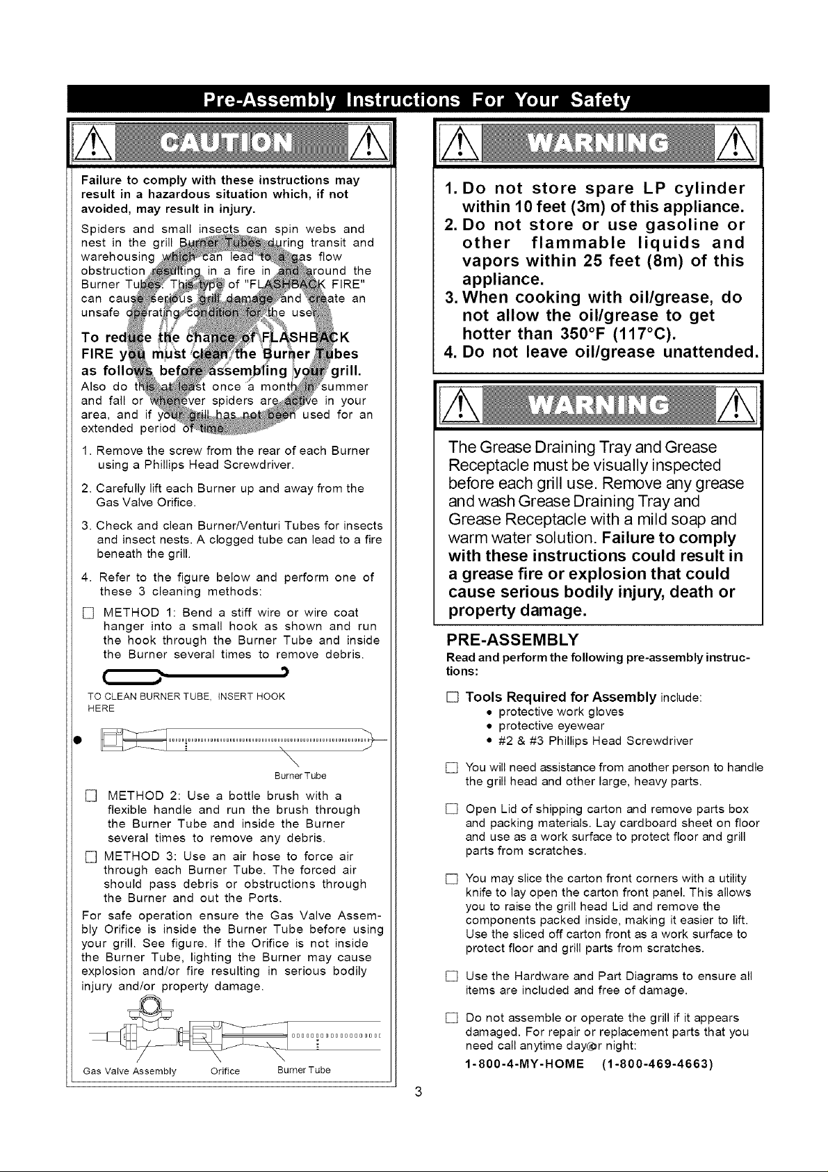
4. Refer to the figure below and perform one of
these 3 cleaning methods:
[] METHOD 1: Bend a stiff wire or wire coat
hanger into a small hook as shown and run
the hook through the Burner Tube and inside
the Burner several times to remove debris.
,)
TO CLEAN BURNER TUBE, INSERT HOOK
HERE
\
BurnerTube
[] METHOD 2: Use a bottle brush with a
flexible handle and run the brush through
the Burner Tube and inside the Burner
several times to remove any debris.
[] METHOD 3: Use an air hose to force air
through each Burner Tube. The forced air
should pass debris or obstructions through
the Burner and out the Ports.
For safe operation ensure the Gas Valve Assem-
bly Orifice is inside the Burner Tube before using
your grill. See figure. If the Orifice is not inside
the Burner Tube, lighting the Burner may cause
explosion and/or fire resulting in serious bodily
injury and/or property damage.
1. Do not store spare LP cylinder
within 10 feet (3m) of this appliance.
2. Do not store or use gasoline or
other flammable liquids and
vapors within 25 feet (8m) of this
appliance.
3. When cooking with oil/grease, do
not allow the oil/grease to get
hotter than 350°F (117°C).
4. Do not leave oil/grease unattended.
The Grease Draining Tray and Grease
Receptacle must be visually inspected
before each grill use. Remove any grease
and wash Grease Draining Tray and
Grease Receptacle with a mild soap and
warm water solution. Failure to comply
with these instructions could result in
a grease fire or explosion that could
cause serious bodily injury, death or
property damage.
PRE-ASSEMBLY
Read and perform the following pre-assembly instruc-
tions:
[] Tools Required for Assembly include:
• protective work gloves
• protective eyewear
• #2 & #3 Phillips Head Screwdriver
[]
You will need assistance from another person to handle
the grill head and other large, heavy parts.
[]
Open Lid of shipping carton and remove parts box
and packing materials. Lay cardboard sheet on floor
and use as a work surface to protect floor and grill
parts from scratches.
[]
You may slice the carton front corners with a utility
knife to lay open the carton front panel. This allows
you to raise the grill head Lid and remove the
components packed inside, making it easier to lift.
Use the sliced off carton front as a work surface to
protect floor and grill parts from scratches.
[]
Use the Hardware and Part Diagrams to ensure all
items are included and free of damage.
__j_ _ 0 [] [] 0 [] 0 [] 0 [] 0 [] 0 [] [] [] 0 [] 0 E
Gas Va+ve Assembly Orifice Burner Tube
[]
Do not assemble or operate the grill if it appears
damaged. For repair or replacement parts that you
need call anytime day(_r night:
1-800-4-MY-HOME (1-800-469-4663)
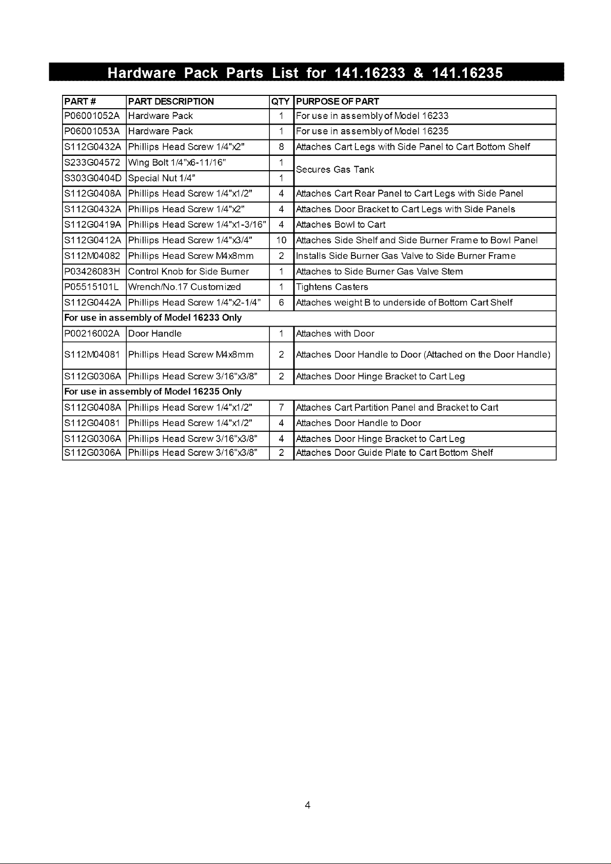
PART #
P06001052A
P06001053A
S112G0432A
$233G04572
S303G0404D Special
$112G0408A Phillips
$112G0432A Phillips
S112G0419A Phillips
S112G0412A Phillips
$112M04082 Phillips
P03426083H Control Knob for Side Burner
P05515101L Wrench/No.17 Custom ized
S112G0442A Phillips Head Screw 1/4"x2-1/4"
For use in assembly of Model 16233 Only
P00216002A Door Handle
PART DESCRIPTION
Hardware Pack
Hardware Pack
Phillips Head Screw 1/4"x2"
Wing Bolt 1/4"x6-11/16"
Nut 1/4"
Head Screw 1/4"xl/2"
Head Screw 1/4"x2"
Head Screw 1/4"xl-3/16"
Head Screw 1/4"x3/4"
Head Screw M4x8mm
QTY
PURPOSE OF PART
1
For use in assemblyof Model 16233
1
For use in assemblyof Model 16235
8
Attaches Cart Legs with Side Panel to Cart Bottom Shelf
1
Secures Gas Tank
1
4
Attaches Cart Rear Panel to Cart Legs with Side Panel
4
Attaches Door Bracket to Cart Legs with Side Panels
4
Attaches Bowl to Cart
10
Attaches Side Shelf and Side Burner Frame to Bowl Panel
2
Installs Side Burner Gas Valve to Side Burner Frame
1
Attaches to Side Burner Gas Valve Stem
1
Tightens Casters
6
Attaches weight B to underside of Bottom Cart Shelf
1 Attaches with Door
$112M04081 Phillips Head Screw M4x8mm
$112G0306A Phillips Head Screw 3/16"x3/8"
For use in assembly of Model 16235 Only
$112G0408A Phillips Head Screw 1/4"xl/2"
$112G04081 Phillips Head Screw 1/4"x1/2"
$112G0306A Phillips Head Screw 3/16"x3/8"
$112G0306A Phillips Head Screw 3/16"x3/8"
2 Attaches Door Handle to Door (Attached on the Door Handle)
2 Attaches Door Hinge Bracket to Cart Leg
7 Attaches Cart Partition Panel and Bracketto Cart
4 Attaches Door Handle to Door
4 Attaches Door Hinge Bracket to Cart Leg
2 Attaches Door Guide Plate to Cart Bottom Shelf
4
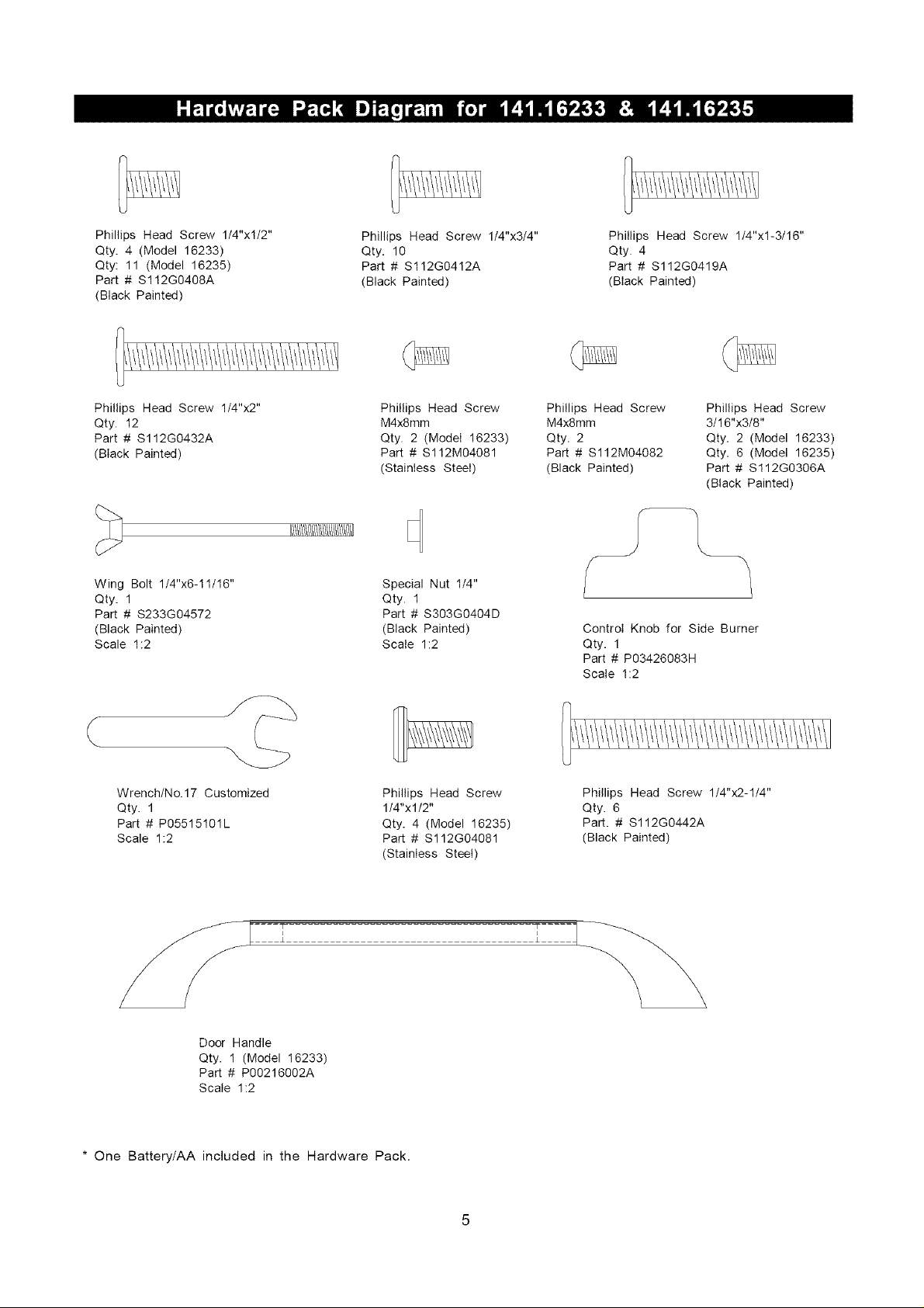
Phillips Head Screw 1/4"xl/2"
Qty. 4 (Model 16233)
Qty: 11 (Model 16235)
Part # S112G0408A
(Black Painted)
Phillips Head Screw 1/4"x3/4"
Qty. 10
Part # S112G0412A
(Black Painted)
Phillips Head Screw 1/4"xl-3/16"
Qty. 4
Part # S112G0419A
(Black Painted)
Phillips Head Screw 1/4"x2"
Qty. 12
Part # S112G0432A
(Black Painted)
Wing Bolt 1/4"x6-11/16"
Qty. 1
Part # $233G04572
(Black Painted)
Scale 1:2
Wrench/No.17 Customized
Qty. 1
Part # P05515101L
Scale 1:2
Phillips Head Screw
M4x8mm
Qty. 2 (Model 16233)
Part # $112M04081
(Stainless Steel)
I/!/!///!///////!/!/!/!/!/!/!1]
Special Nut 1/4"
Qty. 1
Part # S303G0404D
(Black Painted)
Scale 1:2
Phillips Head Screw
1/4"xl/2"
Qty. 4 (Model 16235)
Part # $112G04081
(Stainless Steel)
Phillips Head Screw
M4x8mm
Qty. 2
Part # $112M04082
(Black Painted)
Control Knob for Side Burner
Qty. 1
Part # P03426083H
Scale 1:2
Phillips Head Screw 1/4"x2-1/4"
Qty. 6
Part. # S112G0442A
(Black Painted)
Phillips Head Screw
3/16"x3/8"
Qty. 2 (Model 16233)
Qty. 6 (Model 16235)
Part # S112G0306A
(Black Painted)
J L
Door Handle
Qty. 1 (Model 16233)
Part # P00216002A
Scale 1:2
* One Battery/AA included in the Hardware Pack.
V
29
28
14
24
B4
B5
2E
B6
4 3_
BIO
13
1\
2A
B7_
26
20
54
10
>
/ B9
B8
39
43
46
32
41
33
42
43
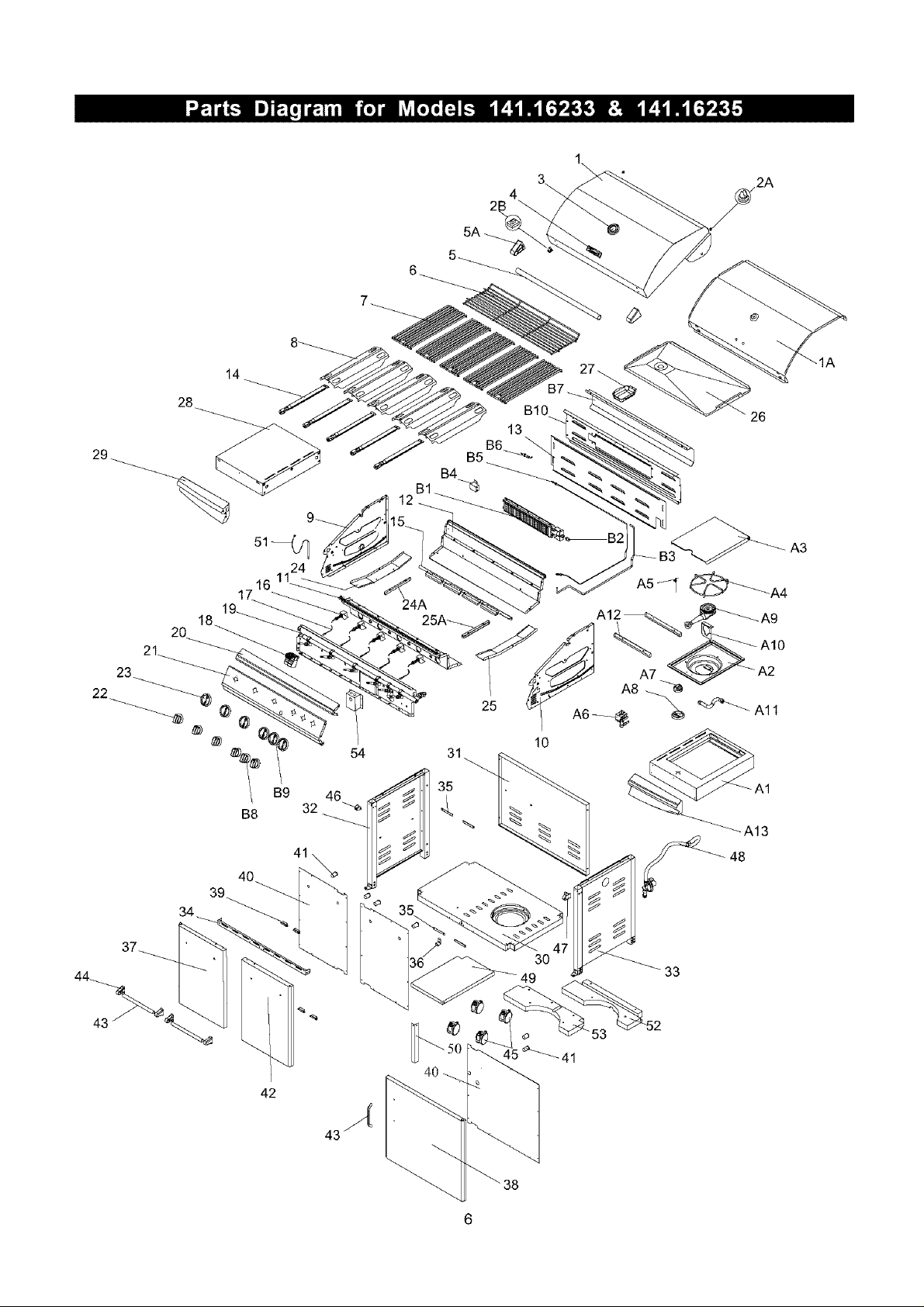
KEY
1
1A
2A
2B
3
4
5
5A
6
7
8
9
10
11
12
13
14
15
16
17
18
19
20
21
22
23
24
24A
25
25A
26
27
28
29
3O
31
32
33
34
35
36
37
38
39
4O
41
42
43
44
45
46
PART DESCRIPTION
Lid
Lid Trim Plate
Protective Pad
Protective Pad
Temperature Gauge
Name Plate
Lid Handle
Lid Handle Bracket
Cooking Rack/Secondary
Cooking Grid
Savor Plate
Bowl Panel, Left
Bowl Panel, Right
Bowl Panel, Front
Bowl Panel, Rear
Bowl Panel Rear/Upper
Burner/Main
Burner Bracket
Gas Collector Boxwith Electrode
Electric Wire Set
Electric Ignitor, 6-Port
Gas Valve/Manifold Assembly
Decorative Front Cover
Control Panel
Control Knob for Main Burner
Control Knob Seat
Grease Draining Plate, Left
Grease Tray Track, Left
Grease Draining Plate, Right
Grease TrayTrack, Right
Grease Draining Tray
Grease Receptacle
Side Shelf, Left
Decorative Panel for Side Shelf, Left
Cart Bottom Shelf
Cart Rear Panel
Cart Legs with Side Panel, Left
Cart Legs with Side Panel, Right
Cart Bracket, Front
Door Stop Plate
Door Guide Plate
Door, Left
Door
Door Magnet
Door Trim Plate
Door Spacer
Door, Right
Door Handle
Door Handle Bracket
Caster, 3 in., with Brake
Door Hinge Bracket, Left
16233
PART #
P0014607EA
P0011452QJ
P055180011
P055180041
P00601071A
P00410041C
P00205084B
P00303062A
P01505008E
P01615029H
P01708034E
P00720734A
P00721774A
P00738669A
P00725739A
P06905047B
P02008029A
P02204172E
P02609008F
P02615093A
P02502075C
Y0060389
P02907867S
P02907857S
P03419023H
P03415263L
P06901010B
P06901012B
P06901011B
P06901013B
P02706237B
P02701087B
P01102050C
P07503006A
P01002059D
P07702061B
P07617005B
P07618006B
P03305027D
P05510002B
P04301027J
P05523002K
P07510015N
P06801010G
P00216002A
P05106004A
QTY
16235
PART #
1
1
2
2
1
1
1
2
1
4
4
1
1
1
1
1
4
1
4
1
1
1
1
1
4
4
1
1
1
1
1
1
1
1
1
1
1
1
1
2
P0014704EA
P0011453QJ
P055180011
P055180041
P00601071A
P00410041C
P00205085B
P00303062A
P01506005G
P01615029H
P01708034E
P00720734A
P00721774A
P00738659A
P00725729A
P06905048B
P02008029A
P02205082E
P02609008F
P02615092A
P02502075C
Y0060390
P02909687S
P02909677S
P03419103H
P03415263L
P06901010B
P06901012B
P06901011B
P06901013B
P02707074A
P02701087B
P01102050C
P07503006A
P01004055D
P07702060B
P07617004B
P07618006B
P03305026J
P05510002B
P05510006A
P04302037J
1
2
1
2
P05523002K
P07510003N
P06801010G
P04303037J
1
P00203023B
P00303073A
4
P05106004A
P03313004D
QTY
1
1
2
2
1
1
1
2
1
5
5
1
1
1
1
1
5
1
5
1
1
1
1
1
5
5
1
1
1
1
1
1
1
1
1
1
1
1
1
4
1
1
4
2
4
1
2
4
4
1

KEY
47
48
49
5O
51
52
53
54
A1
A2
A3
A4
A5
A6
A7
A8
A9
A10
A11
A12
A13
B1
B2
B3
B4
B5
B6
B7
B8
B9
B10
PART DESCRIPTION
Door Hinge Bracket, Right
Regulator with Hose
Cart Partition Panel. Left
Cart Partition Panel Bracket, Left
Lighting Stick Assembly
Weight A
Weight B
Electric Ignitor Protector
Side Burner Frame
Side Burner Body
Side Burner Lid
Side Burner Pot Support
Side Burner Electrode
Side Burner Gas Valve Assembly
Control Knob for Side Burner
Control Knob Seat
Side Burner with Brass Ring
Side Burner Bracket
Side Burner Connection Hose
Side Burner Body Bracket
Decorative Panel for Side Burner Frame
Back Burner Assembly
Back Burner Orifice
Back Burner Extension Tube
Back Burner Gas Collector Box
Back Burner Thermocouple
Back Burner Electrode
Back Burner Wind Shied
Control Knob for Back Burner
Control Knob Seat
Back Burner Frame
Hardware Pack
Operator's Manual
16233 16235
PART # QTY PART #
P03313002D 1 P03313002D
P03601038A 1 P03601038A
-- __ P07512001D
-- __ P03303014J
P05313010B 1 P05313010B
P05344006Q 1 P05344006Q
P05344005Q 1 P05344005Q
P03343005A 1 P03343005A
P01104040C 1 P01104040C
P02302012D 1 P02302012D
P00115345K 1 P00115345K
P00805013B 1 P00805013B
P02607053L 1 P02607053L
Y0060397 1 Y0060397
P03426083H 1 P03426193H
P03415263L 1 P03415263L
P02002055D 1 P02002055D
P02215072E 1 P02215072E
P03710002F 1 P03710002F
P03305011D 2 P03305011D
P07502016A 1 P07502016A
P02007066A 1 P02007066A
P06509026A 1 P06509026A
P03717043A 1 P03717041A
P02621001K 1 P02621001K
P05305001A 1 P05305006A
P02614009C 1 P02614012C
P06905018B 1 P06905045B
P03419093H 1 P03419113H
P03415263L 1 P03415263L
P02011051E 1 P02011050E
P06001052A 1 P06001053A
P80165004L 1 P80165004L
QTY
1
1
1
1
1
1
1
1
1
1
1
1
1
1
1
1
1
1
1
2
1
1
1
1
1
1
1
1
1
1
1
1
1
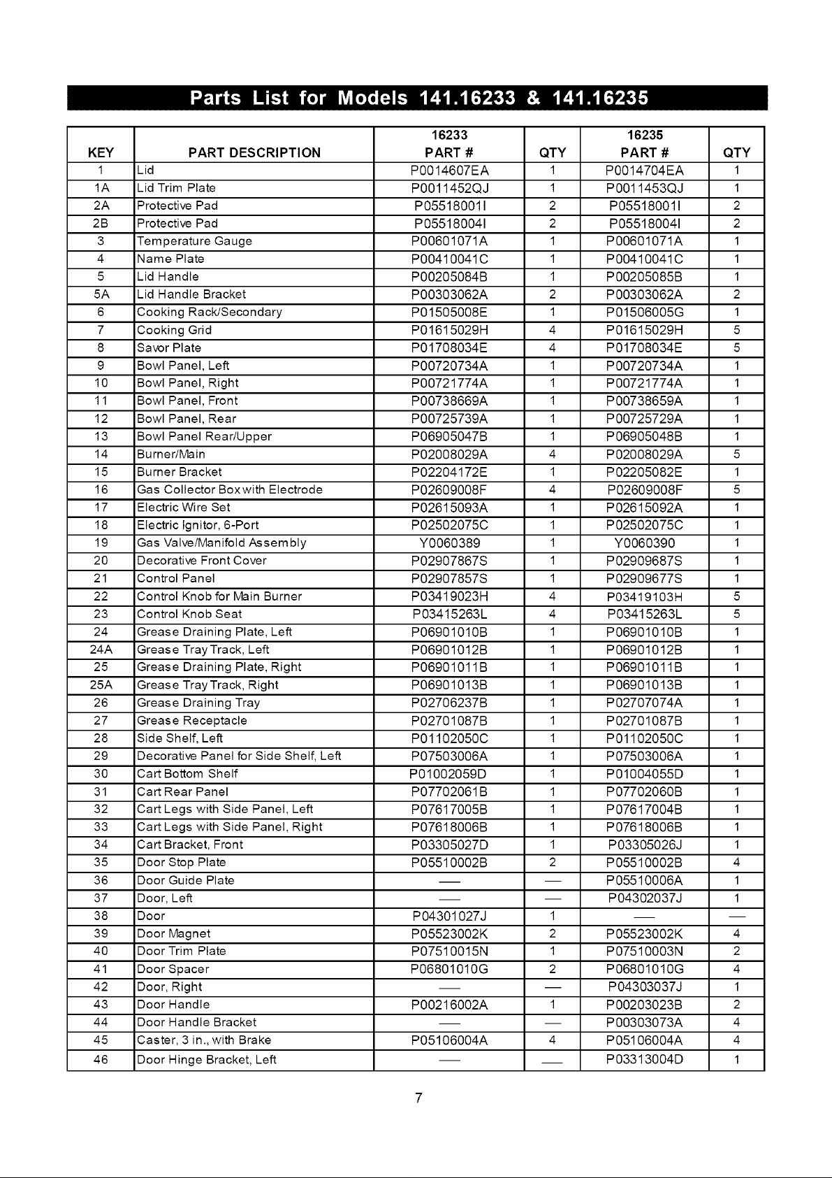
For the repair or replacement parts you need:
Call anytime 1-800-4-MY-HOME® (1-800-469-4663)
To obtain the correct replacement parts for your gas grill, please refer to the part numbers in this parts
list. The following information is required to ensure you receive the correct parts:
1. Model and Serial Number (see CSA label on grill)
2. Part Number
3. Part Description
4. Quantity of parts needed
Important: Use only Kenmore replacement parts. The use of any part that is not a Kenmore replacement
part can be dangerous and will also void your product warranty. Keep this Operator's Manual for
convenient referral and for part replacement.
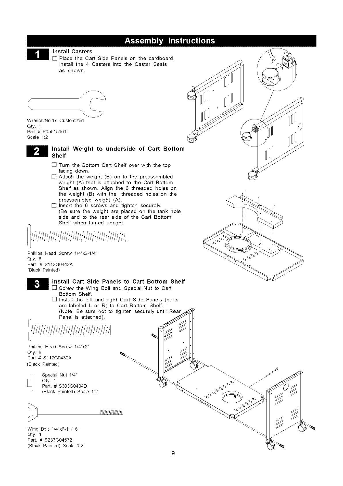
Install Casters
[] Place the Cart Side Panels on the cardboard.
Install the 4 Casters into the Caster Seats
as shown.
Wrench/No.17 Customized
Qty. 1
Part # P05515101L
Scale 1:2
Install Weight to underside of Cart Bottom
Shelf
[] Turn the Bottom Cart Shelf over with the top
facing down.
[] Attach the weight (B) on to the preassembled
weight (A) that is attached to the Cart Bottom
Shelf as shown. Align the 6 threaded holes on
the weight (B) with the threaded holes on the
preassembled weight (A).
[] Insert the 6 screws and tighten securely.
(Be sure the weight are placed on the tank hole
side and to the rear side of the Cart Bottom
Shelf when turned upright.
Phillips Head Screw 1/4"x2-1/4"
Qty. 6
Part. # S112G0442A
(Black Painted)
H nstall Cart Side Panels to Cart Bottom Shelf
Phillips Head Screw 1/4"x2"
Qty. 8
Part # S112G0432A
(Black Painted)
[] Screw the Wing Bolt and Special Nut to Cart
Bottom Shelf.
[] Install the left and right Cart Side Panels (parts
are labeled L or R) to Cart Bottom Shelf.
(Note: Be sure not to tighten securely until Rear
Panel is attached).
Specia! Nut 1/4"
Qty. 1
Part. # S303G0404D
(Black Painted) Scale 1:2
_/!/!/!/!/!/!/!/!/!/!/!/!/!/!1
Wing Bolt 1/4"x6-11/16"
Qty. 1
Part. # S233G04572
(Black Painted) Scale 1:2
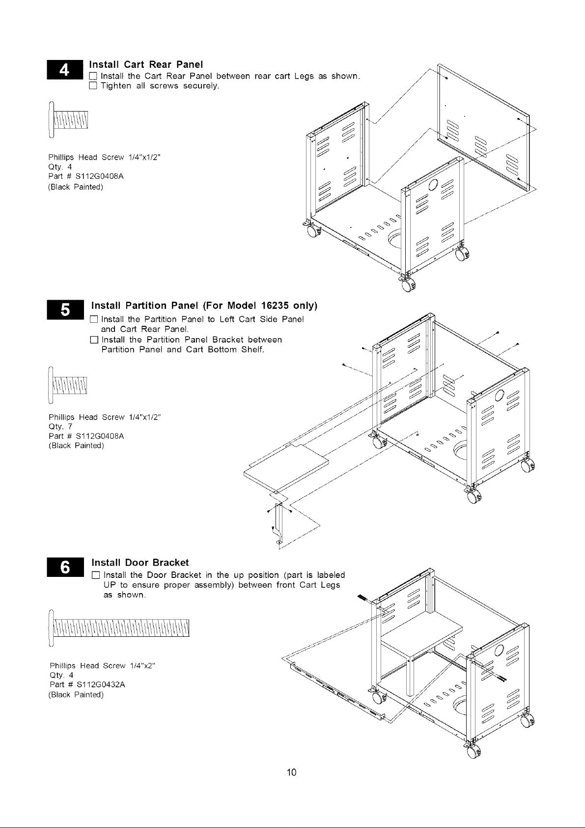
Install Cart Rear Panel
[] Install the Cart Rear Panel between rear cart Legs as shown.
[] Tighten all screws securely.
Phillips Head Screw 1/4"xl/2"
Qty. 4
Part # S112G0408A
(Black Painted)
Install Partition Panel (For Model 16235 only)
[] install the Partition Panel to Left Cart Side Panel
and Cart Rear Panel.
[] install the Partition Panel Bracket between
Partition Panel and Cart Bottom Shelf.
,/
//
//
/
,/
,/
/
/
/
/
/
,/
//
/
/
/
/
/
/
Phillips Head Screw 1/4"xl/2"
Qty. 7
Part # S112G0408A
(Black Painted)
H nstall Door Bracket
[] Install the Door Bracket in the up position (part is labeled
UP to ensure proper assembly) between front Cart Legs
as shown. ,_.
Phillips Head Screw 1/4"x2"
Qty. 4
Part # S112G0432A
(Black Painted)
10
 Loading...