

Kenmore 141.16225 Owner's Manual
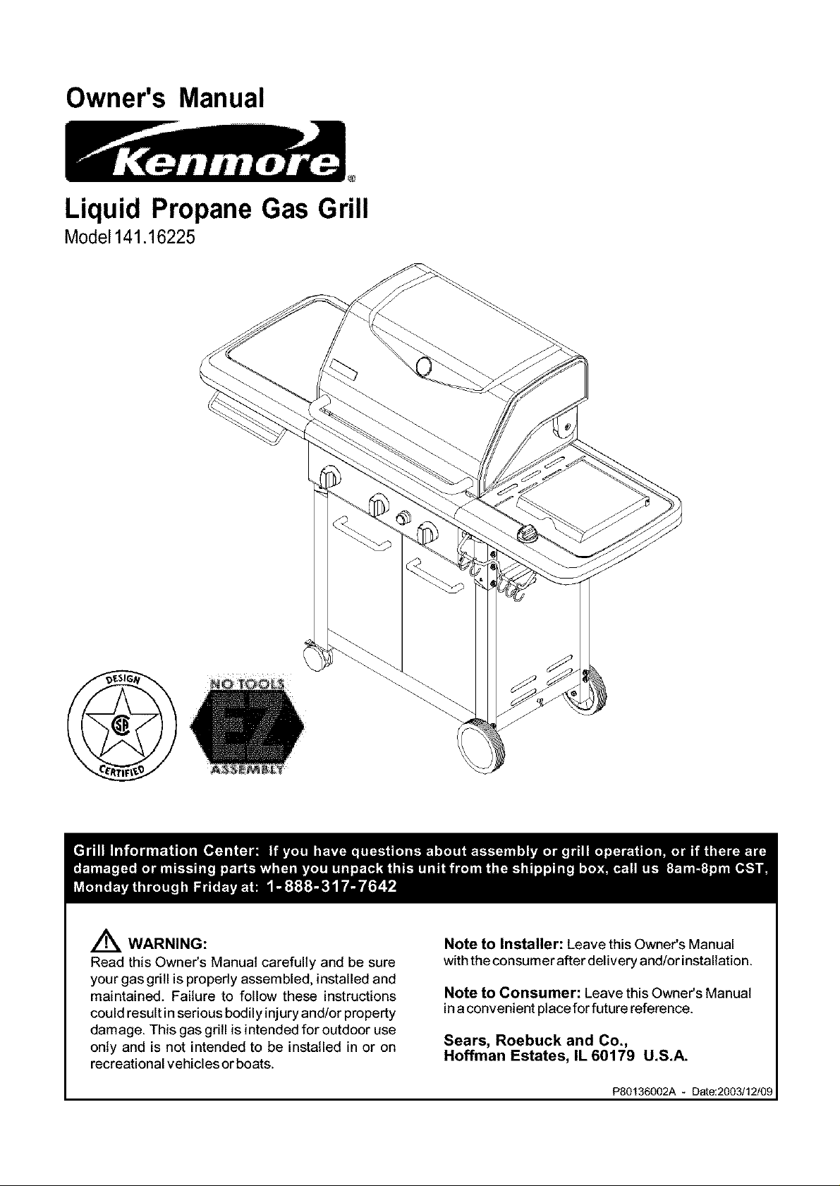
Owner's Manual
@
Liquid Propane Gas Grill
Model141.16225
A WARNING:
Read this Owner's Manual carefully and be sure
your gas grill is properly assembled, installed and
maintained. Failure to follow these instructions
could result in serious bodily injury and/or property
damage. This gas grill is intended for outdoor use
only and is not intended to be installed in or on
recreational vehicles or boats.
Note to Installer: Leave this Owner's Manual
withthe consumer after delivery and/or installation.
Note to Consumer: Leave this Owner's Manual
in aconvenient place for future reference.
Sears, Roebuck and Co.,
Hoffman Estates, IL 60179 U.S.A.
P80136002A - Date:2003/12/09
Warranty ..................................................... 2
Safety Instructions ..................................... 2
Hardware .................................................... 5
Parts Diagram and Lists ........................ 7
Assembly Instructions .............................. 10
Lighting Instructions ................................ 20
Cleaning and Maintenance Instructions .... 22
Frequently Asked Questions .................. 24
Cooking Instructions .............................. A-1
Cooking Guide and Recipes .............. A-2
Full 1-Year Warranty on Grill
For one year from the date of purchase Sears will
repair or replace, at our option, any grill part
(except for paint loss, rusting and ignitor battery)
that is defective in material or workmanship.
Limited Warranty on Selected Grill Parts
From one year after the date of purchase for the
designated time periods listed below, Sears will
replace the following grill parts if they are defective
in material or workmanship. You will be charged for
labor.
• 1 Year: Cast Iron Burners
• 2 Years: All Other Grill Parts (except flame tamers,
cooking grids and ignitor battery)
Warranty Service
Warranty service is available by contacting the
nearest Sears Service Center at 1-800-4-MY-HOME ®
Warranty Restrictions
• This warranty is void if grill is used for commer-
cial or rental purposes.
• This grill is for use with Liquid Propane (LP)
gas only. Any attempt to convert this grill to
natural gas is dangerous and will void your
product warranty.
• This warranty applies only when the grill is
used in the United States.
• This warranty gives you specific legal rights,
and you may also have other rights which vary
from state to state.
Sears, Roebuck and Co., Dept. 817WA,
Hoffman Estates, IL 60179
,4kWARNING
Combustion byproducts produced when using
this product contain chemicals known to the
State of California to cause cancer, birth
defects, or other reproductive harm.
Z_WARNING
Failure to comply with these instructions
could result in a fire or explosion that
could cause serious bodily injury, death, or
property damage.
Z_WARNING
Your grill will get very hot. Never lean over
the cooking area while using your grill. Do not
touch cooking surfaces, grill housing, Lid or any
other grill parts while the grill is in operation, or
until the grill has cooled down after use.
Failure to comply with these instructions
may result in serious bodily injury.
Z_WARNING
(a) Do not store a spare LP-gas cylinder
under or near this appliance;
(b) Never fill the cylinder beyond 80 percent
full; and
(c) If the information in "(a)" and "(b)" is not
followed exactly, a fire causing death or
serious injury may occur.
FOR YOUR SAFETY
1. Do not store or use gasoline or other flam-
mable material and liquids in the vicinity of this
or any other appliance.
2. ALP cylinder not connected for use must not
be stored in the vicinity of this or any other
appliance.
FOR YOUR SAFETY
If you smell gas:
1. Shut off gas to the appliance.
2. Extinguish any open flame such as candle,
cigarette, lighter, etc., that could cause gas to
ignite.
3. Open the Grill Lid.
4. If odor continues, immediately call your gas
supplier or your fire department.
IMPORTANT: Your Kenmore LP Gas Grill cannot
be converted to use Natural Gas. Attempting to do
so is extremely hazardous and will also void the
grill warranty.
Grill Installation Codes
The installation must conform with local codes or, in
the absence of local codes, with either the National
Fuel Gas Code, ANSI Z223.1/NFPA 54, or CAN/
CGA-B149.1, Natural Gas and Propane Installation
Code.
2 © Sears, Roebuck and Co.
Correct LP Gas Tank Use
LP gas grill models are designed for use with a
standard 20 lb. Liquid Propane Gas (LP gas) tank,
not included in grill box. Never connect your gas
_rill to an LP gas tank that exceeds this capacity.
tank of approximately 12 inches in diameter by
18-1/2 inches high is the maximum size LP gas
tank to use. You must use an "OPD" gas tank
which offers a listed Overfill Prevention Device.
This safety feature prevents tank from being overfilled
which can cause malfunction of LP gas tank,
regulator and/or grill.
The LP gas tank must be constructed and marked
in accordance with the Specifications for LP-Gas
Cylinders of the U.S. Department of Transportation
(D.O.T.) or the National Standard of Canada, CAN/
CSA-B339, Cylinders, Spheres and Tubes for Trans-
portation of Dangerous Goods; and Commission, as
applicable.
1. The LP gas tank has a shutoff valve, termi-
nating in an LP gas supply tank valve outlet,
that is compatible with a Type 1 tank con-
nection device. The LP gas tank must also
have a safety relief device that has a direct
connection with the vapor space of the tank.
2. The tank supply system must be arranged
for vapor withdrawal.
3. The LP gas tank used must have a collar
to protect the tank valve.
• LP gas tanks must be stored outdoors in a
well-ventilated area and out of the reach of
children. Disconnected LP gas tanks must not
be stored in a building, garage or any other
enclosed area.
• When your gas grill is not in usa the gas
must be turned off at the LP gas tank.
• The regulator and hose assembly can be seen
after opening the doors (if applicable), must be
inspected before each use of the grill. If there
is excessive abrasion or wear or if the hose is
cut, it must be replaced prior to the grill being
used again.
• Keep the gas regulator hose away from hot
grill surfaces and dripping grease. Avoid unnec-
essary twisting of hose. Visually inspect hose
prior to each use for cuts, cracks, excessive
wear or other damage. If the hose appears
damaged do not use the gas grill. Call Sears
at 1-800-4-MY-HOME®(1-800-469-4663) for a
Sears authorized replacement hose.
• Never light your gas grill with the lid closed or
before checking to ensure the burner tubes are
fully seated over the gas valve orifices.
• Never allow children to operate your grill. Do
not allow children to play near your grill.
Proper Placement and Clearance of Grill
Never use your gas grill in a garage, porch, shed,
breezeway or any other enclosed area. Your gas grill is
to be used outdoors only, at least 24 inches from the
back and side of any combustible surface. Do not
locate this appliance under overhead unprotected
combustible surfaces. Do not obstruct the flow of
ventilation air around the gasgrill housing.
This outdoor gas grill is not intended to be installed in
or on recreational vehicles and/or boats.
• Never connect an unregulated LP gas tank to
your gas grill. The gas regulator assembly
supplied with your gas grill is adjusted to have
an outlet pressure of 11" water column (W.C.)
for connection to an LP gas tank.
• Only use the regulator and hose assembly
supplied with your gas grill. Replacement
regulators and hose assemblies must be those
specified by Sears.
• Have your LP gas tank filled by a reputable
propane gas dealer and visually inspected and
re-qualified at each filling.
• Never fill the gas tank beyond 80% full.
Have your propane gas dealer check the
release valve after every filling to ensure that it
remains free of defects.
• Always keep LP gas tanks in upright position.
Do not store (or use) gasoline or other flammable
vapors and liquids in the vicinity of this gas grill.
• LP gas tanks not connected for use must NOT be
stored on bottom shelf or in the vicinity of this or
any other gas grill.
• Do not subject the LP gas tank to excessive heat.
• Never store an LP gas tank indoors. If you
store your gas grill in the garage or other indoor
location, always disconnect the LP gas tank
first and store it safely outside.
Z WARNING
If you smell gas:
• Shut off gas supply to the gas grill.
• Turn the Control Knobs to OFF position.
• Extinguish any open flame such as candle,
cigarette, lighter, etc., that could cause gas
to ignite.
• Open the Grill Lid.
• Get away from the LP gas tank.
• Do not try to fix the problem yourself.
• If odor continues or you have a fire you
cannot extinguish, call your fire depart-
ment. Do not call near the LP gas tank
because your telephone is an electrical
device and could create a spark resulting
in fire and/or explosion.
NOTE: The normal flow of gas through the
regulator and hose assembly can create a
humming noise. A low volume of noise is
perfectly normal and will not interfere with
operation of the grill. If humming noise is
loud and excessive you may need to purge
air from the gas line or reset the regulator
excess gas flow device. This purging proce-
dure should be done every time a new LP
gas tank is connected to your grill. For help
call the Grill Information Center for assis-
tance, 8am - 8pm CST, Monday through
Friday 1-888-317-7642.
CAUTION: Spiders and small insects occa-
sionally spin webs or make nests in the grill
Burner Tubes during transit and warehousing.
These webs can lead to a gas flow obstruc-
tion which could result in a fire in and around
the Burner Tubes. This type of fire is known
as a "FLASHBACK" and can cause serious
damage to your grill and create an unsafe
operating condition for the user.
To reduce the chance of "FLASHBACK", you
must clean the burner tubes before assem-
bling your grill, and at least once a month in
late summer or early fall when spiders are
most active. Also perform this Burner Tube
cleaning procedure if your grill has not been
used for an extended period of time.
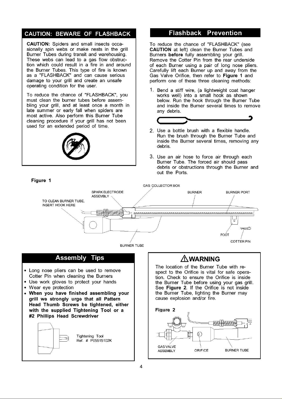
To reduce the chance of "FLASHBACK" (see
CAUTION at left) clean the Burner Tubes and
Burners before fully assembling your grill.
Remove the Cotter Pin from the rear underside
of each Burner using a pair of long nose pliers.
Carefully lift each Burner up and away from the
Gas Valve Orifice, then refer to Figure 1 and
perform one of these three cleaning methods:
.
Bend a stiff wire, (a lightweight coat hanger
works well) into a small hook as shown
below. Run the hook through the Burner Tube
and inside the Burner several times to remove
any debris.
[ J
Use a bottle brush with a flexible handle.
.
Run the brush through the Burner Tube and
inside the Burner several times, removing any
debris.
.
Use an air hose to force air through each
Burner Tube. The forced air should pass
debris or obstructions through the Burner and
out the Ports.
Figure 1
SPARKELECTRODE
TO CLEAN BURNER TUBE,
INSERT HOOK HERE
\\\_\
\
ASSEMBLY \\
\
BURNER TUBE
Long nose pliers can be used to remove
Cotter Pin when cleaning the Burners
Use work gloves to protect your hands
Wear eye protection
When you have finished assembling your
grill we strongly urge that all Pattern
Head Thumb Screws be tightened, either
with the supplied Tightening Tool or a
#2 Phillips Head Screwdriver
GAS COLLECTOR BOX
/
BURNER BURNERPORT
FOOT
Z WARNING
The location of the Burner Tube with re-
spect to the Orifice is vital for safe opera-
tion. Check to ensure the Orifice is inside
the Burner Tube before using your gas grill.
See Figure 2. If the Orifice is not inside
the Burner Tube, lighting the Burner may
cause explosion and/or fire.
Figure 2
COTTERPIN
Tightening Tool
Ref. # P05515102K
GAS VALVE I \
ASSEMBLY ORiFiCE BURNER TUBE
\
4

Thefollowingtableillustratesa breakdownof thehardwarepack.It highlightswhatcomponentsare used
in the variousstagesof assembly.
Refi
S211G06352
$431 M08152
$313G06082
$132G04082
$135G04332
$132G04082
$132G04082
$135G04332
P05318022B
$132G04082
$132G04121
$135G04101
$132G04122
$132G04122
$233G04382
P05301001A
Component Qty.
Wheel Bolt 3/8"x3-3/8" 2
Spring Washer 2
Nut 3/8" 2
Pattern Head Screw 1/4"xl/2" 6
Pattern Head Screw 1/4"x2-3/4" 8
Pattern Head Screw 1/4"xl/2" 4
Pattern Head Screw 1/4"xl/2" 8
Pattern Head Screw 1/4"x2-3/4" 4
Door Stop/Magnet 2
Pattern Head Screw 1/4"xl/2" 4
Pattern Head Screw 1/4"x3/4" 4
PatternHeadParUy-ThreadedScrew1/4"x5/8" 4
Pattern Head Screw 1/4"x3/4" 4
Pattern Head Screw 1/4"x3/4" 4
Wing Bolt 1/4"x4-3/8" 1
Battery/AA 1
Purpose of Components
Install Wheels To Cart Legs
Attaches
Attaches
Attaches
Attaches
Attaches
Attaches
Attaches
Attaches
Attaches
Attaches
Attaches
Secure Gas Tank
Powers The Electric Ignitor
Foldable Cart Legs
Cart Legs To Cart Bottom Shelf
Cart Rear Panel To Cart
Cart Side Panels To Cart
Door Bracket To Cart
To Cart
Magnetic Door Stop To Cart
Door Handles To Doors
Doors To Cart
Left Side Shelf To Grill Head
Side Burner Frame To Grill Head
P05515101L
P05313023B
$132M04082
P05515102K
P03426061 C
PO5501010B
S132M04082
S411M04122
S132M04082
Already installed in the Tool Holder Kit & Towel Rack
$132Mg5082 Pattern Head Screw M5x8mm 2
$411Mg5136 Plain Washer M5 2
$132Mg5082 Pattern Head Screw M5x8mm 2
$411Mg5136 Plain Washer M5 2
Wrench/No.17 Customized 1
Lighting Stick 1
Pattern Head Screw M4x8mm 1
Tightening Tool 1
Control Knob 1
Cotter Pin 1
Pattern Head Screw M4x8mm 2
Plain Washer M4 2
Pattern Head Screw M4x8mm 2
Tighten Caster & Wheel Bolt
Attaches to Bowl Support Bracket, Left
Attaches to Bowl Support Bracket, Left
Allows you to tighten Pattern Head Thumb Screws
after assembly
Install To Side Burner Gas Valve Stem
Secure To Side Burner
Attaches To Side Burner Gas Valve Bracket
Attaches To Side Burner Gas Valve Bracket
Attaches To Left & Right Bowl Panel for Bowl Wind
Shield
Attaches Towel Rack to Left Side Shelf
Attaches Tool Holder to Side Burner Frame
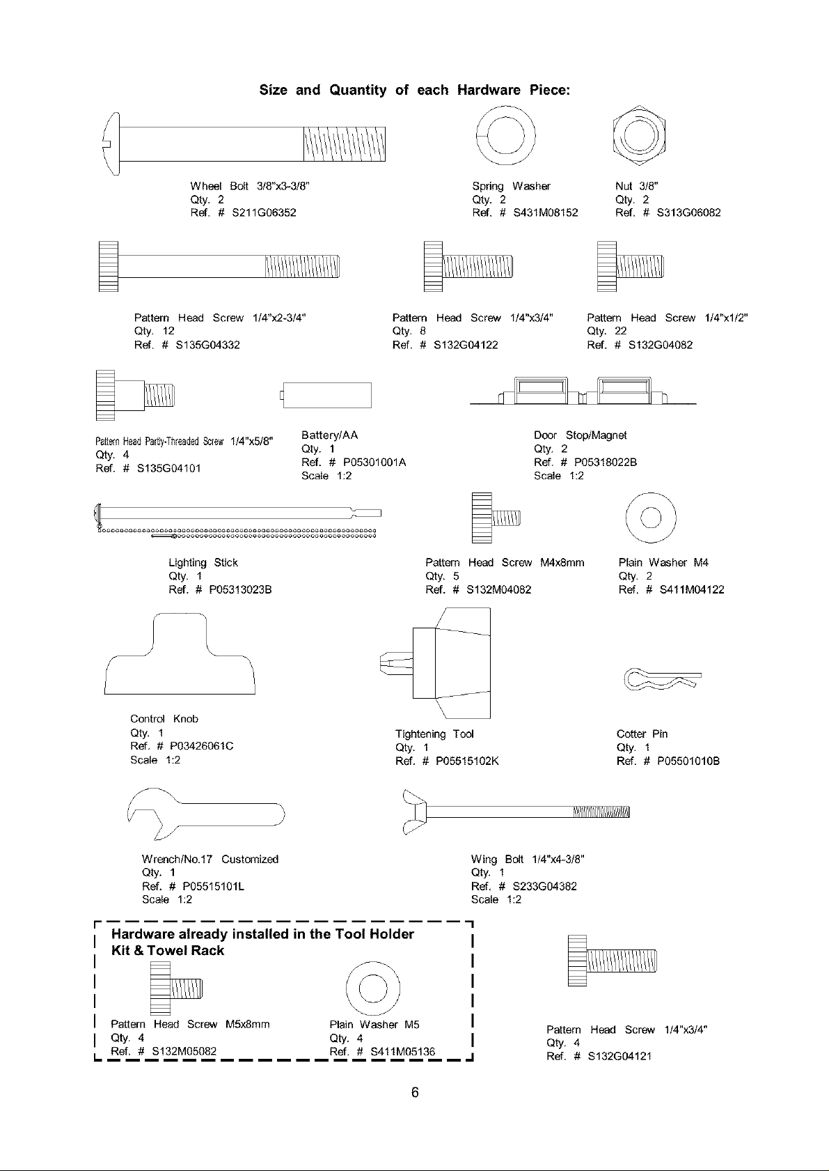
Size and Quantity of each Hardware Piece:
Wheel Bolt 3/8"x3-3/8"
Qty, 2
Ref. # $211G06352
Pattern Head Screw 1/4"x2-3/4"
Qty, 12
Ref. # $135G04332
PatternHeadPartly.ThreadedScrew1/4"x5/8"
Qty. 4
Ref. # $135G04101
Lighting Stick
Qty. 1
Ref. # P05313023B
Battery/AA
Qty. 1
Ref. # P05301001A
Scale 1:2
Spdng Washer
Qty, 2
Ref. # $431M08152
Pattern Head Screw 1/4"x3/4"
Qty. 8
Ref. # $132G04122
Door Stop/Magnet
Qty. 2
Ref. # P05318022B
Scale 1:2
Pattern Head Screw M4xSmm
Qty. 5
Ref. # $132M04082
Nut 3/8"
Qty. 2
Ref. # $313G06082
Pattern Head Screw 1/4"xl/2"
Qty. 22
Ref. # $132G04082
Plain Washer M4
Qty, 2
Ref. # $411M04122
\
Ceett_l Knob
Qty, 1
Ref, # P03426061C
Scale 1:2
Wrench/No,17 Customized
Qty. 1
Ref. # P05515101L
Scale 1:2
Hardware already installed in the Tool Holder
Kit & Towel Rack
Pattern Heed Screw M5x8mm
Qty. 4
Ref. # $132M05082
I,.
Plain Washer M5
Qty. 4
Ref. # $411M05136
Tightening Tool
Qty. 1
Ref. # P05515102K
Wing Bolt 1/4"x4-3/8"
Qty, 1
Ref, # $233G04382
Scale 1:2
Cotter Pin
Qty, 1
Ref. # P05501010B
Pattern Head Screw 1/4"x3/4"
Qty, 4
Ref. # $132G04121
6
5
7
6
8_
1
4,(L)
45
46_.
36_
29
50
49
56
\
7
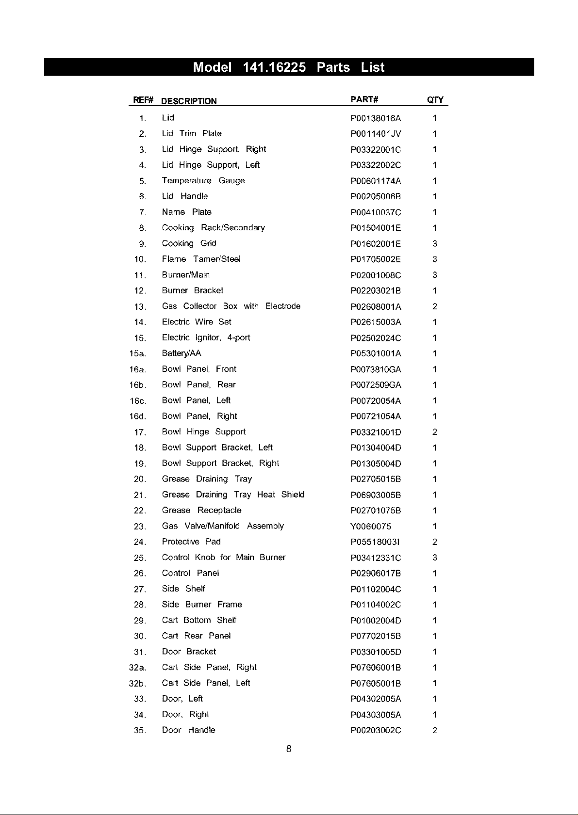
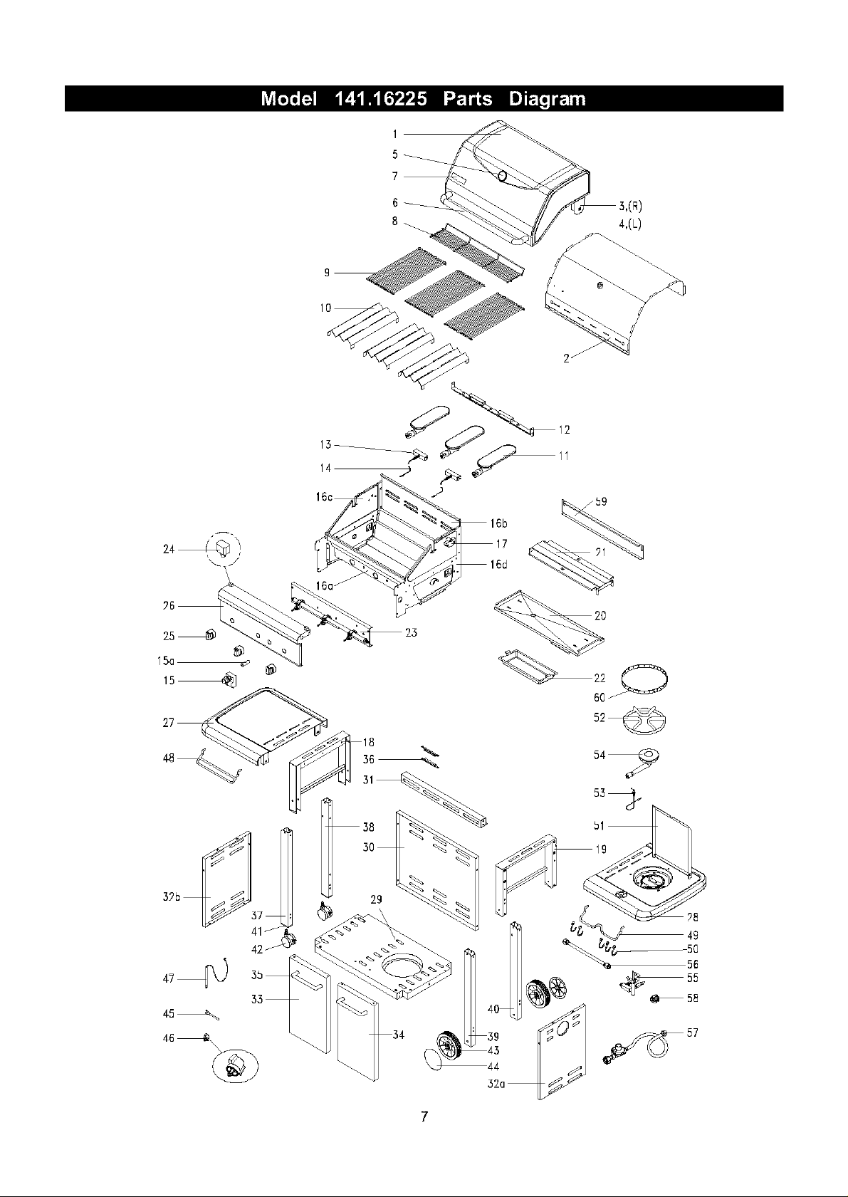
REF# DESCRIPTION
PART#
QTY
1. Lid
2. Lid Trim Plate
3. Lid Hinge Support, Right
4. Lid Hinge Support, Left
5. Temperature Gauge
6. Lid Handle
7. Name Plate
8. Cooking Rack/Secondary
9. Cooking Grid
10. Flame Tamer/Steel
11. Burner/Main
12. Burner Bracket
13. Gas Collector Box with Electrode
14. Electric Wire Set
15. Electric Ignitor, 4-port
15a. Battery/AA
16a. Bowl Panel, Front
16b. Bowl Panel, Rear
16c. Bowl Panel, Left
16d. Bowl Panel, Right
17. Bowl Hinge Support
18. Bowl Support Bracket, Left
19. Bowl Support Bracket, Right
20. Grease Draining Tray
21. Grease Draining Tray Heat Shield
22. Grease Receptacle
23. Gas Valve/Manifold Assembly
24. Protective Pad
25. Control Knob for Main Burner
26. Control Panel
27. Side Shelf
28. Side Burner Frame
29. Cart Bottom Shelf
30. Cart Rear Panel
31. Door Bracket
32a. Cart Side Panel, Right
32b. Cart Side Panel, Left
33. Door, Left
34. Door, Right
35. Door Handle
POO138016A
POO11401JV
P03322001C
P03322002C
P00601174A
P00205006B
P00410037C
P01504001E
P01602001E
P01705002E
P02OOl008C
P02203021B
P02608001A
P02615003A
P02502024C
P05301001A
P0073810GA
P0072509GA
P00720054A
P00721054A
P03321O01D
P01304O04D
P01305004D
P02705015B
P06903005B
P02701075B
Y0060075
P055180031
P03412331C
P02906017B
P01102004C
P01104002C
P01002O04D
P07702015B
P03301O05D
P07606001B
P07605001B
P04302005A
P04303005A
P00203002C
1
1
1
1
1
1
1
1
3
3
3
1
2
1
1
1
1
1
1
1
2
1
1
1
1
1
1
2
3
1
1
1
1
1
1
1
1
1
1
2
8
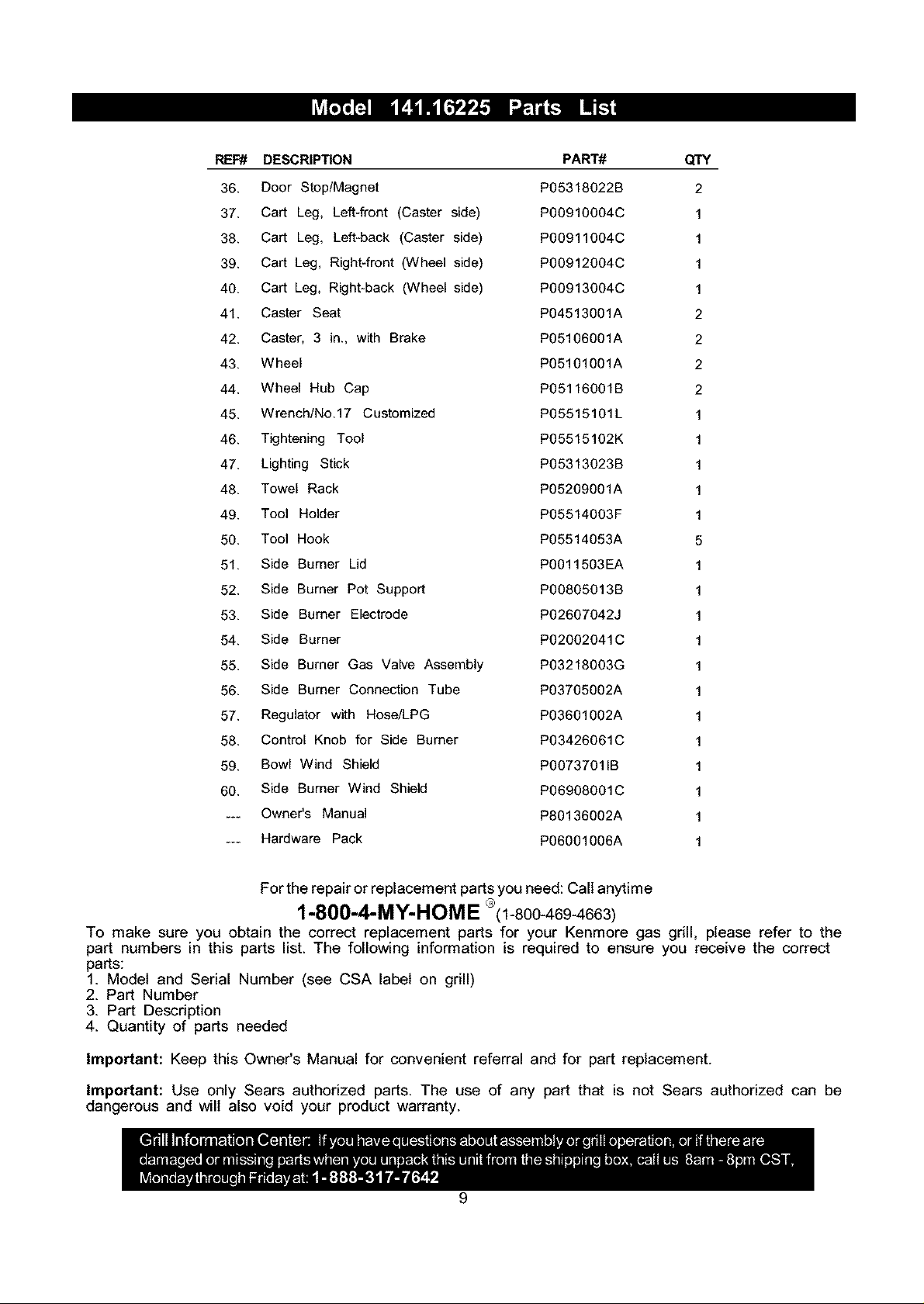
REF# DESCRIPTION PART# QTY
36. Door Stop/Magnet P05318022B 2
37. Cart Leg, Left-front (Caster side) P00910004C 1
38. Cart Leg, Left-back (Caster side) P00911004C 1
39. Cart Leg, Right-front (Wheel side) P00912004C 1
40. Cart Leg, Right-back (Wheel side) P00913004C 1
41. Caster Seat P04513001A 2
42. Caster, 3 in., with Brake P05106001A 2
43. Wheel P05101001A 2
44. Wheel Hub Cap P05116001B 2
45. Wrench/No.17 Customized P05515101L 1
46. Tightening Tool P05515102K 1
47. Lighting Stick P05313023B 1
48. Towel Rack P05209001A 1
49. Tool Holder P05514003F 1
50. Tool Hook P05514053A 5
51. Side Burner Lid P0011503EA 1
52. Side Burner Pot Support P00805013B 1
53. Side Burner Electrode P02607042J 1
54. Side Burner P02002041C 1
55. Side Burner Gas Valve Assembly P03218003G 1
56. Side Burner Connection Tube P03705002A 1
57. Regulator with Hose/LPG P03601002A 1
58. Control Knob for Side Burner P03426061C 1
59. Bowl Wind Shield P00737011B 1
60. Side Burner Wind Shield P06908001C 1
... OwneCs Manual P80136002A 1
... Hardware Pack P06001006A 1
For the repair or replacement parts you need: Call anytime
1-800-4-MY-HOME °(1-800-469-4663)
To make sure you obtain the correct replacement parts for your Kenmore gas grill, please refer to the
part numbers in this parts list. The following information is required to ensure you receive the correct
parts:
1. Model and Serial Number (see CSA label on grill)
2. Part Number
3. Part Description
4. Quantity of parts needed
Important: Keep this Owner's Manual for convenient referral and for part replacement.
Important: Use only Sears authorized parts. The use of any part that is not Sears authorized can be
dangerous and will also void your product warranty.
9
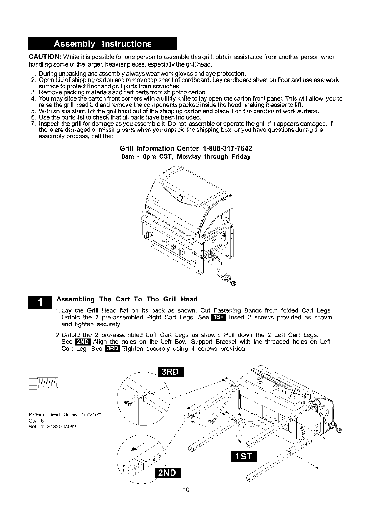
CAUTION: While it is possible for one person to assemble this grill, obtain assistance from another person when
handling some of the larger, heavier pieces, especially the grill head.
1. During unpacking and assembly always wear work gloves and eye protection.
2. Open Lid of shipping carton and remove top sheet of cardboard. Lay cardboard sheet on floor and use as a work
surface to protect floor and grill parts from scratches.
3. Remove packing materials and cart parts from shipping carton.
4. You may slice the carton front corners with a utility knife to lay open the carton front panel. This will allow you to
raise the grill head Lid and remove the components packed inside the head, making it easier to lift.
5. With an assistant, lift the grill head out of the shipping carton and place it on the cardboard work surface.
6. Use the parts list to check that all parts have been included.
7. Inspect the grill for damage as you assemble it. Do not assemble or operate the grill if it appears damaged. If
there are damaged or missing parts when you unpack the shipping box, or you have questions during the
assembly process, call the:
Grill Information Center 1-888-317-7642
8am - 8pm CST, Monday through Friday
m
Pattern Head Screw 1/4"xl/2"
Qty. 6
Ref. # $132G04082
Assembling The Cart To The Grill Head
1. Lay the Grill Head flat on its back as shown. Cut Fastening Bands from folded Cart Legs.
Unfold the 2 pre-assembled Right Cart Legs. See W Insert 2 screws provided as shown
and tighten securely.
2.Unfold the 2 pre-assembled Left Cart Legs as shown. Pull down the 2 Left Cart Legs.
See _ Align the holes on the Left Bowl Support Bracket with the threaded holes on Left
Cart Leg. See I1_ Tighten securely using 4 screws provided.
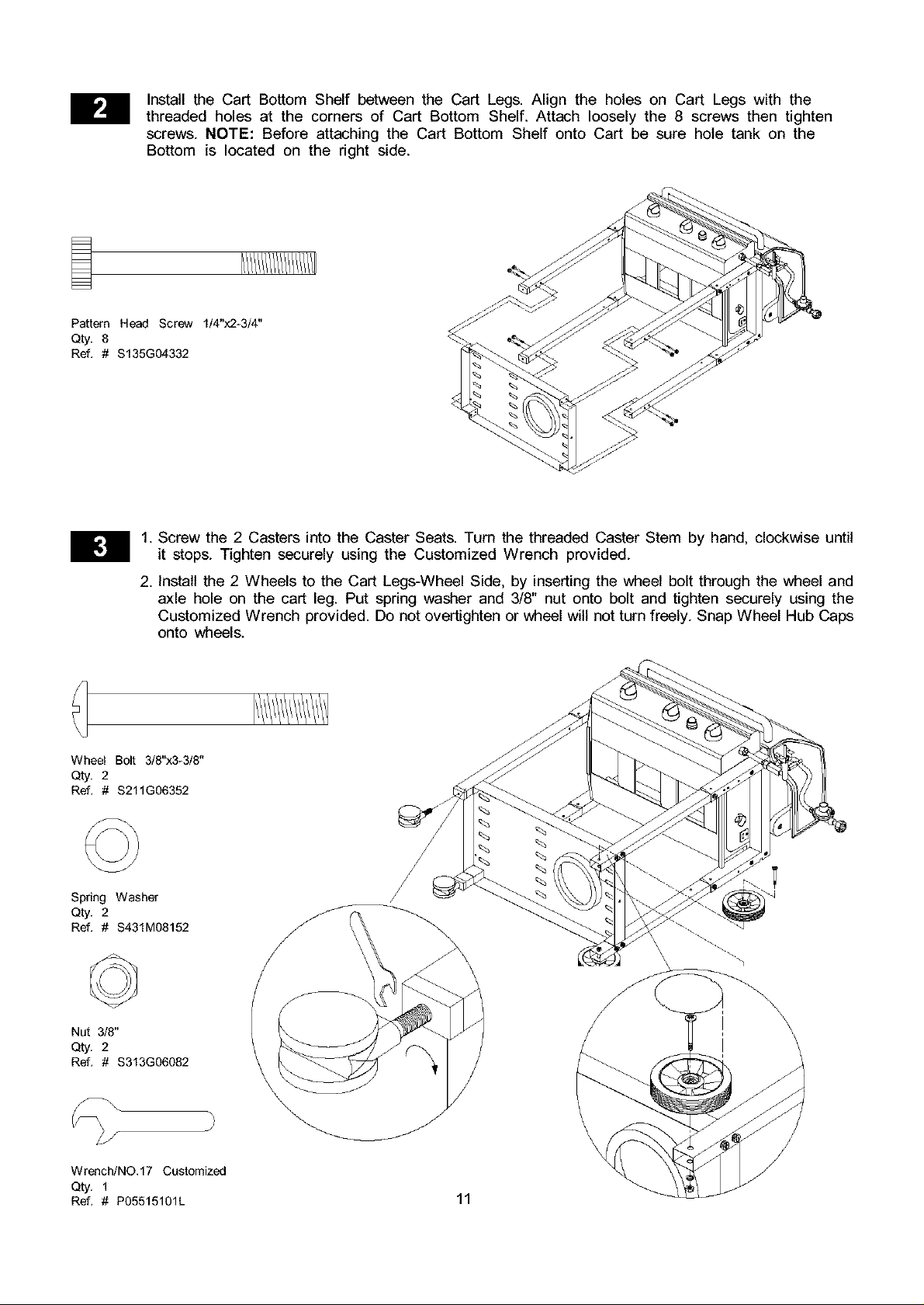
Install the Cart Bottom Shelf between the Cart Legs. Align the holes on Cart Legs with the
threaded holes at the corners of Cart Bottom Shelf. Attach loosely the 8 screws then tighten
screws. NOTE: Before attaching the Cart Bottom Shelf onto Cart be sure hole tank on the
Bottom is located on the right side.
Pattern Head Screw 1/4"x2-3/4"
Qty. 8
Ref. # $135G04332
1. Screw the 2 Casters into the Caster Seats. Turn the threaded Caster Stem by hand, clockwise until
it stops. Tighten securely using the Customized Wrench provided.
2. Install the 2 Wheels to the Cart Legs-Wheel Side, by inserting the wheel bolt through the wheel and
axle hole on the cart leg. Put spring washer and 3/8" nut onto bolt and tighten securely using the
Customized Wrench provided. Do not overtighten or wheel wilt not turn freely. Snap Wheel Hub Caps
onto wheels.
Wheel Bolt 3/8"x3-3/8"
Qty. 2
Ref. # $211G06352
Spring Washer
Qty. 2
Ref. # S431M08152
Nut 3/8"
Qty. 2
Ref. # $313G06082
Wrench/NO.17 Customized
Q_. 1
Ref. # P05515101L 11
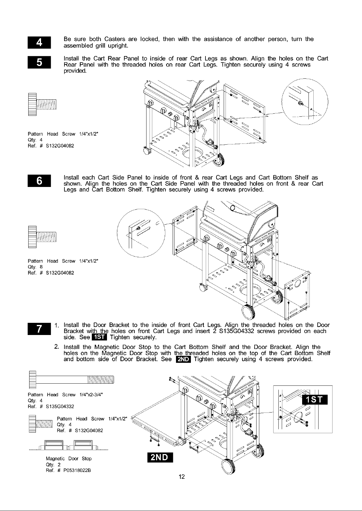
BesurebothCastersare locked,thenwith the assistanceof anotherperson,turnthe
assembledgrillupright.
InstalltheCartRearPanelto insideof rearCartLegsasshown.Alignthe holesontheCart
RearPanelwiththe threadedholeson rearCartLegs.Tightensecurelyusing4 screws
provided.
Pattern Head Screw 1/4"xl/2"
Qty. 4
Ref. # $132G04082
Install each Cart Side Panel to inside of front & rear Cart Legs and Cart Bottom Shelf as
shown. Align the holes on the Cart Side Panel with the threaded holes on front & rear Cart
Legs and Cart Bottom Shelf. Tighten securely using 4 screws provided.
\
/
Pattern Head Screw 1/4"xl/2"
Qty. 8
Ref. # $132G04082
Ill. Install the Door Bracket to the inside of front Cart Legs. Align the threaded holes on the Door
Bracket with the holes on front Cart Legs and insert 2 $135G04332 screws provided on each
side. See E_I Tighten securely.
2. Install the Magnetic Door Stop to the Cart Bottom Shelf and the Door Bracket. Align the
holes on the Magnetic Door Stop with the threaded holes on the top of the Cart Bottom Shelf
and bottom side of Door Bracket. See _ Tighten securely using 4 screws provided.
Pattern Head Screw 1/4"x2-3/4"
Qty. 4
Ref. # $135G04332
Pattern Head Screw 1/4"xl/2"
Qty. 4
Ref. # $132G04082
Magnetic Door Stop
Qty. 2
Ref. # P05318022B
12
 Loading...