

Kenmore 141.157951, 141.157941 Owner's Manual
Owner's Manual
E: L ! T
Liquid Propane Gas Grill
Model141.157941
Natural Gas Grill
Model141.157951
f
TM
IIfllll
Z_ WARNING:
ReadthisOwner'sManualcarefullyandbesure your
gas grillispropedyassembled, installedand main-
tained. Failure to follow these instructionscould
resultinsedous bodilyinjuryand/orpropertydam-
age. This gas gdll is intendedfor outdooruseonly
and isnot intendedto be installedinor on
recreationalvehiclesor boats.
Note to Installer:
Leave thisOwner's Manual withtheconsumer
afterdeliveryand/orinstallation.
O O
m
Note to Consumer:
Leave this Owner'sManual ina convenientplace
for future reference.
Manufacturer Customer Service Helpline:
If the shipping box is missing parts or you have
questions about assembly,call the Customer Ser-
vice Helpline 8am - 11pro CST, Mondaythrough
Fridayat 1-888-317-7642.
Sears, Roebuck and Co.,
Hoffman Estates, IL 60179 U.S.A.
P4775B - Rev: 04/21/00
Warranty ..................................................... 2
Safety Instructions ..................................... 2
Pre-Assembly Instructions ......................... 4
Parts Diagram and Part Lists ............... 5
Assembly Instructions ................................. 8
Lighting Instructions .................................. 14
Cooking Instructions ................................ 16
Cleaning and Maintenance Instructions .... 16
Frequently Asked Questions .................. 19
Cooking Guide and Recipes ................ 20
From the date of purchase for the designated time
periods listed below, Sears will replace the following
grillpartsfree of charge if theyare defectiveinmaterial
or workmanship.
• Lifetime of Grill: Exterior Stainless Steel Parts,
Aluminum Castings (except for paint loss)
/_ WARNING
Failure to comply with these instructions
could result in a fire or explosion which
could cause serious bodily injury, death,
or property damage.
Grill Installation Codes
This gas grill must be installed in accordance
with all local codes. In areas without local
codes, follow the latest edition of the National
Fuel Gas Code ANSI Z223.1. In Canada. installa-
tion must conform to standard CAN/CGA lb149.1
or 1-b149.2 (Installation Code for Gas Burning
Appliances and Equipment) and all local codes.
Proper Placement and Clearance of Grill
Never use your gas grill ina garage, porch,shed,
breezewayor anyotherenclosedarea. Yourgas grill
isto be used outdoors only, at least 24" from the
back and side of any combustible surface.Your
gas grillshould not be placed under any surface
that will bum. Do not obstruct theflow of ventila-
tion air around the gas gdll housing.
This outdoorgas grillis notintendedto be installedin
or on recreational vehicles and/or beats.
• 3 Years: Flame Tamers, Cooking Grids, Burners
• 5 Years: All Other Grill Parts (except ignitorbattery)
This warranty does not cover:
• Labor costs for repairs
• Grill if it is used for commercial or rental
purposes.
Replacement parts are available by contacting the
nearest Sears Service Center.
This warranty applies only when the grill is used
in the United States.
This warranty gives you specific legal rights, and
you may also have other rights which vary from
state to state.
Sears, Roebuck and Co., Dept. 817WA,
Hoffman Estates, IL 60179
Correct LPG Cylinder Use
LPG grill models are designed for use with a
standard 20 lb. Liquid Propane Gas (LPG)
cylinder, not included with grill box. Never
connect your gas grill to an LPG cylinder that
exceeds this capacity. A cylinder of approxi-
mately 12 inches in diameter by 18-1/2 inches
high should be the maximum size LPG cylinder
used. We recommend buying an "OPD" gas
cylinderwhich offers an Overfill Prevention
Device. This safety feature prevents the cylinder
from being overfilledwhich can cause malfunction
of the LPG cylinder, regulator and/or grill.
The LPG cylinder must be constructed and
marked in accordance with specificationsof the
U.S. Dept. of Transportation (DOT). In Canada,
the LPG cylinder must meet the Canadian
Transportationand Communications(CTC)
specifications. Also be sure:
1. The LPG cylinder has a shutoff valve, termi-
nating in an LPG supply cylinder valve outlet,
that is compatible with a Type 1 cylinder
connection device. The LPG cylinder must
also have a safety relief device that has a
direct communication with the vapor space of
the cylinder.
2. The cylinder supply system must be arranged
for vapor withdrawal.
3. The LPG cylinder used must have a collar
to protect the cylinder valve.
2 © Sears, Roebuck and Co.
WARNING
Failure to comply with these instructions
could result in a fire or explosion which
could cause serious bodily injury, death,
or property damage.
• Never connect an unregulated LPG cylinder
to your gas grill. The gas regulator assembly
supplied with your gas grill is adjusted to
have an outlet pressure of 11" water column
(W.C.) for connection to an LPG cylinder.
• Only use the regulator and hose assembly
supplied with your gas grill. Replacement
regulators and hose assemblies must be
those specified by Sears.
• Have your LPG cylinder filled by a reputable
propane gas dealer and visually inspected
and re-qualified at each filling.
• Never fill the gas cylinder beyond 80% full.
Have your propane gas dealer check the
release valve after every filling to ensure that
it remains free of defects.
• Always keep LPG cylinders in an upright
position.
• Do not store (or use) gasoline or other flammable
vapors and liquids in the vicinity of this gas gdll.
• An LPG cylinder that is not connected for use
must not be stored in the vicinityof this or any
other gas grill.
• Do not subject the LPG cylinder to excessive
heat.
• Never store an LPG cylinder indoors. If you
store your gas grill in the garage or other
indoor location, always disconnect the LPG
cylinder first and store it safely outside.
• LPG cylinders must be stored outdoors in a
well-ventilated area. Disconnected LPG cylin-
ders must not be stored in a building,
garage or any other enclosed area.
• When your gas grill is not in use the gas
must be turned off at the LPG cylinder.
• The regulator and hose assembly must be
inspected before each use of the grill. If
there is excessive abrasion or wear or if the
hose is cut, it must be replaced prior to the
grill being used again.
• Keep the gas regulator hose away from
hot grill surfaces and dripping grease.
Avoid unnecessary twisting of hose. Visually
inspect hose prior to each use for cuts,
cracks, excessive wear or other damage.
• If the hose appears damaged do not use gas
grill. Call Sears at 1-800--4-MY-HOME for
a Sears authorized replacement hose.
• Never light your gas grill with the lid closed
or before checking to insure the burner tubes
are fully seated over the gas valve orifices.
• Never allow children to operate your grill. Do
not allow children to play near your grill.
WARNING
IF YOU SMELL GAS:
• Shut off gas supply to the grill.
• Extinguish any open flame.
• Open grill lid.
• If odor continues, immediately call your
gas company or local fire department.
Failure to comply with these instructions
could result in a fire or explosion which
could cause serious bodily injury, death, or
property damage.
WARNING
A strong gas smell, or the hissing sound of
gas indicates a serious problem with your
gas grill or the LPG cylinder. Failure to
immediately follow the steps listed below
could result in a fire or explosion which
could cause serious bodily injury, death, or
propertydamage.
• Get away from the LPG cylinder.
• Do not try to fix the problem yourself.
• Call your fire department. (Do not call
near the LPG cylinder because your
telephone is an electrical device.)
CAUTION: Spiders and small insects occa-
sionally spin webs or make nests in the
grill burner tubes dudng transit and
warehousing. These webs can lead to a gas
flow obstruction which could result in a fire
in and around the burner tubes. This type of
fire is known as a "FLASH-BACK" and can
cause serious damage to your grill and
create an unsafe operating condition for the
user.
Although an obstructed burner tube is not
the only cause of "FLASH-BACK", it is the
most common cause.
To reduce the chance of "FLASH-BACK",
you must clean the burner tubes before
assembling your grill, and at least once a
month in late summer or early fall when
spiders are most active. Also perform this
burner tube cleaning procedure if your gdll
has not been used for an extended period
of time.
3
/h WARNING
Toreduce the chance of "FLASH-BACK" (see
caution on page 3) clean the burner tubes and
burners before fully assembling your grill• Remove
the cotter pin from the rear underside of each
burner using a pair of long nose pliers. Carefully
lift each burner up and away from the gas valve
orifice, then refer to Figure 1 and perform one of
these three cleaning methods:
1. Bend a stiff wire, (a lightweight coat hanger
works well) into a small hook as shown
below• Run the hook through the burner tube
and inside the burner several times to remove
any debris•
( ;- '1)
2. Use a bottle brush with a flexible handle• Run
the brush through the burner tube and inside
the burner several times, removing any debris.
3. Use an air hose to force air through each
burner tube. The forced air should pass debds
or obstructions through the burner and out the
ports.
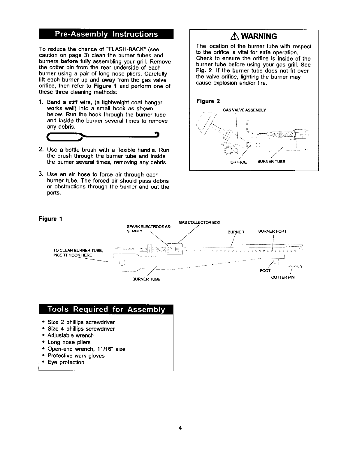
The location of the burner tube with respect
to the orifice is vital for safe operation.
Check to ensure the orifice is inside of the
burner tube before using your gas grill. See
Fig. 2. If the burner tube does not fit over
the valve orifice, lighting the burner may
cause explosion and/or fire.
Figure 2
GAS VALVE ASSEMBLY
ORIFICE BURNER TUBE
Figure 1
TO CLEAN BURNER TUBE,
INSERT HOOK HERE
• Size 2 phillipsscrewdriver
• Size 4 phillips screwdriver
• Adjustable wrench
• Long nose pliers
• Open-end wrench, 11116" size
• Protective work gloves
• Eye protection
SPARK ELECTRODE AS-
SEMBLY "_ _ BURNER BURNER PORT
/
BURNER TUBE COTTER PIN
GAS COLLECTOR BOX
_J
I i
FOOT _
4
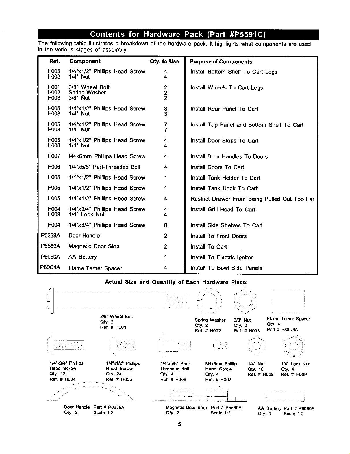
The following table illustrates a breakdown of the hardware pack. It highlights what components are used
in the various stages of assembly.
Ref,
H005
H008
H001
H002
H003
H005
H008
H005
H008
H005
Hog8
HO07
H006
H005
H005
H005
H004
H009
HO04
P0239A
Component Qty. to Use
1/4"xl/2" Phillips Head Screw 4
1/4" Nut 4
3/8" Wheel Bolt 2
Spring Washer 2
3/8" Nut 2
1/4"xl/2" Phillips Head Screw 3
1/4" Nut 3
1/4"xl/2" Phillips Head Screw 7
1/4" Nut 7
1/4"xl/2" Phillips Head Screw 4
1/4" Nut 4
M4x6mm Phillips Head Screw 4
1/4"x5/8" Part-Threaded Bolt 4
1/4"xl/2" Phillips Head Screw 1
1/4"xl/2" Phillips Head Screw 1
1/4"xl/2" Phillips Head Screw 4
1/4"x3/4" Phillips Head Screw 4
1/4" Lock Nut 4
1/4"x3/4" Phillips Head Screw 8
Door Handle 2
Purpose of Components
Install Bottom Shelf To Cart Legs
Install Wheels To Cart Legs
Install Rear Panel To Cart
Install Top Panel and Bottom Shelf To Cart
Install Door Stops To Cart
Install Door Handles To Doors
Install Doors To Cart
Install Tank Holder To Cart
Install Tank Hook To Cart
Restdct Drawer From Being Pulled Out Too Far
Install Grill Head To Cart
Install Side Shelves To Cart
Install To Front Doors
P5589A
P8080A
P80C4A
114"x3/4"Phillips 114"xl/2" Phillips
Head Screw Head Screw
Qty. 12 Qty. 24
Ref. # H004 Ref. # H005
Magnetic Door Stop 2
AA Battery 1
Flame Tamer Spacer 4
Actual Size and Quantity of Each Hardware Piece:
3/8" Wheel Bolt
Qty. 2
Ref. # H001
\
J J ". \\
/ •
Door Handle Part # P0239A
Qty. 2 Scale 1:2
Install To Cart
Install To Electric Ignitor
Install To Bowl Side Panels
Spring Washer 318" Nut Flame Tamer Spacer
Qty. 2 Qty. 2 Qty. 4
r
Ref. # H002 Ref. # H003 Part # PSOC4A
, , ,, ,
1/4"x518" Part- M4x6mm Phillips
Threaded Bolt Head Screw
Qty. 4 Qty. 4
Ref, # H006 Ref. # H007
Magnetic Door Stop Part # P5589A
Qty. 2 Scale 1:2
5
i
1/4" Nut 1/4" Lock Nut
Qty. 18 Qty. 4
Ref. # H0O8 Ref. # H009
AA Battery Part # PS08OA
Qty. 1 Scale 1:2
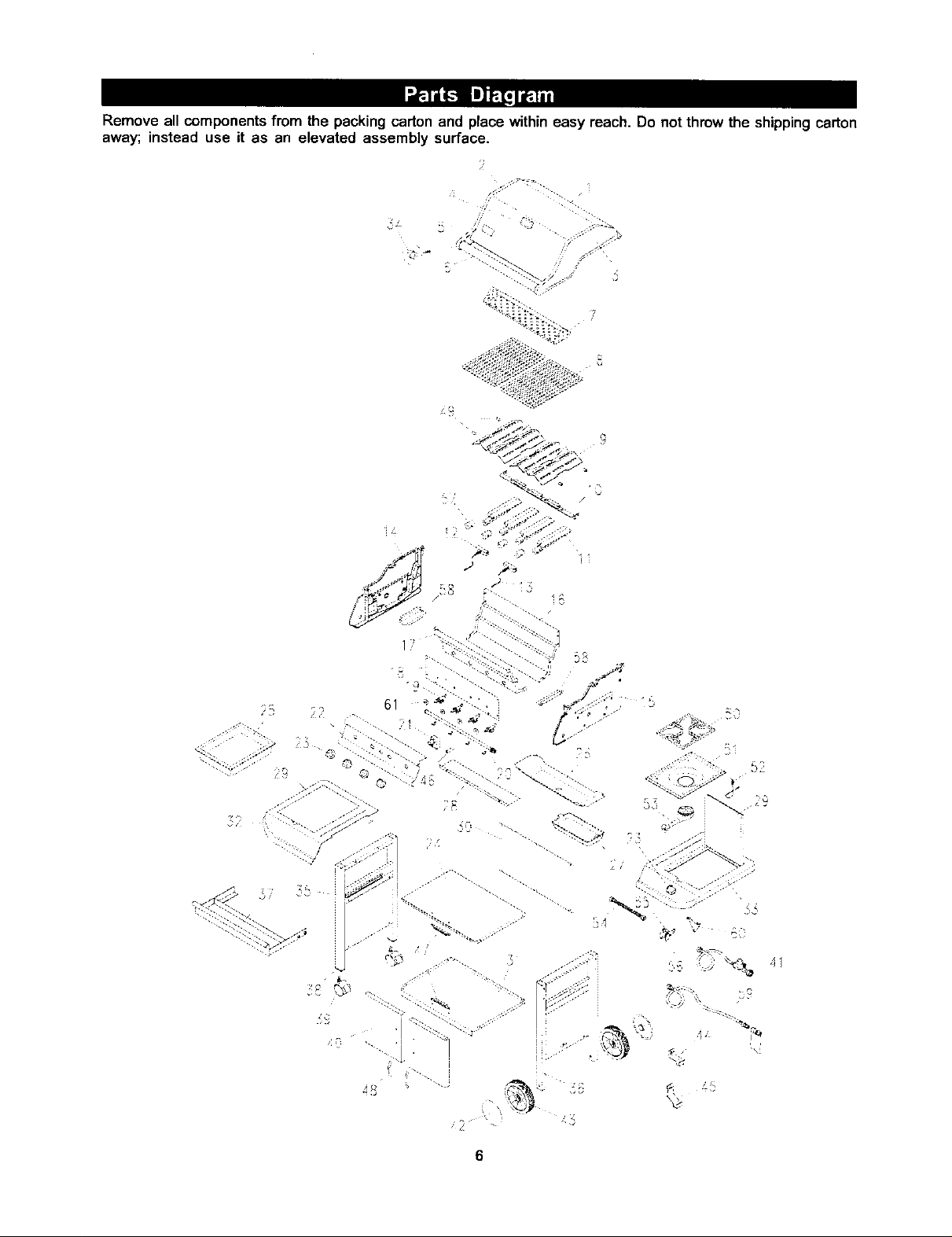
Removeallcomponentsfrom the packing carton and place within easy reach. Do not throw the shipping carton
away; instead use it as an elevated assembly surface.
_ . 7f
= .
?: ! > -N
'I
¢ 7 "_ ,I,
AR
41
6
DESCRIPllON PART# QI"Y RE_# DESCRIPTION
PART# QTY
1. Lid - Stainless Steel P0149F 1
2. Lid Side Panel - Left PO145B 1
3. Lid Side Panel - Right PO144B 1
4. Temperature Gauge P0615B 1
5. Name Plate P0459A 1
6. Lid Handle P0237D 1
7. Swing-Away Warming Rack P1522A 1
8. Cast Iron Cooking Grid P1648B 2
9. Stainless Steel Flame Tamer P1733A 2
10. Burner Support Bracket P2218B 1
11. Burner P1935A 4
12. Gas Collector Box w/ Electrode P2618A 2
13. Ignition Wire Set P2626B 1
14. Bowl Panel - Left P0728D 1
15. Bowl Panel - Right P0727D 1
16. Bowl Panel - Rear P0732B 1
17. Bowl Panel - Front P0731B 1
18. Heat Shield P2942B 1
19. Gas Valve Assembly 4
- L.P.G. P3297C
- N.G. P3297F
20. Gas Manifold P5028A 1
21. Electric Ignitor P2503C 1
22. Control Panel P2942A 1
23. Control Knob P3409B 5
24. Top Panel of Cabinet P1042B 1
25. Storage Bin P1134A 1
26. Grease Draining Tray P2725A 1
27. Grease Receptacle P2717C 1
28. Lower Heat Shield P2944A 1
29. Insert Plate - Stainless Steel P1131B 2
30. Rear Panel P4327A 1
31. Bottom Shelf of Cabinet P1042A 1
32. Side Shelf P1131E 1
33. Side Burner Body P1137B 1
34. Heat-Insulating Spacer P5573A 2
35. Cart Legs - Castor Side P0932A 1
36. Cart Legs - Wheel Side P0832A 1
37. Drawer - Stainless Steel PS078E 1
38. Castor Seat P4521A 2
39. Castor P5109A 2
40. Front Door P4328A 2
41. Regulator and Hose (L.P.G. only) P3632E 1
42. Wheel Hub - Graphite P5113C 2
43. Wheel - Graphite P5106D 2
44. Tank Hook (L.P.G. only) P4029A 1
45. Tank Holder (L.P.G. only) P4029B 1
46. AA Battery P8080A 1
47. Magnetic Door Stop P5589A 2
48. Door Handle P0239A 2
49. Flame Tamer Spacer PSOC4A 4
50. Pot Support P80C6A 1
51. Side Burner Body - Inner P2323B 1
52. Electrode Assembly P2627A 1
53. Burner Assembly P1922A 1
54. Connection Tube P3983E 1
55. Adaptor P3998A 1
56. Gas Valve Assembly 1
- L.P.G. P3298A
- N.G. P3298B
57. Air Shutter (N.G. only) P80C7A 4
58. Grease Shield P80CSA 2
59. N.G. 12' Hose Kit P3718A 1
60. Gas Valve Bracket P80C9A 1
61. Rain Shield P80D5A 4
-- Owner's Manual P4775B 1
-- Hardware Pack (contents page 5) P5591C 1
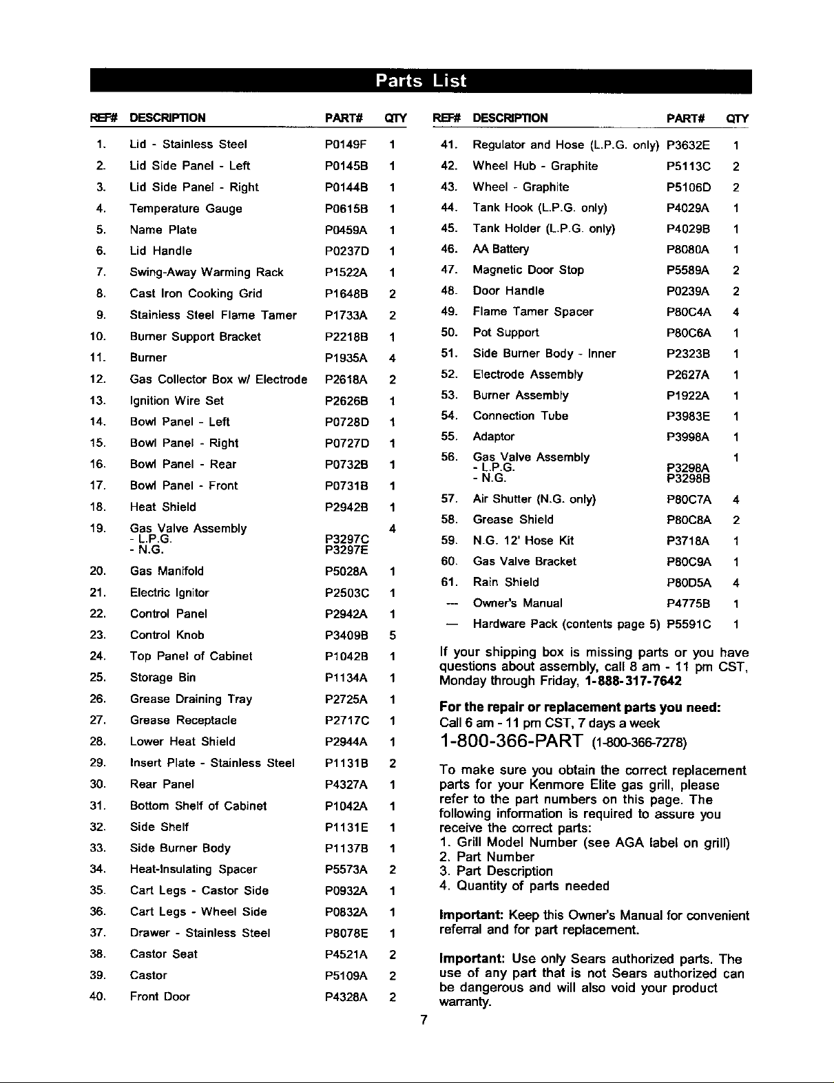
If your shipping box is missing parts or you have
questions about assembly, call 8 am - 11 pm CST,
Monday through Friday, 1-888-317-7642
For the repair or replacement parts you need:
Call 6 am - 11 pm CST, 7 days a week
1-800-366-PART (1-800-366-7278)
To make sure you obtain the correct replacement
parts for your Kenmore Elite gas grill, please
refer to the part numbers on this page. The
following information is required to assure you
receive the correct parts:
1. Grill Model Number (see AGA label on grill)
2. Part Number
3. Part Description
4. Quantity of parts needed
Important: Keep this Owner's Manual for convenient
referral and for part replacement.
Important: Use only Sears authorized parts. The
use of any part that is not Sears authorized can
be dangerous and will also void your product
warranty.
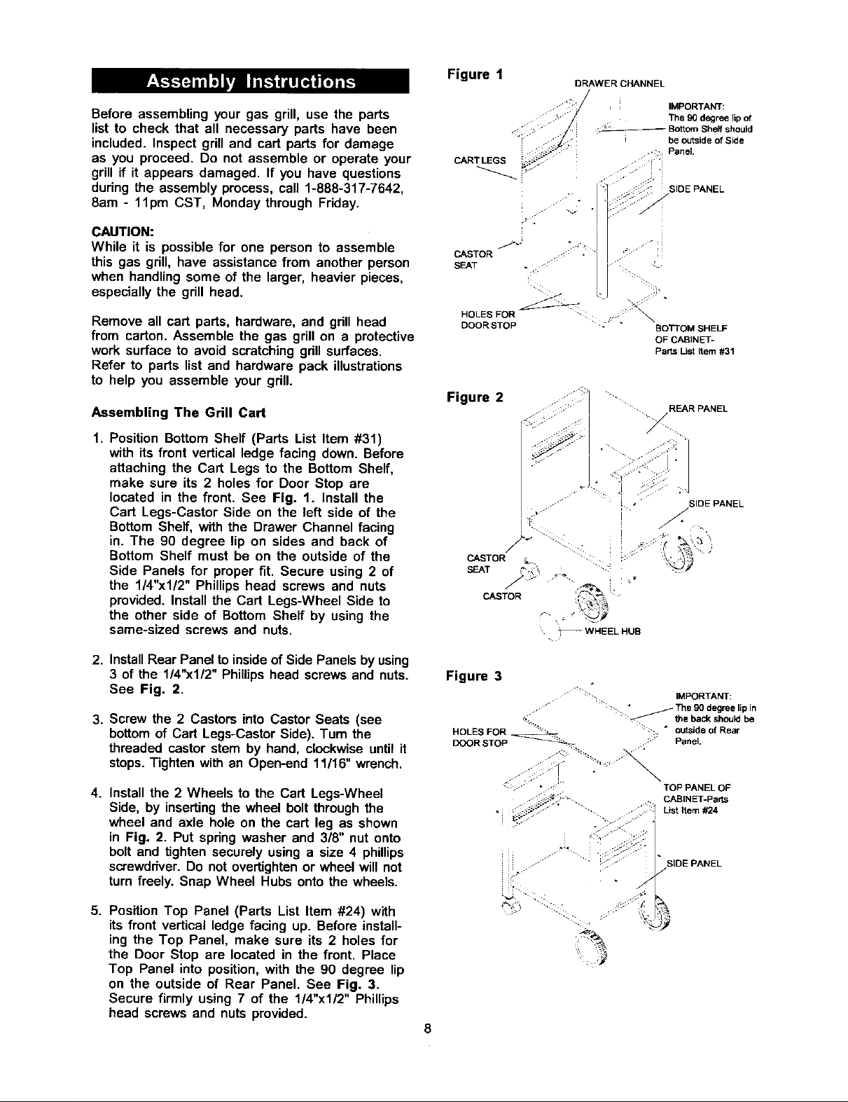
Figure 1
DRAWER CHANNEL
Beforeassemblingyourgas grill, use the parts
list to check that all necessary parts have been
included• Inspect grill and cart parts for damage
as you proceed• Do not assemble or operate your
grill if it appears damaged• If you have questions
during the assembly process, call 1-888-317-7642,
8am - 11pm CST, Monday through Friday•
CAUTION:
While it is possible for one person to assemble
this gas grill, have assistance from another person
when handling some of the larger, heavier pieces,
especially the grill head.
Remove all cart parts, hardware, and grill head
from carton. Assemble the gas grill on a protective
work surface to avoid scratching grill surfaces.
Refer to parts list and hardware pack illustrations
to help you assemble your grill•
Assembling The Grill Cart
1. Position Bottom Shelf (Parts List Item #31)
with its front vertical ledge facing down. Before
attaching the Cart Legs to the Bottom Shelf,
make sure its 2 holes for Door Stop are
located in the front. See Fig. 1. Install the
Cart Legs-Castor Side on the left side of the
Bottom Shelf, with the Drawer Channel facing
in. The 90 degree lip on sides and back of
Bottom Shelf must be on the outside of the
Side Panels for proper fit. Secure using 2 of
the 1/4"x1/2" Phillips head screws and nuts
provided. Install the Cart Legs-Wheel Side to
the other side of Bottom Shelf by using the
same-sized screws and nuts.
- _.:_/ IMPORTANT:
._- The 90 degree lip of
• ./ _ Bottom Sheff should
- _/. i be outside of Side
CART LEGS _:_: i •
CASTOR ::: ,
SEAT • ,: ::
HOLES FOR
DOORSTOP J " BOTTOM SHELF
Figure 2
CASTOR _.. ..: •
SEAT ;-.'
;J; ' Panel.
SIDE PANEL
OF CABINET-
Parts List Item #31
REAR PANEL
' SIDE PANEL
CASTOR
• _WHEELHUB
2. InstallRear Panel to insideof Side Panels by using
3 of the 1/4"x1/2" Phillipshead screws and nuts.
See Fig. 2.
3. Screw the 2 Castors into Castor Seats (see
bottomof Cart Legs-Castor Side). Turn the
threaded castor stem by hand, clockwise until it
stops•Tighten with an Open-end 11/16" wrench.
4. Install the 2 Wheels to the Cart Legs-Wheel
Side, by inserting the wheel bolt through the
wheel and axle hole on the cart leg as shown
in Fig. 2. Put spring washer and 3/8" nut onto
bolt and tighten securely using a size 4 phillips
screwddver. Do not overtightan or wheel will not
turn freely. Snap Wheel Hubs onto the wheels•
5. Position Top Panel (Parts List Item #24) with
its front vertical ledge facing up. Before install-
ing the Top Panel, make sure its 2 holes for
the Door Stop are located in the front• Place
Top Panel into position, with the 90 degree lip
on the outside of Rear Panel. See Fig. 3.
Secure firmly using 7 of the 1/4"x1/2" Phillips
head screws and nuts provided•
Figure 3
IMPORTANT:
... " :" :-:. _ The 90 degree lip in
HOLES FOR < _..... :': " o_uesiLde(_ofheOUa_be
DOOR STOP _ ;'" Panel.
TOP PANEL OF
: ;:-" . . . CABINET-Parts
_;_-. . , List Item #24
-" SIDE PANEL
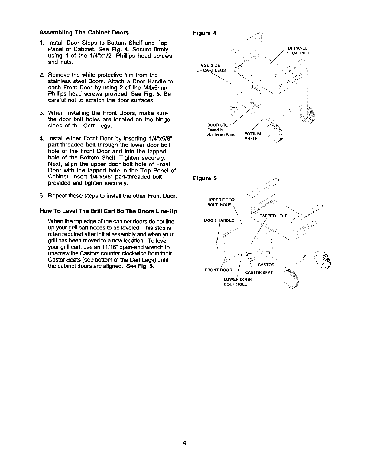
Assembling The Cabinet Doors
1. Install Door Stops to Bottom Shelf and Top
Panel of Cabinet. See Fig. 4. Secure firmly
using 4 of the 1/4"x1/2" Phillips head screws
and nuts.
2. Remove the white protective film from the
stainless steel Doors. Attach a Door Handle to
each Front Door by using 2 of the M4x6mm
Phillips head screws provided. See Fig. 5. Be
careful not to scratch the door surfaces.
3. When installingthe Front Doors, make sure
the door bolt holes are located on the hinge
sides of the Cart Legs.
4. Install either Front Door by inserting 1/4"x5/8"
part-threaded bolt through the lower door bolt
hole of the Front Door and into the tapped
hole of the Bottom Shelf. Tighten securely.
Next, align the upper door bolt hole of Front
Door with the tapped hole in the Top Panel of
Cabinet. Insert 1/4"x5/8" part-threaded bolt
provided and tighten securely.
Figure 4
DOOR STO D
Found in
Figure 5
.,.J..
f
TOP PANEL
• OF CABINET
/
/
SHELF
5. Repeat these stepsto installthe other Front Door.
How To Level The Grill Cart So The Doors Line-Up
When the top edge of the cabinetdoorsdo not line-
up yourgdllcart needsto be leveled. Thisstep is
oftenrequiredafterinitialassemblyandwhenyour
grillhas been movedtoa newlocation. To level
yourgrillcart,usean 11/16"open-endwrenchto
unscrewthe Castorscounter-clockwisefrom their
CastorSeats (see bottomofthe Cart Legs) until
the cabinet doorsare aligned. See Fig. 5.
UPPER DOOR
ZL\
TAPPED HOLE
,- j,
.':_ >
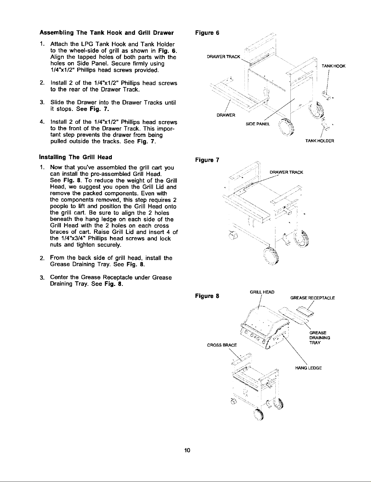
Assembling The Tank Hook and Grill Drawer
1.
Attach the LPG Tank Hook and Tank Holder
to the wheel-side of grill as shown in Fig. 6.
Align the tapped holes of both parts with the
holes on Side Panel. Secure firmly using
1/4"xl/2" Phillips head screws provided.
2. Install 2 of the 1/4"x1/2" Phillips head screws
to the rear of the Drawer Track.
3. Slide the Drawer into the Drawer Tracks until
it stops. See Fig. 7.
4.
Install 2 of the 1/4"x1/2" Phillips head screws
to the front of the Drawer Track. This impor-
tant step prevents the drawer from being
pulled outside the tracks. See Fig. 7.
Figure 6
DRAWER TRACK
TANK HOOK
DRAWER
SIDE PANEL
TANK HOLDER
Installing The Grill Head
1.
Now that you've assembled the grill cart you
can install the pre-assembled Grill Head.
See Fig. 8. To reduce the weight of the Grill
Head, we suggest you open the Grill Lid and
remove the packed components. Even with
the components removed, this step requires 2
people to lift and position the Grill Head onto
the grill cart. Be sure to align the 2 holes
beneath the hang ledge on each side of the
Grill Head with the 2 holes on each cross
braces of cart. Raise Grill Lid and insert 4 of
the 1/4"x3/4" Phillips head screws and lock
nuts and tighten securely.
2. From the back side of grill head, install the
Grease Draining Tray. See Fig. 8.
3. Center the Grease Receptacle under Grease
Draining Tray. See Fig. 8.
Figure 7
Figure 8
CROSS BRACE
DRAWER TRACK
.... •••,
GRILL HEAD
GREASE RECEPTACLE
GREASE
DRAINING
TRAY
10
HANG LEDGE
 Loading...