

Kenmore 141.153371, 141.173371 Owner's Manual
Owner's Manual
Liquid Propane Gas Grill
Model141.153371
Natural Gas Grill
Model141.173371
WARNING:
Read this Owner's Manual carefully and be sure
your gas grill is properly assembled, installed and
maintained. Failure to follow these instructions
could result in serious bodily injury and/or property
damage. This gas grill is intended for outdoor use
only and is not intended to be installed in or on
recreational vehicles or boats.
Note to Installer: Leave this Owner's Manual
with the consumer after delivery and/or installa-
tion.
Note to Consumer: Leave this Owner's
Manual in a convenient place for future reference.
Sears, Roebuck and Co.,
Hoffman Estates, IL 60179 U.S.A.
P80106054A - Date: 2003/11/04
Warranty ..................................................... 2
Safety Instructions .................................... 2
Hardware ..................................................... 6
Parts Diagram and Lists ..................... 10
Assembly Instructions ............................. 13
Lighting Instructions ................................. 24
Cleaning and Maintenance Instructions...27
Frequently Asked Questions ................ 29
Cooking Instructions ............................. A-1
Cooking Guide and Recipes ............. A-2
Full 1-Year Warranty on Grill
For one year from the date of purchase Sears
will repair or replace, at our option, any grill part
(except for paint loss, rusting and ignitor battery)
that is defective in material or workmanship.
Limited Warranty on Selected Grill Parts
From one year after the date of purchase for the
designated time periods listed below, Sears will
replace the following grill parts if they are defec-
tive in material or workmanship. You will be
charged for labor.
• Lifetime of Grill: Aluminum Castings (except for
paint loss)
• 1 Year: Cast Iron Burners
• 2 Years: All Other Grill Parts (except flame tamers,
cooking grids and ignitor battery)
Warranty Service
Warranty service is available by contacting the
nearest Sears Service Center at 1-800-4-MY-
HOME @
Warranty Restrictions
• This warranty is void if grill is used for com-
mercial or rental purposes.
• This warranty applies only when the grill is
used in the United States.
• This warranty gives you specific legal rights,
and you may also have other rights which vary
from state to state.
Sears, Roebuck and Co., Dept. 817WA,
Hoffman Estates, IL60179
/_kWARN ING
Combustion byproducts produced when using
this product contain chemicals known to the
State of California to cause cancer, birth
defects, or other reproductive harm.
/_WARNING
Failure to comply with these instructions
could result in a fire or explosion that
could cause serious bodily injury, death, or
property damage.
Z_WARNING
Your grill will get very hot. Never lean over
the cooking area while using your grill. Do not
touch cooking surfaces, grill housing, Lid or any
other grill parts while the grill is in operation, or
until the grill has cooled down after use.
Failure to comply with these instructions
may result in serious bodily injury.
Z_WARNING
(a) Do not store a spare LP-gas cylinder
under or near this appliance;
(b) Never fill the cylinder beyond 80 percent
full; and
(c) If the information in "(a)" and "(b)" is not
followed exactly, a fire causing death or
serious injury may occur.
FOR YOUR SAFETY
1. Do not store or use gasoline or other flam-
mable material and liquids in the vicinity of this
or any other appliance.
2. ALP cylinder not connected for use must not
be stored in the vicinity of this or any other
appliance.
FOR YOUR SAFETY
If you smell gas:
1.Shut off gas to the appliance.
2. Extinguish any open flame such as candle,
cigarette, lighter, etc., that could cause gas to
ignite.
3. Open the Grill Lid.
4. If odor continues, immediately call your gas
supplier or your fire department.
IMPORTANT: Your Kenmore LP Gas Grill cannot
be converted to use Natural Gas. Attempting to do
so is extremely hazardous and will also void the
grill warranty.
Grill Installation Codes
The installation must conform with local codes or, in
the absence of local codes, with either the National
Fuel Gas Code, ANSI Z223.1/NFPA 54, or CAN/
CGA-B149.1, Natural Gas and Propane Installation
Code.
2
© Sears, Roebuck and Co.
Correct LP Gas Tank Use
LP gas grill models are designed for use with a
standard 20 lb. Liquid Propane Gas (LP gas) tank,
not included in grill box. Never connect your gas
grill to an LP gas tank that exceeds this capacity. A
tank of approximately 12 inches in diameter by
18-1/2 inches high is the maximum size LP gas
tank to use. You must use an "OPD" gas tank
which offers a listed Overfill Prevention Device.
This safety feature prevents tank from being over-
filled which can cause malfunction of LP gas tank,
regulator and/or gdtl.
The LP gas tank must be constructed and marked
in accordance with the Specifications for LP-Gas
Cylinders of the U.S. Department of Transportation
(D.O.T.) or the National Standard of Canada, CAN/
CSA-B339, Cylinders, Spheres and Tubes for Trans-
portation of Dangerous Goods; and Commission, as
applicable.
1. The LP gas tank has a shutoff valve, termi-
nating in an LP gas supply tank valve outlet,
that is compatible with a Type 1 tank con-
nection device. The LP gas tank must also
have a safety relief device that has a direct
connection with the vapor space of the tank.
2. The tank supply system must be arranged
for vapor withdrawal.
3. The LP gas tank used must have a collar
to protect the tank valve.
Proper Placement and Clearance of Grill
Never use your gas grill in a garage, porch, shed,
breezeway or any other enclosed area. Your gas grill is
to be used outdoors only, at least 24 inches from the
back and side of any combustible surface. Do not
locate this appliance under overhead unprotected
combustible surfaces. Do not obstruct theflow of
ventilation air around the gasgrill housing.
This outdoor gas grill is not intended to be installed in
or on recreational vehicles and/or boats.
• Never connect an unregulated LP gas tank to
your gas grill. The gas regulator assembly
supplied with your gas grill is adjusted to have
an outlet pressure of 11" water column (W.C.)
for connection to an LP gas tank.
• Only use the regulator and hose assembly
supplied with your gas grill. Replacement
regulators and hose assemblies must be those
specified by Sears.
• Have your LP gas tank filled by a reputable
propane gas dealer and visually inspected and
re-qualified at each filling.
• Never fill the gas tank beyond 80% full.
Have your propane gas dealer check the
release valve after every filling to ensure that
it remains free of defects.
• Always keep LP gas tanks in upright position.
Do not store (or use) gasoline or other flammable
vapors and liquids in the vicinity of this gas grill.
• LP gas tanks not connected for use must NOT be
stored on bottom shelf or in the vicinity of this or
any other gas grill.
• Do not subject the LP gas tank to excessive heat.
• Never store an LP gas tank indoors. If you
store your gas grill in the garage or other
indoor location, always disconnect the LP gas
tank first and store it safely outside.
• LP gas tanks must be stored outdoors in a
well-ventilated area and out of the reach of
children. Disconnected LP gas tanks must not
be stored in a building, garage or any other
enclosed area.
• When your gas grill is not in use the gas
must be turned off at the LP gas tank.
• The regulator and hose assembly can be seen
after opening the doors (if applicable), must be
inspected before each use of the grill. If there
is excessive abrasion or wear or if the hose is
cut, it must be replaced prior to the grill being
used again.
• Keep the gas regulator hose away from hot
grill surfaces and dripping grease. Avoid unnec-
essary twisting of hose. Visually inspect hose
prior to each use for cuts, cracks, excessive
wear or other damage. If the hose appears
damaged do not use the gas grill. Call Sears
at 1-800-4-MY-HOME (1-800-469-4663) for a
Sears authorized replacement hose.
• Never light your gas grill with the lid closed or
before checking to ensure the burner tubes are
fully seated over the gas valve orifices.
• Never allow children to operate your grill. Do
not allow children to play near your grill.
Z WARNING
If you smell gas:
• Shut off gas supply to the gas grill.
• Turn the Control Knobs to OFF position.
• Extinguish any open flame such as candle,
cigarette, lighter, etc., that could cause gas
to ignite.
• Open the Grill Lid.
• Get away from the LP gas tank.
• Do not try to fix the problem yourself.
• If odor continues or you have a fire you
cannot extinguish, call your fire depart-
ment. Do not call near the LP gas tank
because your telephone is an electrical
device and could create a spark resulting
in fire and/or explosion.
NOTE: The normal flow of gas through the
regulator and hose assembly can create a
humming noise. A low volume of noise is
perfectly normal and will not interfere with
operation of the grill. If humming noise is
loud and excessive you may need to purge
air from the gas line or reset the regulator
excess gas flow device. This purging proce-
dure should be done every time a new LP
gas tank is connected to your grill. For help
call the Grill Information Center for assis-
tance, 8am - 8pm CST, Monday through
Friday 1-888-317-7642.
3
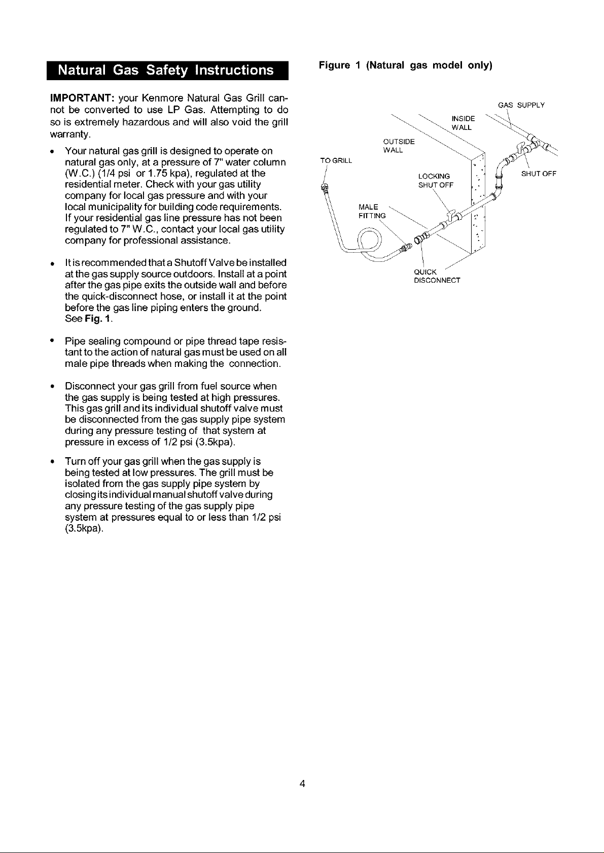
Figure 1 (Natural gas model only)
IMPORTANT: your Kenmore Natural Gas Grill can-
not be converted to use LP Gas. Attempting to do
so is extremely hazardous and will also void the grill
warranty.
Your natural gas grill is designed to operate on
natural gas only, at a pressure of 7" water column
(W.C.) (1/4 psi or 1.75 kpa), regulated at the
residential meter. Check with your gas utility
company for local gas pressure and with your
local municipality for building code requirements.
If your residential gas line pressure has not been
regulated to 7" W.C., contact your local gas utility
company for professional assistance.
It is recommended that a Shutoff Valve be installed
at the gas supply source outdoors. Install at a point
after the gas pipe exits the outside wall and before
the quick-disconnect hose, or install it at the point
before the gas line piping enters the ground.
See Fig. 1.
• Pipe sealing compound or pipe thread tape resis-
tant to the action of natural gas must be used on all
male pipe threads when making the connection.
Disconnect your gas grill from fuel source when
the gas supply is being tested at high pressures.
This gas grill and its individual shutoff valve must
be disconnected from the gas supply pipe system
during any pressure testing of that system at
pressure in excess of 1/2 psi (3.5kpa).
TO GRILL
MALE
FITTING
OUTSIDE
WALL
LOCKING
SHUT OFF
\
\
\
\
\
QUICK
DISCONNECT
GAS SUPPLY
INS_OE
WALL
SHUTOFF
Turn off your gas grill when the gas supply is
being tested at low pressures. The grill must be
isolated from the gas supply pipe system by
closing its individual manual shutoff valve during
any pressure testing of the gas supply pipe
system at pressures equal to or less than 1/2 psi
(3.5kpa).
4
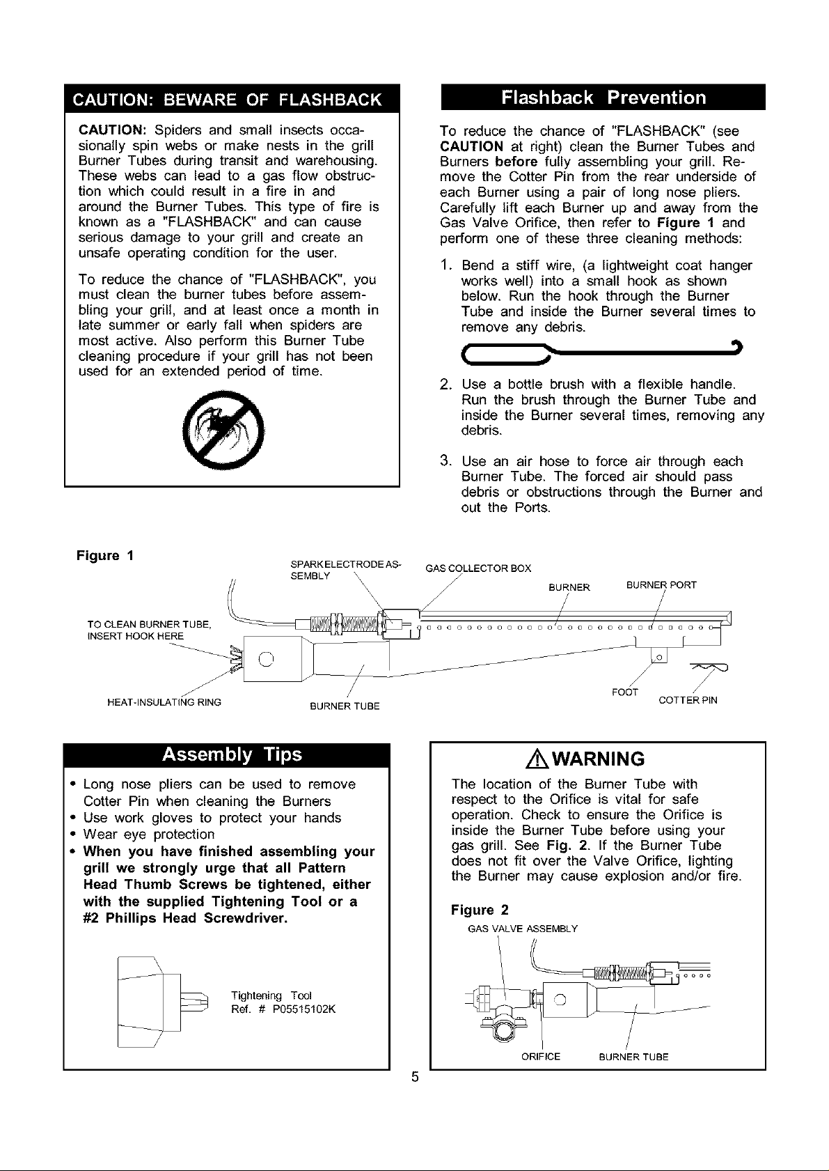
CAUTION:Spidersandsmallinsectsocca-
sionallyspinwebsor makenestsin thegrill
BurnerTubesduringtransitandwarehousing.
Thesewebscanleadto a gasflow obstruc-
tionwhichcouldresultin a fire in and
aroundthe BurnerTubes.Thistypeof fire is
knownas a "FLASHBACK"andcancause
seriousdamageto yourgrillandcreatean
unsafeoperatingconditionfor the user.
To reducethe chanceof "FLASHBACK",you
mustcleantheburnertubesbeforeassem-
blingyourgrill,andat leastoncea monthin
late summeror earlyfall whenspidersare
mostactive.Alsoperformthis BurnerTube
cleaningprocedureif yourgrill hasnotbeen
usedfor an extendedperiodof time.
To reducethe chanceof "FLASHBACK"(see
CAUTIONat right)cleanthe BurnerTubesand
Burnersbeforefully assemblingyourgrill.Re-
movethe CotterPinfromtherearundersideof
eachBurnerusinga pairof longnosepliers.
Carefullylift eachBurnerupandawayfromthe
GasValveOrifice,thenreferto Figure 1 and
perform one of these three cleaning methods:
.
Bend a stiff wire, (a lightweight coat hanger
works well) into a small hook as shown
below. Run the hook through the Burner
Tube and inside the Burner several times to
remove any debris.
( J
. Use a bottle brush with a flexible handle.
Run the brush through the Burner Tube and
inside the Burner several times, removing any
debris.
.
Use an air hose to force air through each
Burner Tube. The forced air should pass
debris or obstructions through the Burner and
out the Ports.
.. ')
Fiurea 1 SPARK ELECTRODE AS- GAS COLLECTOR BOX
HEAT-INSULATING RING BURNER TUBE COTTER PiN
SEMBLY \ /
o o o o o o o o o o o o o o D U _ U U a 0 0
FOOT /
/ WARNING
• Long nose pliers can be used to remove
Cotter Pin when cleaning the Burners
• Use work gloves to protect your hands
• Wear eye protection
• When you have finished assembling your
grill we strongly urge that all Pattern
Head Thumb Screws be tightened, either
with the supplied Tightening Tool or a
#2 Phillips Head Screwdriver.
The location of the Burner Tube with
respect to the Orifice is vital for safe
operation. Check to ensure the Orifice is
inside the Burner Tube before using your
gas grill. See Fig. 2. If the Burner Tube
does not fit over the Valve Orifice, lighting
the Burner may cause explosion and/or fire.
Figure 2
GAS VALVE ASSEMBLY
Tightening Tool
Ref. # P05515102K
ORIFICE BURNER TUBE
5
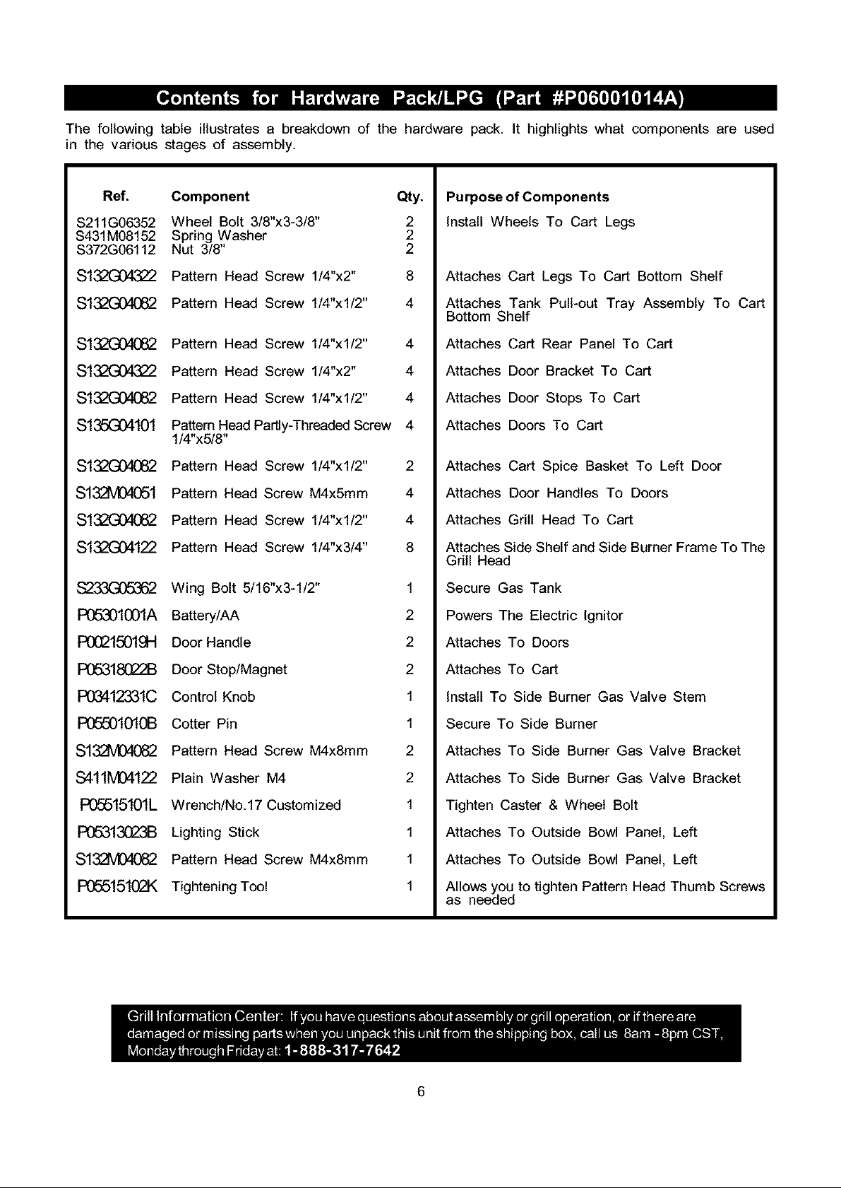
The following table illustrates a breakdown of the hardware pack. It highlights what components are used
in the various stages of assembly.
Ref. Component
S211G06352
S431M08152
S372G06112
$132G04322
$132G04082
$132G04082
S132G043Z2
$132G04082
$135G04101
$132G04082
$132VD4051
$132G04082
$132G04122
S233G0&362
Wheel Bolt 3/8"x3-3/8"
Spring Washer
Nut 3/8"
Pattern Head Screw 1/4"x2"
Pattern Head Screw 1/4"xl/2"
Pattern Head Screw 1/4"xl/2" 4
Pattern Head Screw 1/4"x2" 4
Pattern Head Screw 1/4"xl/2" 4
Pattem Head Partly-Threaded Screw 4
1/4"x5/8"
Pattern Head Screw 1/4"xl/2" 2
Pattern Head Screw M4x5mm 4
Pattern Head Screw 1/4"xl/2" 4
Pattern Head Screw 1/4"x3/4" 8
Wing Bolt 5/16"x3-1/2" 1
Qty.
2
2
2
8
4
Purpose of Components
Install Wheels To Cart Legs
Attaches Cart Legs To Cart Bottom Shelf
Attaches Tank Pull-out Tray Assembly To Cart
Bottom Shelf
Attaches Cart Rear Panel To Cart
Attaches Door Bracket To Cart
Attaches Door Stops To Cart
Attaches Doors To Cart
Attaches Cart Spice Basket To Left Door
Attaches Door Handles To Doors
Attaches Grill Head To Cart
Attaches Side Shelf and Side Burner Frame To The
Grill Head
Secure Gas Tank
P05301001A
POQ215019H
R]&318G22B
P03412331C
P05501010B
$132VD4082
$411M04122
P05515101L
R]5313C_3B
$132VD4082
P05515102K
Battery/AA 2
Door Handle 2
Door Stop/Magnet 2
Control Knob 1
Cotter Pin 1
Pattern Head Screw M4x8mm 2
Plain Washer M4 2
Wrench/No.17 Customized 1
Lighting Stick 1
Pattern Head Screw M4x8mm 1
Tightening Tool 1
Powers The Electric Ignitor
Attaches To Doors
Attaches To Cart
Install To Side Burner Gas Valve Stem
Secure To Side Burner
Attaches To Side Burner Gas Valve Bracket
Attaches To Side Burner Gas Valve Bracket
Tighten Caster & Wheel Bolt
Attaches To Outside Bowl Panel, Left
Attaches To Outside Bowl Panel, Left
Allows you to tighten Pattern Head Thumb Screws
as needed
6
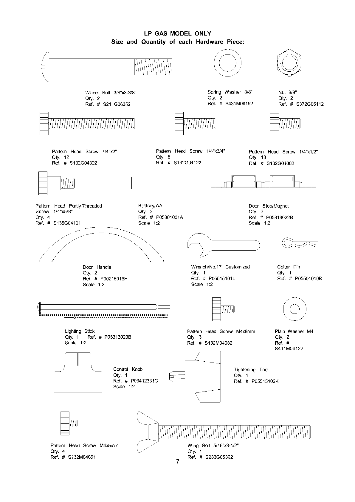
LP GAS MODEL ONLY
Size and Quantity of each Hardware Piece:
Wheel Bolt 3/8"x3-3/8"
Qty. 2
Ref. # $211G06352
Pattern Heed Screw 1/4"x2"
Qty. 12
Ref. # $132G04322
Pattern Heed Partly*Threeded Battery/AA
Screw 1/4"x5/8" Qty. 2
Qty. 4 Ref, # P05301001A
Ref. # $135G04101 Scale 1:2
Pattern Head Screw 1/4"x3/4"
Qty. 8
Ref. # S132G04122
Spring Washer 3/8"
Qty. 2
Ref. # $431M08152
Nut 3/8"
Qty. 2
Ref. # S372G06112
Pattern Heed Screw 1/4"x1/2"
Qty. 18
Ref. # $132G04082
Door Stop/Magnet
Qty. 2
Ref. # P05318022B
Scale 1:2
Door Handle
Qty. 2
Ref, # P00215019H
Scale 1:2
Lighting Stick
Qty. 1 Ref. # P05313023B
Scale 1:2
Control Knob
Qty. 1
Ref. # P03412331C
Scale 1:2
Wrench/No.17 Customized
Qty. 1
Ref. # P05515101L
Scale 1:2
Pattern Heed Screw M4x8mm
Qty. 3
Ref. # $132M04082
Tightening Tool
Qty. 1
Ref. # P05515102K
J
Cotter Pin
Qty. 1
Ref. # P05501010B
Plain Washer M4
Qty, 2
Ref, #
S411M04122
Pattern Heed Screw M4x5mm
Qty. 4
Ref. # $132M04051
Wing Bolt 5/16"x3-1/2"
Qty. 1
Ref. # S233G05362
7
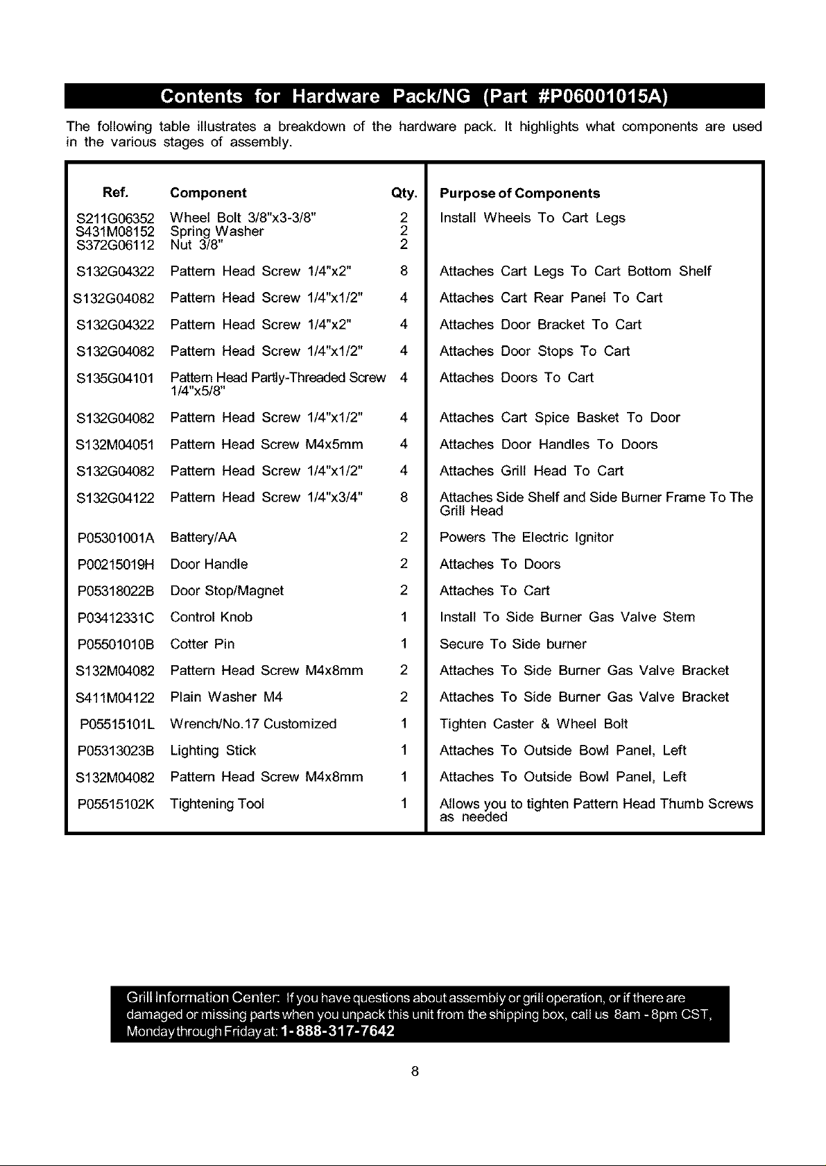
Thefollowingtableillustratesa breakdownof thehardwarepack.It highlights what components are used
in the various stages of assembly.
Ref.
S211G06352
S431MO8152
S372GO6112
S132G04322
S132G04082
S132G04322
S132G04082
S135G04101
S132G04082
S132M04051
S132G04082
S132G04122
P05301001A
P00215019H
P05318022B
P03412331C
Component Qty.
Wheel Bolt 3/8"x3-3/8" 2
Spring Washer 2
Nut 3/8" 2
Pattern Head Screw 1/4"x2" 8
Pattern Head Screw 1/4"x1/2" 4
Pattern Head Screw 1/4"x2" 4
Pattern Head Screw 1/4"x1/2" 4
Pattern Head ParUy-Threaded Screw 4
1/4"x5/8"
Pattern Head Screw 1/4"xl/2" 4
Pattern Head Screw M4x5mm 4
Pattern Head Screw 1/4"xl/2" 4
Pattern Head Screw 1/4"x3/4" 8
Battery/AA 2
Door Handle 2
Door Stop/Magnet 2
Control Knob 1
Purpose of Components
Install Wheels To Cart Legs
Attaches Cart Legs To Cart Bottom Shelf
Attaches Cart Rear Panel To Cart
Attaches Door Bracket To Cart
Attaches Door Stops To Cart
Attaches Doors To Cart
Attaches Cart Spice Basket To Door
Attaches Door Handles To Doors
Attaches Grill Head To Cart
Attaches Side Shelf and Side Burner Frame To The
Grill Head
Powers The Electric Ignitor
Attaches To Doors
Attaches To Cart
Install To Side Burner Gas Valve Stem
P05501010B
S132M04082
S411M04122
PO5515101L
P05313023B
S132M04082
PO5515102K
Cotter Pin 1
Pattern Head Screw M4x8mm 2
Plain Washer M4 2
Wrench/No. 17 Customized 1
Lighting Stick 1
Pattern Head Screw M4x8mm 1
Tightening Tool 1
Secure To Side burner
Attaches To Side Burner Gas Valve Bracket
Attaches To Side Burner Gas Valve Bracket
Tighten Caster & Wheel Bolt
Attaches To Outside Bowl Panel, Left
Attaches To Outside Bowl Panel, Left
Allows you to tighten Pattern Head Thumb Screws
as needed
8
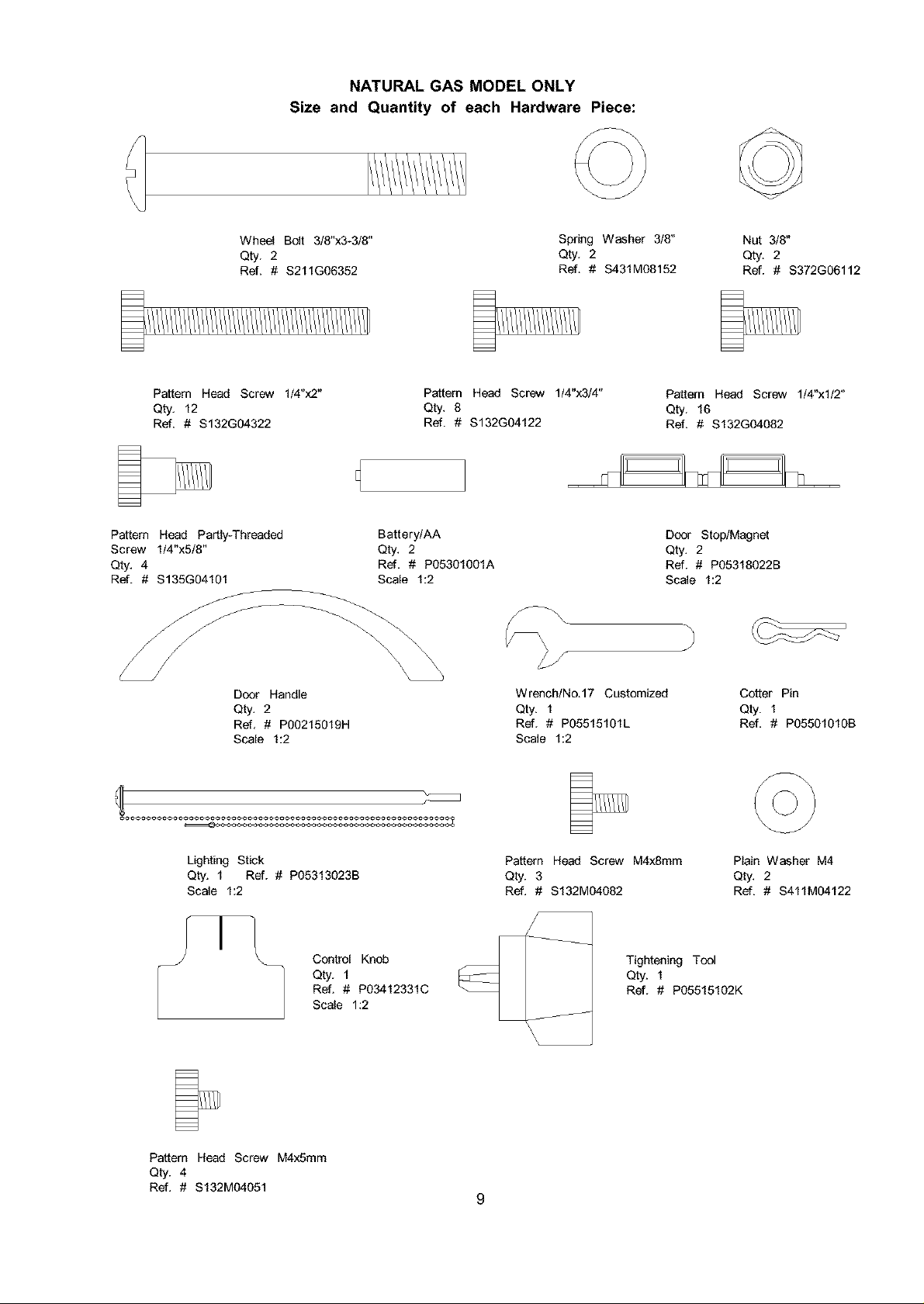
NATURAL GAS MODEL ONLY
Size and Quantity of each Hardware Piece:
Wheel Bolt 3/8"x3-3/8"
Qty. 2
Ref. # $211G06352
Pattern Heed Screw 1/4"x2"
Qty. 12
Ref. # $132G04322
Pattern Heed Partly*Threeded
Screw 1/4"x5/8"
Qty. 4
Ref. # $135G04101
Pattern Head Screw 1/4"x3/4"
Qty. 8
Ref. # $132G04122
Battery/AA
Qty. 2
Ref, # P05301001A
Scale 1:2
Spring Washer 3/8"
Qty. 2
Ref. # $431M08152
Nut 3/8"
Qty. 2
Ref. # $372G06112
Pattern Heed Screw 1/4"x1/2"
Qty. 16
Ref. # $132G04082
Door Stop/Magnet
Qty. 2
Ref. # P05318022B
Scale 1:2
Door Handle
Qty. 2
Ref, # P00215019H
Scale 1:2
Lighting Stick
Qty. 1 Ref. # P05313023B
Scale 1:2
Control Knob
Qty. 1
Ref. # P03412331C
Scale 1:2
Wrench/No.17 Customized
Qty. 1
Ref. # P05515101L
Scale 1:2
Pattern Heed Screw M4x8mm
Qty. 3
Ref. # $132M04082
Tightening Tool
Qty. 1
Ref. # P05515102K
Cotter Pin
Qty. 1
Ref. # P05501010B
Plain Washer M4
Qty, 2
Ref. # S411M04122
Pattern Heed Screw M4x5mm
Qty. 4
Ref. # $132M04051
9
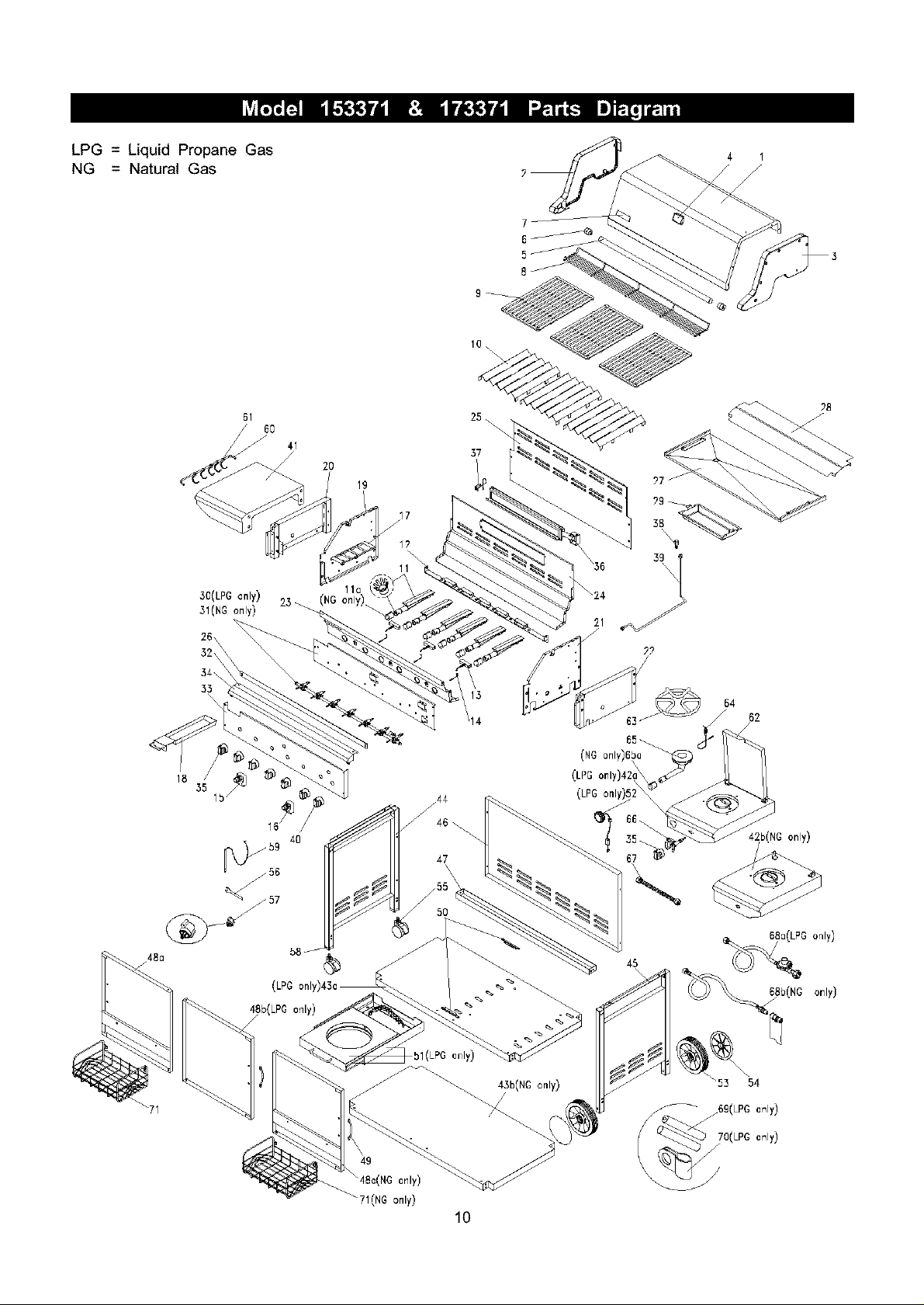
LPG = Liquid Propane Gas
NG = Natural Gas
61
6O
41
30(LPG only) 25 _(NG only)_
31(NG only)
26\
32\
._4\
33
18
55
lb /
_59 40
56
2O
19
11a (
25.
37
17
/
17
_24
\36 39[
2?
54
14
62
(LPGonly
b(NG only)
67
_71
58_
48b(LPG only)
bl(LPG only)
__ 43b(NC only)
49
only)
_71(NG only)
10
Io(LPGonly)
45
\
j668b(NG only)
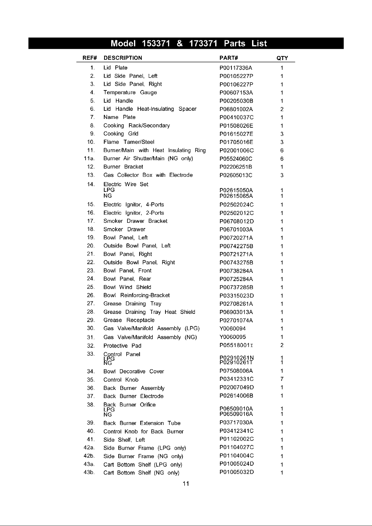
REF# DESCRIPTION
1. Lid Plate
2. Lid Side Panel, Left
3. Lid Side Panel, Right
4. Temperature Gauge
5. Lid Handle
6. Lid Handle Heat-Insulating Spacer
7. Name Plate
8. Cooking Rack/Secondary
9. Cooking Grid
10. Flame TamedSteel
11. Burner/Main with Heat Insulating Ring
11a. Burner Air ShuttedMain (NG only)
12. Burner Bracket
13. Gas Collector Box with Electrode
14. Electric Wire Set
LPG
NG
15. Electric Ignitor, 4-Ports
16. Electric Ignitor, 2-Ports
17. Smoker Drawer Bracket
18. Smoker Drawer
19. Bowl Panel, Left
20. Outside Bowl Panel, Left
21. Bowl Panel, Right
22. Outside Bowl Panel, Right
23. Bowl Panel, Front
24. Bowl Panel, Rear
25. Bowl Wind Shield
26. Bowl Reinforcing-Bracket
27. Grease Draining Tray
28. Grease Draining Tray Heat Shield
29. Grease Receptacle
30. Gas Valve/Manifold Assembly (LPG)
31. Gas Valve/Manifold Assembly (NG)
32. Protective Pad
33. Control Panel
LPG
NG
34. Bowl Decorative Cover
35. Control Knob
36. Back Burner Assembly
37. Back Burner Electrode
38. Back Burner Orifice
LPG
NG
39. Back Burner Extension Tube
40. Control Knob for Back Burner
41. Side Shelf, Left
42a. Side Burner Frame (LPG only)
42b. Side Burner Frame (NG only)
43a. Cart Bottom Shelf (LPG only)
43b. Cart Bottom Shelf (NG only)
11
PART#
P00117336A
P00105227P
P00106227P
P00607153A
P00205030B
P06801002A
P00410037C
P01508026E
P01615027E
P01705016E
P02001006C
P05524060C
P02206251B
P02605013C
P02615050A
P02615065A
P02502024C
P02502012C
P06708012D
P06701003A
P00720271A
P00742275B
P00721271A
P00743275B
P00738284A
P00725284A
P00737285B
P03315023D
P02708261A
P06903013A
P02701074A
Y0060094
Y0060095
P05518001I
P02910261N
P02910261T
P07508006A
P03412331C
P02007049D
P02614006B
P06509010A
P06509016A
P03717030A
P03412341C
P01102002C
P01104027C
P01104004C
P01005024D
P01005032D
QTY
1
1
1
1
1
2
1
1
3
3
6
6
1
3
1
1
1
1
1
1
1
1
1
1
1
1
1
1
1
1
1
1
1
2
1
1
1
7
1
1
1
1
1
1
1
1
1
1
1
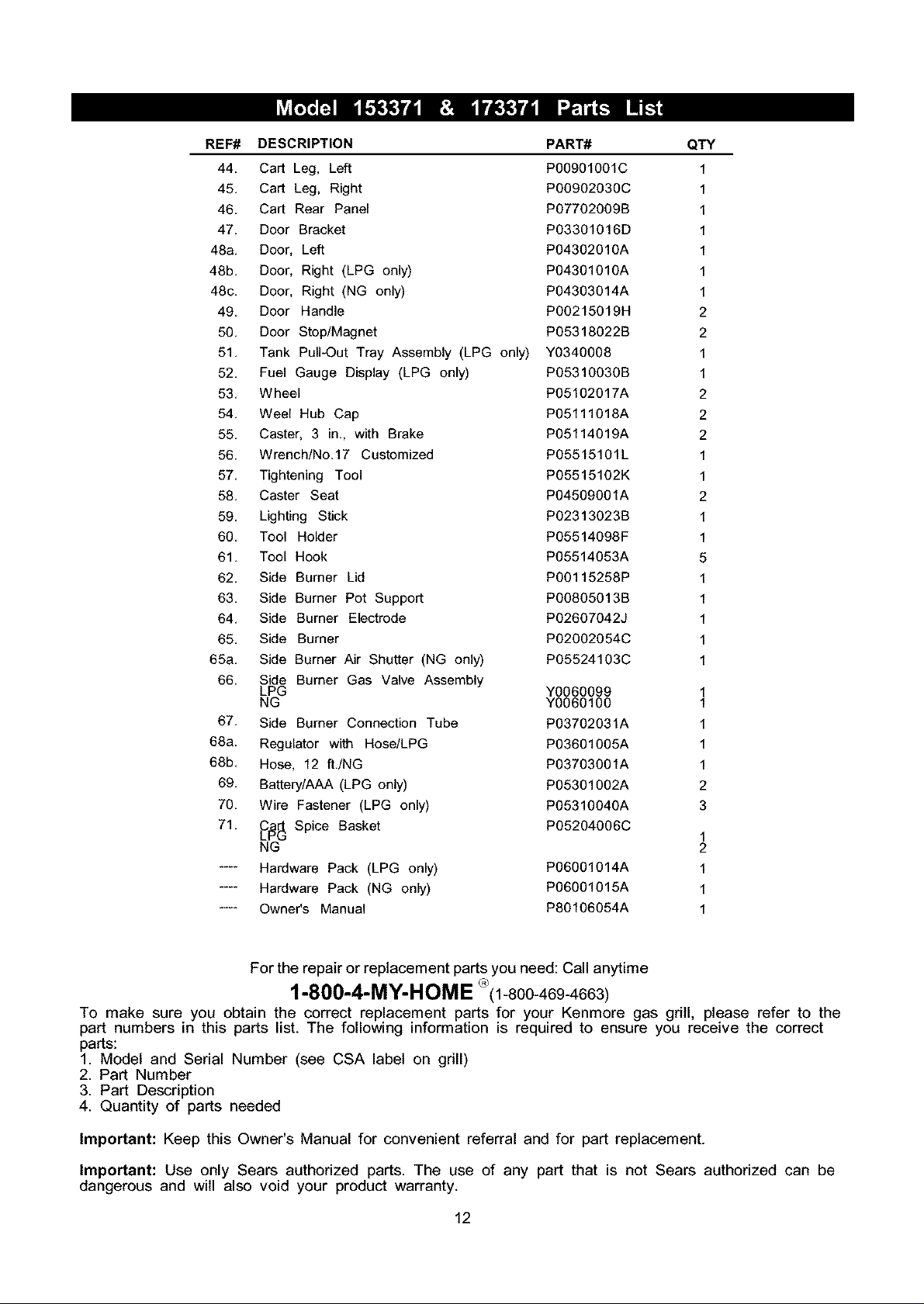
REF# DESCRIPTION PART#
44, Cart Leg, Left P00901001C
45, Cart Leg, Right P00902030C
46, Cart Rear Panel PO7702009B
47, Door Bracket PO3301016D
48a, Door, Left P04302010A
48b, Door, Right (LPG only) P04301010A
48c, Door, Right (NG only) P04303014A
49, Door Handle PO0215019H
50, Door Stop/Magnet PO5318022B
51, Tank Pull-Out Tray Assembly (LPG only) Y0340008
52, Fuel Gauge Display (LPG only) PO531O030B
53, Wheel P05102017A
54, Weel Hub Cap P05111018A
55, Caster, 3 in,, with Brake P05114019A
56, Wrench/No,17 Customized PO5515101L
57, Tightening Tool PO5515102K
58, Caster Seat P04509001A
59, Lighting Stick PO2313023B
60, Tool Holder PO5514098F
61, Tool Hook P05514053A
62, Side Burner Lid PO0115258P
63, Side Burner Pot Support PO0805013B
64, Side Burner Electrode PO2607042J
65, Side Burner P02002054C
65a, Side Burner Air Shutter (NG only) P05524103C
66, Side Burner Gas Valve Assembly
LPG Y0060099
NG Y0060100
67, Side Burner Connection Tube P03702031A
68a, Regulator with Hose/LPG P03601005A
68b, Hose, 12 ft,/NG P03703001A
69, Battery/AAA (LPG only) P05301002A
70, Wire Fastener (LPG only) P0531004OA
71, jC_ Spice Basket P05204006C
NG
.... Hardware Pack (LPG only) P06O01014A
.... Hardware Pack (NG only) P06O01015A
.... Owner's Manual P80106054A
QTY
2
2
2
2
2
2
5
2
3
2
1
1
1
1
1
1
1
1
1
1
1
1
1
1
1
1
1
1
1
1
1
1
1
1
1
1
1
For the repair or replacement parts you need: Call anytime
1-800-4-MY-HOME °(1-800-469-4663)
To make sure you obtain the correct replacement parts for your Kenmere gas grill, please refer to the
part numbers in this parts list. The following information is required to ensure you receive the correct
parts:
1. Model and Serial Number (see CSA label on grill)
2. Part Number
3. Part Description
4. Quantity of parts needed
Important: Keep this Owner's Manual for convenient referral and for part replacement.
Important: Use only Sears authorized parts. The use of any part that is not Sears authorized can be
dangerous and will also void your product warranty.
12
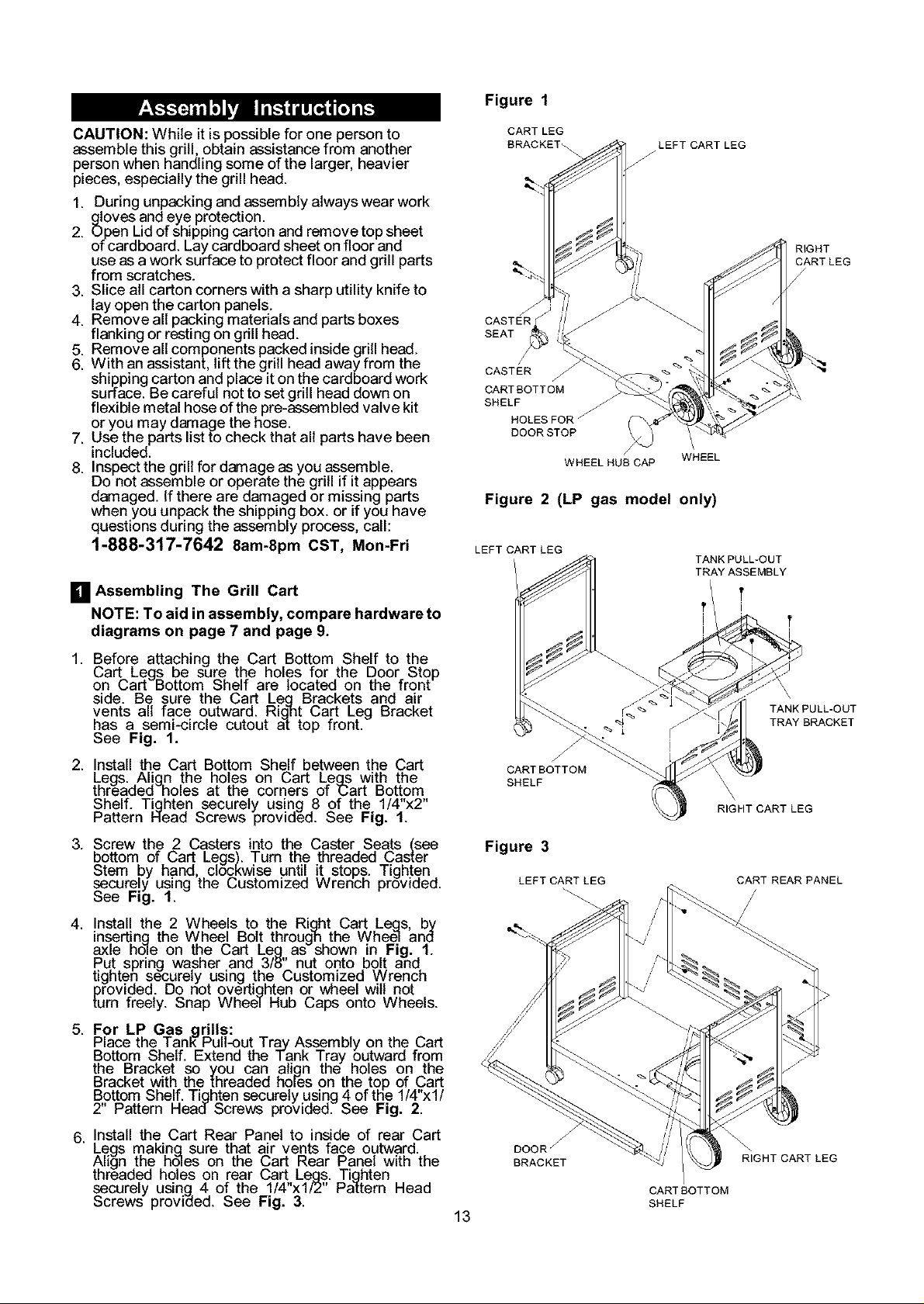
Figure 1
CAUTION:Whileitispossibleforonepersonto
assemble this grill, obtain assistance from another
person when handling some of the larger, heavier
pieces, especially the grill head.
1. During unpacking and assembly always wear work
gloves and eye protection.
2. Open Lid of shipping carton and remove top sheet
of cardboard. Lay cardboard sheet on floor and
use as a work surface to protect floor and grill parts
from scratches.
3. Slice all carton corners with a sharp utility knife to
lay open the carton panels.
4. Remove all packing materials and parts boxes
flanking or resting on grill head.
5. Remove all components packed inside grill head.
6. With an assistant, lift the grill head away from the
shipping carton and place it on the cardboard work
surface. Be careful not to set grill head down on
flexible metal hose of the pre-assemblad valve kit
or you may damage the hose.
7. Use the parts list to check that all parts have been
included.
8. Inspect the grill for damage as you assemble.
Do not assemble or operate the grill if it appears
damaged. If there are damaged or missing parts
when you unpack the shipping box. or if you have
questions during the assembly process, call:
1-888-317-7642 8am-8pm CST, Mon-Fri
[] Assembling The Grill Cart
NOTE: To aid in assembly, compare hardware to
diagrams on page 7 and page 9.
1. Before attaching the Cart Bottom Shelf to the
L,art Legs be sure t.he holes TOrthe DooroStop
on L,art Bottom SheeTare _ocatea on the Tront
side. Be sure the Cart Leg Brackets and air
vents all face outward. Right Cart Leg Bracket
has a semi-circle cutout at top front.
See Fig. 1.
2. Install the Cart Bottom Shelf between the Cart
Legs. Align ,the holes on Cart Leas with the
threaaed hoes at the corners of "Cart Bottom
Shelf. T!ghten securely using 8 of the 1/4"x2"
Pattern Nead Screws provided. See Fig. 1.
3. Screw the 2 Casters into the Caster Seats (sea
bottom of Cart Legs). Turn the threaded Caster
Stem .by hand, ClOCKWiseuntil it stops. Tighten
securely using the L,ustomized Wrencn proviaed.
See Fig. 1.
4. Install the 2 Wheels to the Right Cart Le.qs by
insert!ng the Whe_ Bolt throug]_,the Whee7 and
axle no_e on the L,art Leg as snown in _-ig. 1.
Put spring washer and 3/8" nut onto bolt and,
tighten securely using the L,ustomized Wrench
provided. Do not overti.qhten or wheel wilt not
turn freely. Snap Wheel Hub Caps onto Wheels.
5. For LP Gas _qrills:
Place the Tan_Pull-out Tray Assembly on the Cart
Bottom S.helf. Extend the lank Tray .outward from
the _racKet so you can a_iqn the no_es on the
Bracket with the threaded hoFeson the top of Cart
Bottom Shelf. Tighten securely using 4 of the 1/4"xl/
2" Pattern Head Screws provided. See Fig. 2.
6. Install the Cart Rear Panel to inside of rear Cart
Legs making, sure that air vents face outward.
Align the holes on the Cart Rear Panel with the
threaded holes on rear L,art Legs. Tighten
securely using 4 of the 1/4"xl/2" Pattern Head
Screws provided. See Fig. 3.
CART LEG
BRACKET_
/
CASTER
SEAT
CASTER
CARTBOTTOM
SHELF
HOLES FOR /
DOOR STOP
/
WHEEL HUB CAP WHEEL
Figure 2 (LP gas model only)
LEFT CART LEG
CARTBOTTOM
SHELF
Figure 3
LEFT CART LEG
DOOR /
BRACKET
13
LEFT CART LEG
f
CARTBOTTOM
SHELF
TRAY ASSEMBLY
t i
! t
i i
TANK PULL-OUT
RIGHT CART LEG
CART REAR PANEL
RIGHT CART LEG
RIGHT
CARTLEG
/
TANK PULL-OUT
TRAY BRACKET
 Loading...