

Kenmore 141.152271, 141.17227 Owner's Manual
Owner's Manual
Liquid Propane Gas Grill
Model141.15227.1
Natural Gas Grill
Model 141.17227
Z_ WARNING:
Read this Owner's Manual carefully and be sure
your gas grill is properly assembled, installed and
maintained. Failure to follow these instructions
could result in serious bodily injury and/or property
damage. This gas grill is intended for outdoor use
only and is not intended to be installed in or on
recreational vehicles or boats.
Note to Installer: Leave this Owner's Manual
with the consumer after delivery and/or installation.
Note to Consumer: Leave this Owner's Manual
in a convenient place for future reference.
Sears, Roebuck and Co.,
Hoffman Estates, IL 60179 U.S.A.
P80103070A-Rev:2003/02/19
Warranty ..................................................... 2
Safety Instructions ..................................... 2
Pre-Assembly Instructions ......................... 4
Hardware, Parts Diagram and Lists ..... 6
Assembly Instructions ............................... 10
Lighting Instructions .................................. 17
Cleaningand Maintenance Instructions .... 19
Frequently Asked Questions .................. 21
Cooking Instructions ................................ 22
Z_WARNING
Combustion byproducts produced when using
this product contain chemicals known to the
State of California to cause cancer, birth
defects, or other reproductive harm.
Z_ WARNING
Failure to comply with these instructions
could result in a fire or explosion that
could cause serious bodily injury, death, or
property damage.
Cooking Guide and Recipes ................ 23
Full 1-Year Warranty on Grill
For one year from the date of purchase Sears will
repair or replace, at our option, any grill part
(except for paint loss, rusting and ignitor battery)
that is defective in material or workmanship.
Limited Warranty on Selected Grill Parts
From one year after the date of purchase for the
designated time periods listed below, Sears will
replace the following grill parts if they are defective
in material or workmanship. You will be charged
for labor.
• Lifetime of Grill: Aluminum Castings (except for paint
loss)
• 1 Year: Cast Iron Burners
• 2 Years: All Other Grill Parts (except flame tamers,
cooking grids and ignitor battery)
Warranty Service
Warranty service is available by contacting the
nearest Sears Service Center at 1-800-4-MY-HOME
(¢
Warranty Restrictions
• This warranty is void if grill is used for commer-
cial or rental purposes.
• This warranty applies only when the grill is
used in the United States.
• This warranty gives you specific legal rights,
and you may also have other rights which vary
from state to state.
Sears, Roebuck and Co., Dept. 817WA,
Hoffman Estates, IL 60179
Z_ WARNING
Your grill will get very hot. Never lean over
the cooking area while using your grill. Do not
touch cooking surfaces, grill housing, Lid or any
other grill parts while the grill is in operation, or
until the grill has cooled down after use.
Failure to comply with these instructions
may result in serious bodily injury.
FOR YOUR SAFETY
1. Do not store or use gasoline or other flam-
mable material and liquids in the vicinity of this
or any other appliance.
2. ALP cylinder not connected for use must not
be stored in the vicinity of this or any other
appliance.
FOR YOUR SAFETY
If you smell gas:
1. Shut off gas to the appliance.
2. Extinguish any open flame.
3. Open Lid.
4. If odor continues, immediately call your gas
supplier or your fire department.
Grill Installation Codes
This gas grill must be installed in accordance with
all local codes. In areas without local codes, follow
the latest edition of the National Fuel Gas Code
ANSI Z223.1. and National Electrical Code ANSI/
NFPA 70 In Canada, installation must conform to
standard CAN/CGA lb149.1 or 1-b149.2 (Installation
Code for Gas Burning Appliances and Equipment)
and all local codes.
Correct LP Gas Tank Use
LP gas grill models are designed for use with a
standard 20 lb. Liquid Propane Gas (LP gas) tank,
not included with grill box. Never connect your gas
grill to an LP gas tank that exceeds this capacity.
A tank of approximately 12 inches in diameter by
2 © Sears, Roebuck and Co.
18-1/2incheshighisthemaximumsizeLPgas
tanktouse.Youmust usean "OPD"gastank
whichoffersanOverfill PreventionDevice.
Thissafetyfeaturepreventsthetankfrombeing
overfilledwhichcancausemalfunctionoftheLP
gastank,regulatorand/orgrill.
TheLPgastankmustbeconstructedand
markedinaccordancewithspecificationsof theU.
S. Dept.ofTransportation(DOT).tnCanada,the
LPgastankmustmeettheCanadianTransporta-
tionandCommunications(CTC)specifications.Also
besureto readandfollowall LPinstructions
below.
1. TheLPgastankhasa shutoffvalve,termi-
natingin an LPgassupplytankvalveoutlet,
that is compatiblewitha Type1tankcon-
nectiondevice.TheLP gastankmustalso
havea safetyreliefdevicethathasa direct
connectionwiththe vaporspaceof thetank.
2. Thetanksupplysystemmustbearranged
forvaporwithdrawal.
3. TheLPgas tankusedmusthavea collar
to protectthetankvalve.
Proper Placementand Clearance of Grill
Never use your gas grill in a garage, porch, shed,
breezeway or any other enclosed area. Your gas grill is
to be used outdoors only, at least 24 inches from the
back and side of any combustible surface. Your
gas grill should not be placed under any surface
that will burn. Do not obstruct the flow of ventilation
air around the gas grill housing.
This outdoor gas grill is not intended to be installed in
or on recreational vehicles and/or boats.
• Never connect an unregulated LP gas tank to
your gas grill. The gas regulator assembly
supplied with your gas grill is adjusted to have
an outlet pressure of 11" water column (W.C.)
for connection to an LP gas tank.
• Only use the regulator and hose assembly
supplied with your gas grill. Replacement
regulators and hose assemblies must be those
specified by Sears.
• Have your LP gas tank filled by a reputable
propane gas dealer and visually inspected and
re-qualified at each filling.
• Never fill the gas tank beyond 80% full.
Have your propane gas dealer check the
release valve after every filling to ensure that it
remains free of defects.
• Always keep LP gas tanks in an upright
position.
• Do not store (or use) gasoline or other flammable
vapors and liquids in the vicinity of this gas grill.
• An LP gas tank that is not connected for use must
NOT be stored on bottom shelf or in the vicinity of
this or any other gas grill.
• Do not subject the LP gas tank to excessive heat.
• Never store an LP gas tank indoors, tf you
store your gas grill in the garage or other indoor
location, always disconnect the LP gas tank
first and store it safely outside.
• LP gas tanks must be stored outdoors in a
well-ventilated area and out of the reach of
children. Disconnected LP gas tanks must not
be stored in a building, garage or any other
enclosed area.
• When your gas grill is not in use the gas
must be turned off at the LP gas tank.
• The regulator and hose assembly must be
inspected before each use of the grill, tf there
is excessive abrasion or wear or if the hose
is cut, it must be replaced prior to the grill
being used again.
• Keep the gas regulator hose away from hot
grill surfaces and dripping grease. Avoid
unnecessary twisting of hose. Visually inspect
hose prior to each use for cuts, cracks,
excessive wear or other damage, tf the hose
appears damaged do not use the gas grill.
Call Sears at 1-800-366-PART (1-800-366-7278)
for a Sears authorized replacement hose.
Never light your gas grill with the lid closed
• or before checking to ensure the burner tubes
are fully seated over the gas valve orifices.
Never allow children to operate your grill. Do
• not allow children to play near your grill.
L WARNING
A strong gas smell, or the hissing sound of
gas indicates a serious problem with your
gas grill or the LP gas tank. Failure to
immediately follow the steps listed below
could result in a fire or explosion that could
cause serious bodily injury, death, or prop-
erty damage.
• Shut off gas supply to the gas grill.
• Turn the Control Knobs to OFF position.
• Put out any flame with a proper fire
extinguisher.
• Open Grill Lid.
• Get away from the LP gas tank.
• Do not try to fix the problem yourself.
• If odor continues or you have a fire you
cannot extinguish, call your fire department.
Do not call near the LP gas tank because
your telephone is an electrical device and
could create a spark resulting in fire and/or
explosion.
NOTE: The normal flow of gas through the
regulator and hose assembly can create a
humming noise. A low volume of noise is
perfectly normal and will not interfere with
operation of the grill. If humming noise is
loud and excessive you may need to purge
air from the gas line or reset the regulator
excess gas flow device. This purging proce-
dure should be done every time a new LP
gas tank is connected to your grill. For help
with this procedure refer to page 18, step 4,
or call the Customer Service Helpline for
assistance, 8am - 8pm CST, Monday through
Friday 1-888-317-7642.
Yournaturalgasgrillisdesignedtooperateon
naturalgasonly,atapressureof7"watercolumn
(W.C.)(1/4psior1.75kpa),regulatedatthe
residentialmeter.Checkwithyourgasutility
companyforlocalgaspressureandwithyour
localmunicipalityforbuildingcoderequirements.If
yourresidentialgaslinepressurehasnotbeen
regulatedto7"W.C.,contactyourlocalgasutility
companyforprofessionalassistance.
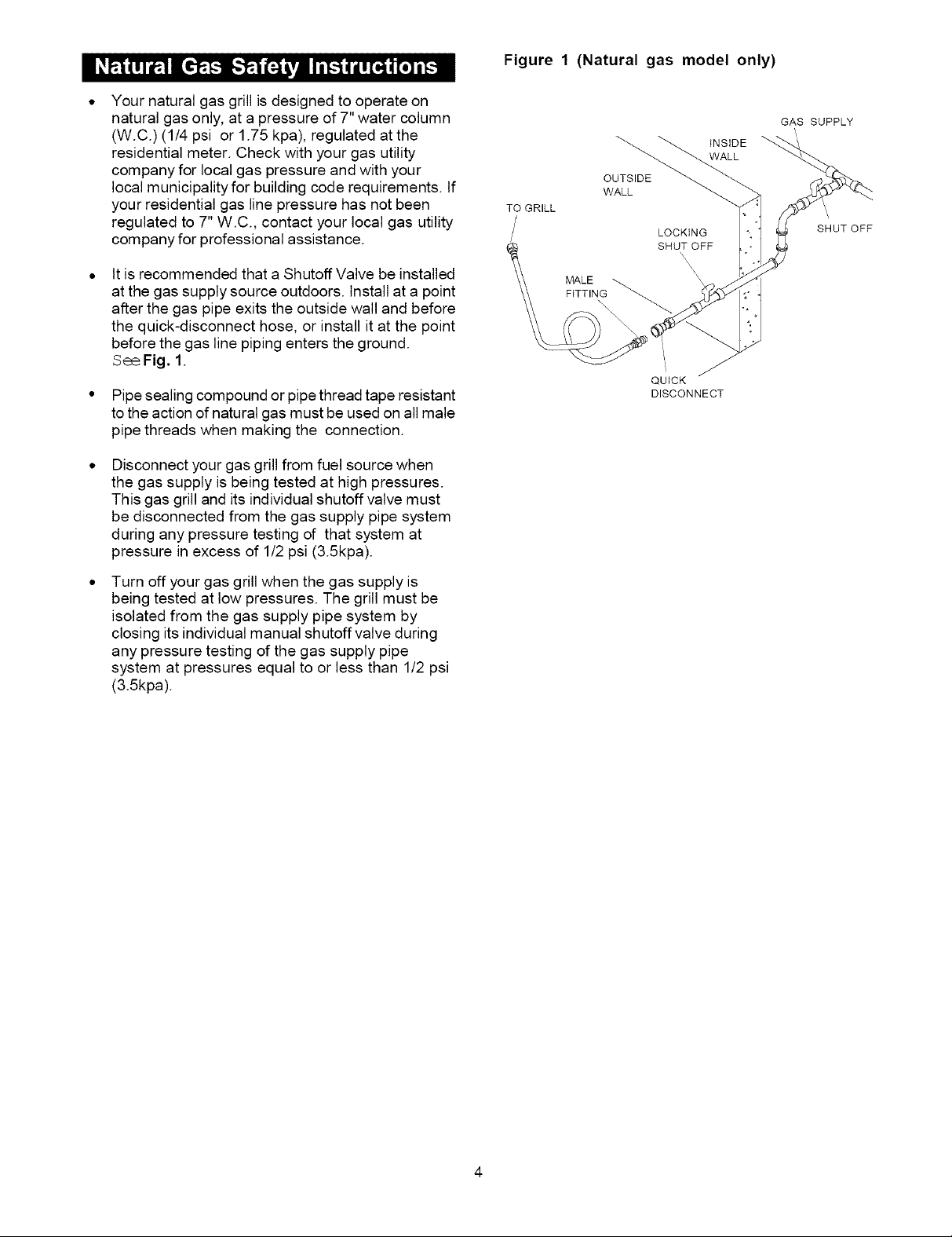
ItisrecommendedthataShutoffValvebeinstalled
atthegassupplysourceoutdoors.Installatapoint
afterthegaspipeexitstheoutsidewallandbefore
thequick-disconnecthose,orinstallitatthepoint
beforethegaslinepipingenterstheground.
SeeFig.1.
Pipe sealing compound or pipe thread tape resistant
to the action of natural gas must be used on all male
pipe threads when making the connection.
Disconnect your gas grill from fuel source when
the gas supply is being tested at high pressures.
This gas grill and its individual shutoff valve must
be disconnected from the gas supply pipe system
during any pressure testing of that system at
pressure in excess of 1/2 psi (3.5kpa).
Figure 1 (Natural gas model only)
INSIDE
WALL
OUTSIDE
WALL
TO GRILL
LOCKING
SHUT OFF
FITTING
II
i
QUICK
DISCONNECT
GAS SUPPLY
SHUT OFF
Turn off your gas grill when the gas supply is
being tested at low pressures. The grill must be
isolated from the gas supply pipe system by
closing its individual manual shutoff valve during
any pressure testing of the gas supply pipe
system at pressures equal to or less than 1/2 psi
(3.5kpa).
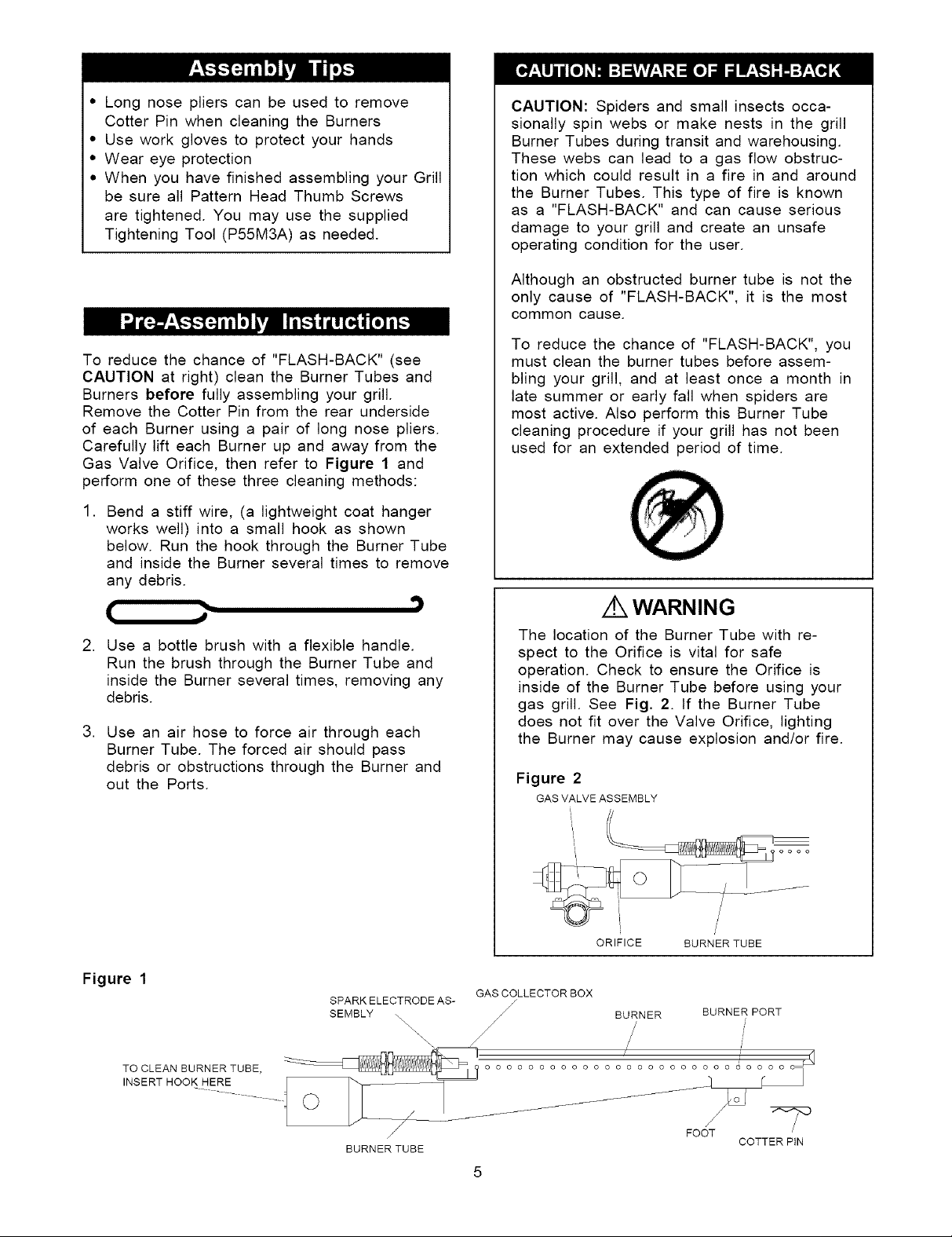
• Long nose pliers can be used to remove
Cotter Pin when cleaning the Burners
• Use work gloves to protect your hands
• Wear eye protection
• When you have finished assembling your Grill
be sure all Pattern Head Thumb Screws
are tightened. You may use the supplied
Tightening Tool (P55M3A) as needed.
To reduce the chance of "FLASH-BACK" (see
CAUTION at right) clean the Burner Tubes and
Burners before fully assembling your grill.
Remove the Cotter Pin from the rear underside
of each Burner using a pair of long nose pliers.
Carefully lift each Burner up and away from the
Gas Valve Orifice, then refer to Figure 1 and
perform one of these three cleaning methods:
1. Bend a stiff wire, (a lightweight coat hanger
works well) into a small hook as shown
below. Run the hook through the Burner Tube
and inside the Burner several times to remove
any debris.
(
2. Use a bottle brush with a flexible handle.
Run the brush through the Burner Tube and
inside the Burner several times, removing any
debris.
3. Use an air hose to force air through each
Burner Tube. The forced air should pass
debris or obstructions through the Burner and
out the Ports.
CAUTION: Spiders and small insects occa-
sionally spin webs or make nests in the grill
Burner Tubes during transit and warehousing.
These webs can lead to a gas flow obstruc-
tion which could result in a fire in and around
the Burner Tubes. This type of fire is known
as a "FLASH-BACK" and can cause serious
damage to your grill and create an unsafe
operating condition for the user.
Although an obstructed burner tube is not the
only cause of "FLASH-BACK", it is the most
common cause.
To reduce the chance of "FLASH-BACK", you
must clean the burner tubes before assem-
bling your grill, and at least once a month in
late summer or early fall when spiders are
most active. Also perform this Burner Tube
cleaning procedure if your grill has not been
used for an extended period of time.
WARNING
The location of the Burner Tube with re-
spect to the Orifice is vital for safe
operation. Check to ensure the Orifice is
inside of the Burner Tube before using your
gas grill. See Fig. 2. If the Burner Tube
does not fit over the Valve Orifice, lighting
the Burner may cause explosion and/or fire.
Figure 2
GAS VALVE ASSEMBLY
Figure 1
SPARK ELECTRODE AS-
SEMBLY \\
\\\\\\\
/
BURNER TUBE
ORIFICE BURNER TUBE
GAS COLLECTOR BOX
J
BURNER BURNER PORT
/ i =/
o o o o o o o _ o o o o
................
FOOT
COTTER PiN
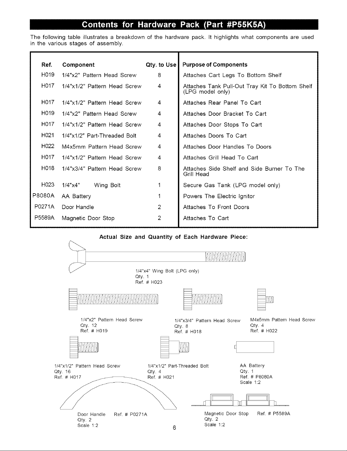
The following table illustrates a breakdown of the hardware pack. It highlights what components are used
in the various stages of assembly.
Ref. Component Qty. to Use
H019 1/4"x2" Pattern Head Screw 8
H017 1/4"xl/2" Pattern Head Screw 4
H017 1/4"xl/2" Pattern Head Screw 4
H019 1/4"x2" Pattern Head Screw 4
H017 1/4"xl/2" Pattern Head Screw 4
H021 1/4"xl/2" Part-Threaded Bolt 4
H022 M4x5mm Pattern Head Screw 4
H017 1/4"xl/2" Pattern Head Screw 4
H018 1/4"x3/4" Pattern Head Screw 8
H023 1/4"x4" Wing Bolt
P8080A AA Battery
P0271A Door Handle
P5589A Magnetic Door Stop
Purpose of Components
Attaches Cart Legs To Bottom Shelf
Attaches Tank Pull-Out Tray Kit To Bottom Shelf
(LPG model only)
Attaches Rear Panel To Cart
Attaches Door Bracket To Cart
Attaches Door Stops To Cart
Attaches Doors To Cart
Attaches Door Handles To Doors
Attaches Grill Head To Cart
Attaches Side Shelf and Side Burner To The
Grill Head
1
1
2
2
Secure Gas Tank (LPG model only)
Powers The Electric Ignitor
Attaches To Front Doors
Attaches To Cart
Actual Size and Quantity of Each Hardware Piece:
1/4"x4" Wing Bolt (LPG only)
Qty. 1
Ref. # H023
1/4"x2" Pattern Head Screw
Qty. 12
Ref. # H019
1/4"xl/2" Pattern Head Screw 1/4"xl/2" Part-Threaded Bolt AA Battery
Qty. 16 Qty. 4 Qty. 1
Ref. # H017 Ref. # H021 Ref. # P8080A
1/4"x3/4" Pattern Head Screw M4x5mm Pattern Head Screw
Qty. 8 Qty. 4
Ref. # H018 Ref. # H022
Scale 1:2
Door Handle
Qty. 2
Scale 1:2
Ref. # P0271A Magnetic Door Stop
Qty. 2
Scale 1:2
Ref. # P5589A
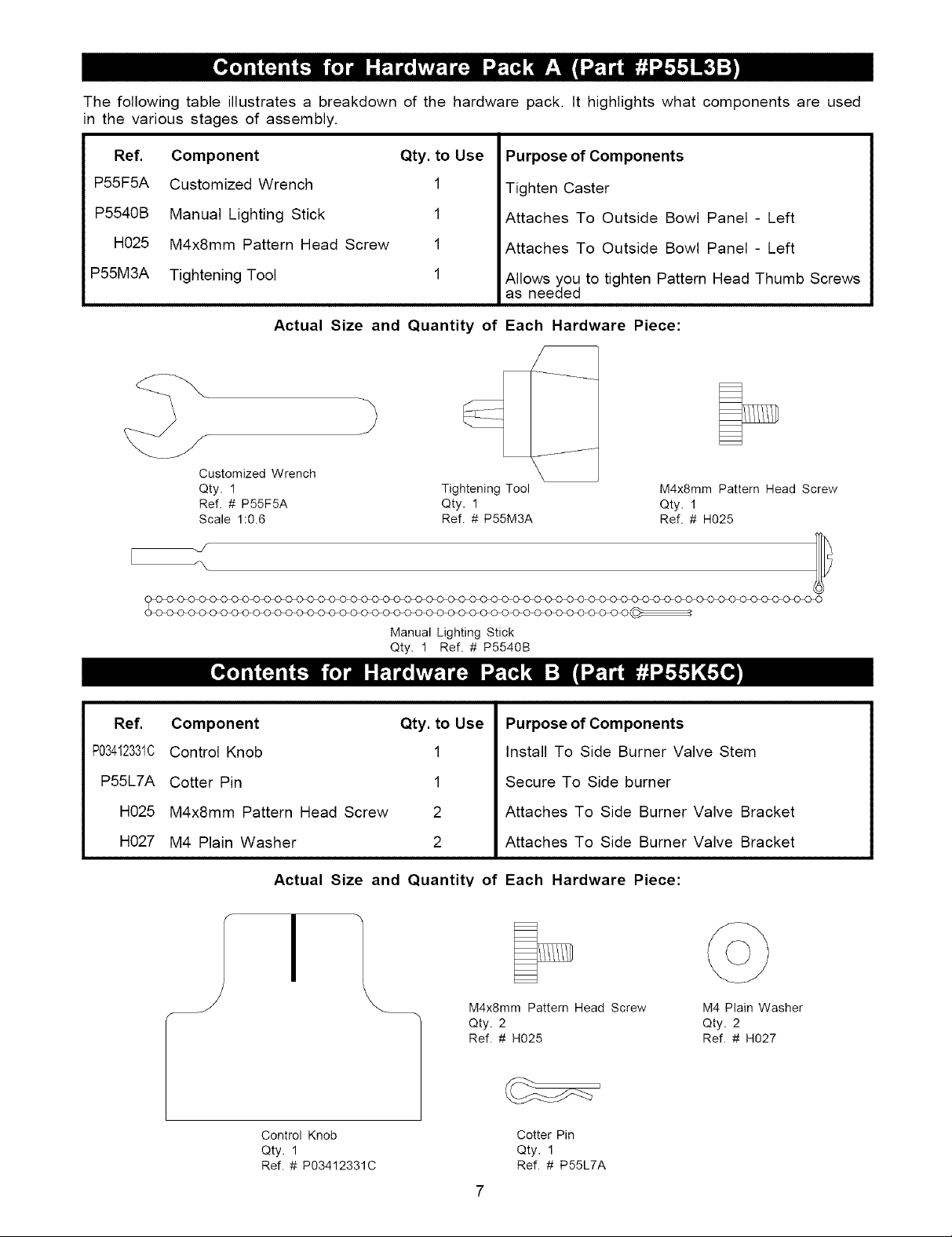
The following table illustrates a breakdown of the hardware pack. It highlights what components are used
in the various stages of assembly.
Ref.
P55F5A
P5540B
H025
P55M3A
Component Qty. to Use
Customized Wrench 1
Manual Lighting Stick 1
M4x8mm Pattern Head Screw 1
Tightening Tool 1
Actual Size and Quantity of Each Hardware Piece:
Customized Wrench
Qty. 1
Ref. # P55F5A
Scale 1:0.6
Tightening Tool M4x8mm Pattern Head Screw
Qty. 1 Qty. 1
Ref. # P55M3A Ref. # H025
Purpose of Components
Tighten Caster
Attaches To Outside Bowl Panel - Left
Attaches To Outside Bowl Panel - Left
Allows you to tighten Pattern Head Thumb Screws
as needed
Ref.
P03412331C
P55L7A
H025
H027
Manual Lighting Stick
Qty. 1 Ref. # P5540B
Component Qty. to Use
Control Knob 1
Cotter Pin 1
M4x8mm Pattern Head Screw 2
M4 Plain Washer 2
Actual Size and Quantity of Each Hardware Piece:
I
Purpose of Components
Install To Side Burner Valve Stem
Secure To Side burner
Attaches To Side Burner Valve Bracket
Attaches To Side Burner Valve Bracket
M4x8mm Pattern Head Screw M4 Plain Washer
Qty. 2 Qty. 2
Ref. # H025 Ref. # H027
Control Knob Cotter Pin
Qty. 1 Qty. 1
Ref. # P03412331C Ref. # P55L7A
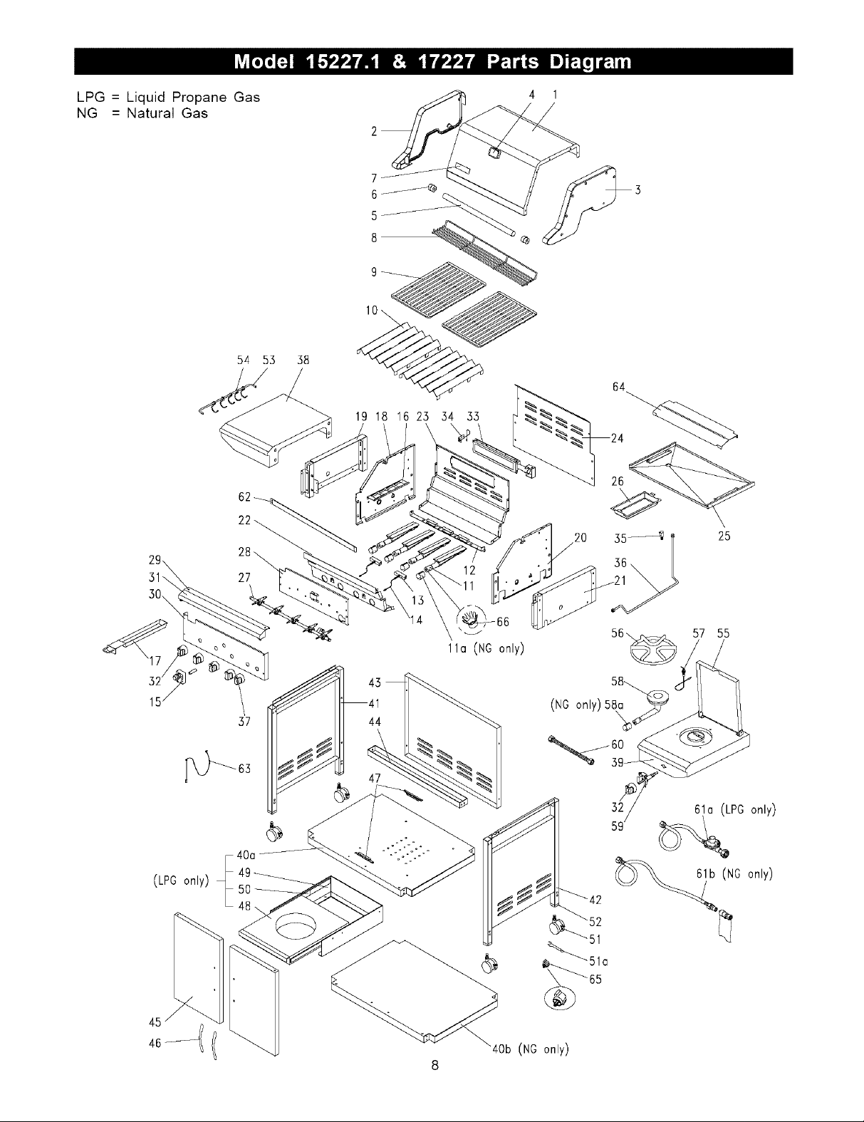
LPG = Liquid Propane Gas 4 1
NG = Natural Gas
7
54 53 38
19 18 16 23 54 33
64
26
15
(LPG only) _
37
40a
20 35_ I
25
57 55
11a (NO only)
44
(NG only) 58a,
61a (LPG only)
61b (NG only)
kOb (NG only)
REF# DESCRIPTION
PART# QTY
REF# DESCRIPTION PART# CITY
1. Stainless Steel Lid
2. Lid Side Panel - Left
3. Lid Side Panel - Right
4. Temperature Gauge
5. Lid Handle
6. Heat-Insulating Spacer
7. Name Plate
8. Secondary Cooking Rack
9. Cooking Grid - Porcelain
10. Flame Tamer - Porcelain
11. Main Burner
11 a. Air Shutter for Main Burner (NG only)
12. Main Burner Bracket
13. Gas Collector Box w/ Electrode
14. ignition Wire Set
15. Electric Ignitor
16. Smoker Drawer Bracket
17. Smoker Drawer
18. Bowl Panel- Left
19. Outside Bowl Panel - Left
20. Bowl Panel - Right
21. Outside Bowl Panel- Right
22. Bowl Panel- Front
23. Bowl Panel- Rear
24. Wind Shield
25. Grease Draining Tray
26. Grease Receptacle
27. Gas Manifold Assembly
LPG
NG
28. Heat Shield for Control Panel
29. Protective Pad - Heat Resistant
30. Control Panel
LPG
NG
31. Decorative Front Cover
32. Control Knob
33. Back Burner Assembly
34. Electrode for Back Burner
35. Orifice
LPG
NG
36. Extension Tube for Back Burner
37. Control Knob for Back Burner
38. Side Shelf
39. Side Burner Frame
40a. Bottom Shelf (LPG only)
40b. Bottom Shelf (NG only)
41. Cart Leg -Left
42. Cart Leg -Right
43. Rear Panel
44. Door Bracket
P01A1A 1
P0164A 1
P0163A 1
P0615D 1
P0251A 1
P5573A 2
P00410037C 1
P1521E 1
P1661A 2
P1749A 2
P1935F 4
P80C7A 4
P2230A 1
P2618A 2
P2637B 1
P2503G 1
P80F3A 1
P80F4A 1
P0799A 1
P0755C 1
P07A1A 1
P0758C 1
P0759B 1
P0760C 1
P80F2A 1
P2755A 1
P2741A 1
Y0060030
Y0060031
P2999A 1
P80L5A 2
P2966A
P02907351T
P2965A 1
P03412331C 5
P1948A 1
P2648A 1
P39A7A
P39A7B
P39A8A 1
P03412341C 1
P1147A 1
P1174A 1
P1074A 1
P1074B 1
P0856A 1
P0857A 1
P4356A 1
P4413A 1
45. Door Panel P4357A 2
46. Door Handle P0271A 2
47. Magnetic Door Stop P5589A 2
48. Tank Pull-Out Tray (LPG only) P4043A 1
49. Bracket for Tank Pull-Out Tray P4043B 1
(LPG only)
50. Slide (LPG only) P55J8A 2
51. Caster P5111B 4
51a. Customized Wrench P55F5A 1
52. Caster Seat P4528A 4
53. Tool Holder PBOF5A 1
54. Tool Hook P80F6C 5
55. Side Burner Lid P0199A 1
56. Pot Support P00805013B 1
57. Side Burner Electrode P2627A 1
58. Side Burner P02002054C 1
58a. Air Shutter for Side Burner (NG only)
59. Gas Valve for Side Burner
LPG
NG
60. Extension Tube for Side Burner P3983G 1
61a. Regulator and Hose (LPG only) P3632P 1
61b. NG 12' Hose Kit (NG only) P3718A 1
62. Reinforcing-Bracket for Grill Bowl PBOP1A 1
63. Manual Lighting Stick P5540B 1
64. Heat Shield for Grease Tray PBOP6A 1
65. Tightening Tool P55M3A 1
66. Heat-Insulating Ring for Main Burner Valve P06801007F 4
1
--- Owner's Manual P80103070A 1
--- Hardware Pack P55K5A 1
--- Hardware Pack A P55L3B 1
--- Hardware Pack B P55K5C 1
PBOC7B 1
P03218089G
P03218090G
1
1
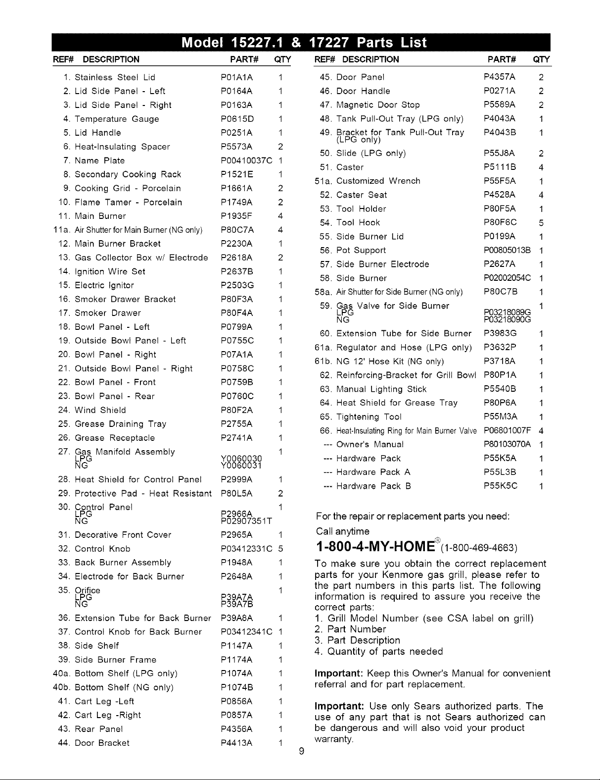
For the repair or replacement parts you need:
Call anytime
1-800-4-MY-HOM E '(1-800-469-4663)
To make sure you obtain the correct replacement
parts for your Kenmore gas grill, please refer to
1
the part numbers in this parts list. The following
information is required to assure you receive the
correct parts:
1. Grill Model Number (see CSA label on grill)
2. Part Number
3. Part Description
4. Quantity of parts needed
important: Keep this Owner's Manual for convenient
referral and for part replacement.
Important: Use only Sears authorized parts. The
use of any part that is not Sears authorized can
be dangerous and will also void your product
warranty.
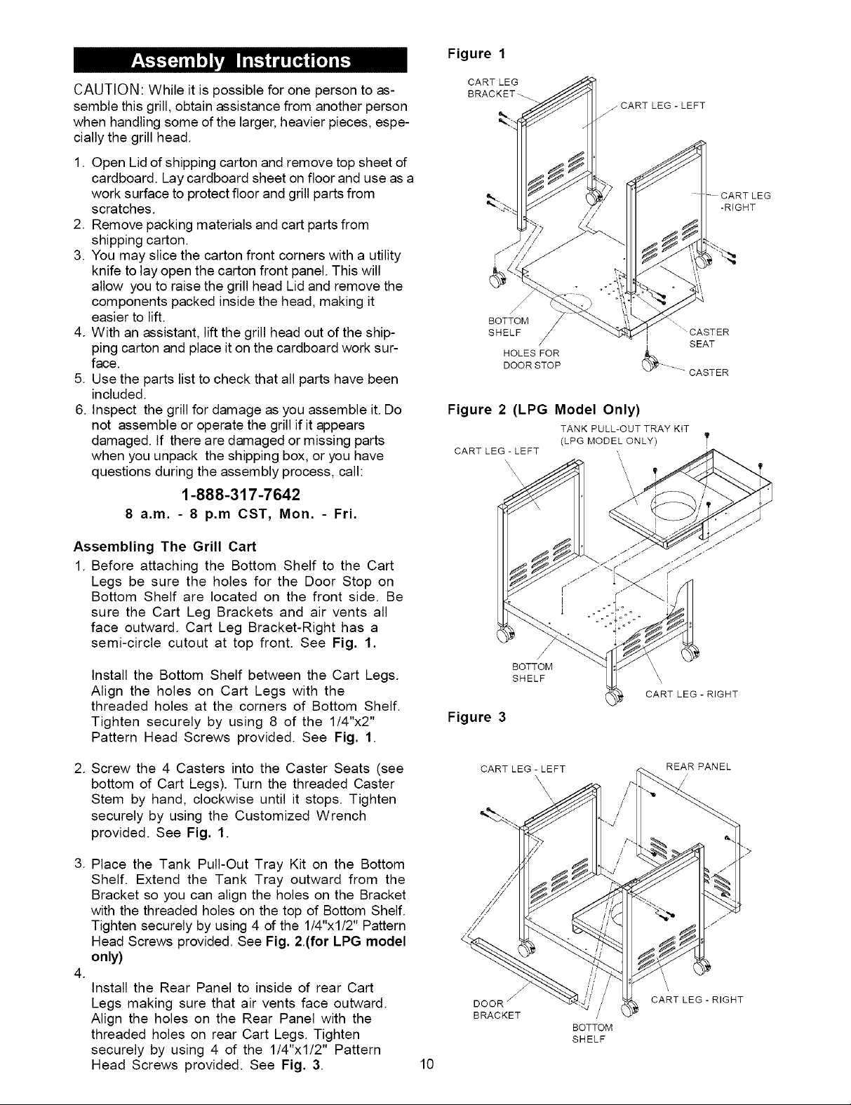
Figure 1
CAUTION:Whileitispossibleforonepersontoas-
semblethisgrill,obtainassistancefromanotherperson
when handling some of the larger, heavier pieces, espe-
cially the grill head.
1. Open Lid of shipping carton and remove top sheet of
cardboard. Lay cardboard sheet on floor and use as a
work surface to protect floor and grill parts from
scratches.
2. Remove packing materials and cart parts from
shipping carton.
3. You may slice the carton front corners with a utility
knife to lay open the carton front panel. This will
allow you to raise the grill head Lid and remove the
components packed inside the head, making it
easier to lift.
4. With an assistant, lift the grill head out of the ship-
ping carton and place it on the cardboard work sur-
face.
5. Use the parts list to check that all parts have been
included.
6. Inspect the grill for damage as you assemble it. Do
not assemble or operate the grill if it appears
damaged. If there are damaged or missing parts
when you unpack the shipping box, or you have
questions during the assembly process, call:
1-888-317-7642
8 a.m. - 8 p.m CST, Mon. - Fri.
CART LEG
BRACKET_
CART LEG-LEFT
BOTTOM
SHELF
HOLES FOR
DOOR STOP
Figure 2 (LPG Model Only)
TANK PULL-OUT TRAY KIT
(LPG MODEL ONLY
CART LEG - LEFT \\
\
-RIGHT
.........CASTER
SEAT
CASTER
Assembling The Grill Cart
1. Before attaching the Bottom Shelf to the Cart
Legs be sure the holes for the Door Stop on
Bottom Shelf are located on the front side. Be
sure the Cart Leg Brackets and air vents all
face outward. Cart Leg Bracket-Right has a
semi-circle cutout at top front. See Fig. 1.
Install the Bottom Shelf between the Cart Legs.
Align the holes on Cart Legs with the
threaded holes at the corners of Bottom Shelf.
Tighten securely by using 8 of the 1/4"x2"
Pattern Head Screws provided. See Fig. 1.
2. Screw the 4 Casters into the Caster Seats (see
bottom of Cart Legs). Turn the threaded Caster
Stem by hand, clockwise until it stops. Tighten
securely by using the Customized Wrench
provided. See Fig. 1.
3. Place
the Tank Pull-Out Tray Kit on the Bottom
Shelf. Extend the Tank Tray outward from the
Bracket so you can align the holes on the Bracket
with the threaded holes on the top of Bottom Shelf.
Tighten securely by using 4 of the 1/4"xl/2" Pattern
Head Screws provided. See Fig. 2(for LPG model
only)
.
Install the Rear Panel to inside of rear Cart
Legs making sure that air vents face outward.
Align the holes on the Rear Panel with the
threaded holes on rear Cart Legs. Tighten
securely by using 4 of the 1/4"x1/2" Pattern
Head Screws provided. See Fig. 3.
10
BOTTOM
SHELF
Figure 3
CART LEG - LEFT
BRACKET /
CART LEG - RIGHT
REAR PANEL
\
CART LEG - RIGHT
BOTTOM
SHELF
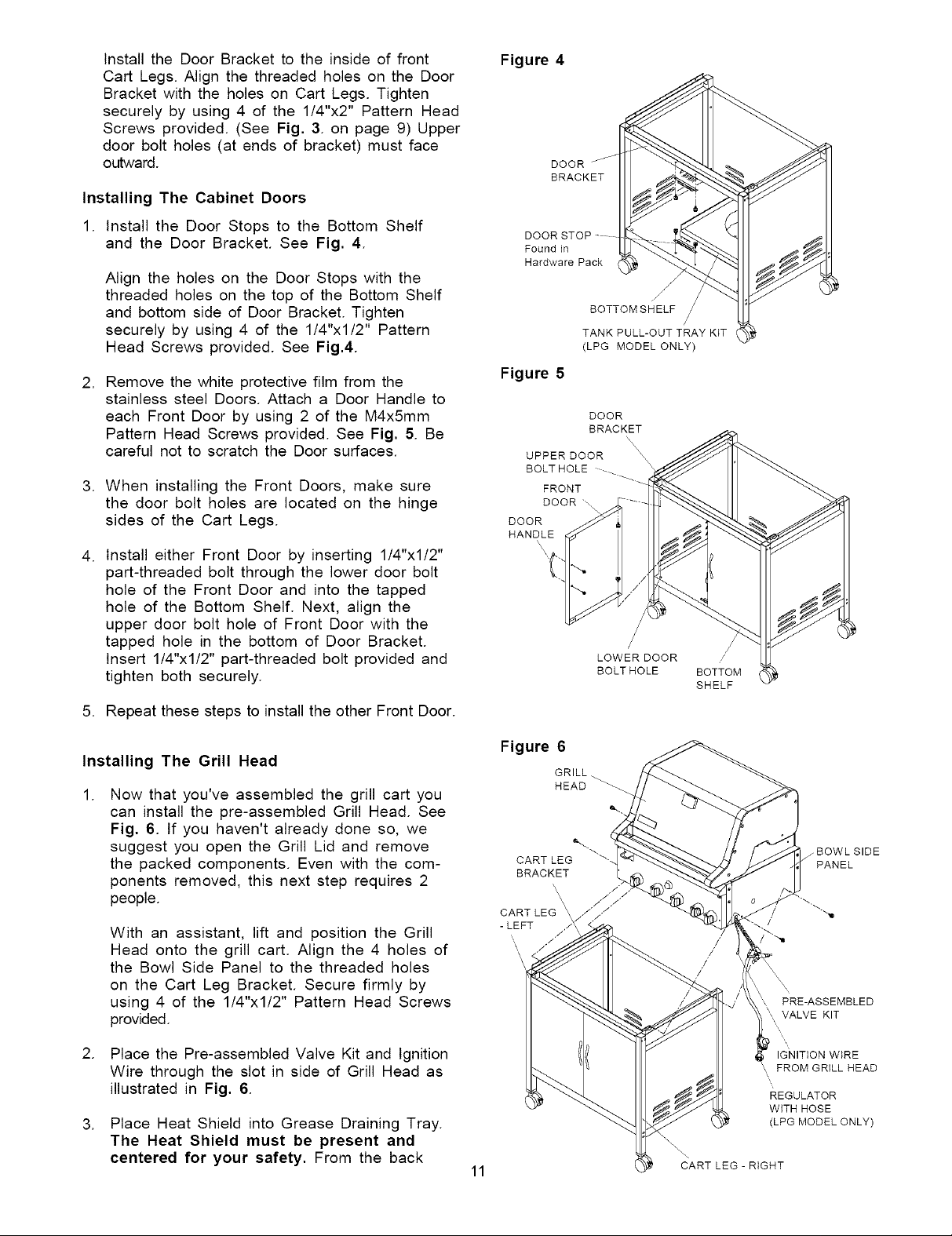
Install the Door Bracket to the inside of front
Cart Legs. Align the threaded holes on the Door
Bracket with the holes on Cart Legs. Tighten
securely by using 4 of the 1/4"x2" Pattern Head
Screws provided. (See Fig. 3. on page 9) Upper
door bolt holes (at ends of bracket) must face
outward.
Installing The Cabinet Doors
Figure 4
DOOR
BRACKET
1. Install the Door Stops to the Bottom Shelf
and the Door Bracket. See Fig. 4.
Align the holes on the Door Stops with the
threaded holes on the top of the Bottom Shelf
and bottom side of Door Bracket. Tighten
securely by using 4 of the 1/4"xl/2" Pattern
Head Screws provided. See Fig.4.
2. Remove the white protective film from the
stainless steel Doors. Attach a Door Handle to
each Front Door by using 2 of the M4x5mm
Pattern Head Screws provided. See Fig. 5. Be
careful not to scratch the Door surfaces.
3. When installing the Front Doors, make sure
the door bolt holes are located on the hinge
sides of the Cart Legs.
4. Install either Front Door by inserting 1/4"xl/2"
part-threaded bolt through the lower door bolt
hole of the Front Door and into the tapped
hole of the Bottom Shelf. Next, align the
upper door bolt hole of Front Door with the
tapped hole in the bottom of Door Bracket.
Insert 1/4"x1/2" part-threaded bolt provided and
tighten both securely.
DOOR
Found in
Hardware Pack
BOTTOM SHELF /
TANK PULL-OUT TRAY KIT
(LPG MODEL ONLY)
Figure 5
DOOR
BRACKET
UPPER DOOR
BOLTHOLE --_
FRONT
DOOR\.
DOOR
HANDLE
/
LOWER DOOR /
BOLT HOLE BOTTOM
SHELF
5. Repeat these steps to install the other Front Door.
Installing The Grill Head
Now that you've assembled the grill cart you
can install the pre-assembled Grill Head. See
Fig. 6. tf you haven't already done so, we
suggest you open the Grill Lid and remove
the packed components. Even with the com-
ponents removed, this next step requires 2
people.
With an assistant, lift and position the Grill
Head onto the grill cart. Align the 4 holes of
the Bowl Side Panel to the threaded holes
on the Cart Leg Bracket. Secure firmly by
using 4 of the 1/4"x1/2" Pattern Head Screws
provided.
2. Place the Pre-assembled Valve Kit and Ignition
Wire through the slot in side of Grill Head as
illustrated in Fig. 6.
3. Place Heat Shield into Grease Draining Tray.
The Heat Shield must be present and
centered for your safety. From the back
Figure 6
CART LEG
BRACKET
CART LEG \ /'//
- LEFT
'\
\
\
11
GRILL.
HEAD
'\ i ,
\ / ,/
\ / ,/
PRE-ASSEMBLED
\X VALVE KIT
IGNITION WIRE
FROM GRILL HEAD
REGULATOR
WITH HOSE
(LPG MODEL ONLY)
CART LEG - RIGHT
 Loading...