

Kenmore 141.15225 Owner's Manual
Owner'sManual
LiquidPropaneGasGrill
Model 141.15225
®
/_ WARNING:
Read this Owner's Manual carefully and be sure
your gas grill is properly assembled, installed and
maintained. Failure to follow these instructions
could result in serious bodily injury and!or property
damage. This gas grill is intended for outdoor use
only and is not intended to be installed in or on
recreational vehicles or boats.
Note to Installer: Leave this Owner's Manual
with consumer after delivery and/or installation.
Note to Consumer: Leave this Owner's Manual
in a convenient place for future reference.
Sears, Roebuck and Co.,
Hoffman Estates, IL 60179 U.S.A.
P80136003A - Date 2003/08/05
Warranty ..................................................... 2
Safety Instructions ...................................... 2
Hardware, Parts Diagram and Lists ..... 5
Assembly Instructions ................................. 9
Lighting Instructions .................................. 14
Cleaning and Maintenance Instructions .... 16
Frequently Asked Questions .................. 18
Cooking Instructions ................................ 19
Cooking Guide and Recipes ................ 20
Full 1-Year Warranty on Grill
For one year from the date of purchase Sears will
repair or replace, at our option, any grill part
(except for paint loss, rusting and ignitor battery)
that is defective in material or workmanship.
Limited Warranty on Selected Grill Parts
From one year after the date of purchase for the
designated time periods listed below, Sears will
replace the following gdll parts if they are defective
in material or workmanship. You will be charged for
labor.
Z_WARNING
Combustion byproducts produced when using
this product contain chemicals known to the
State of California to cause cancer, birth
defects, or other reproductive harm.
/_WARNING
Failure to comply with these instructions
could result in a fire or explosion that
could cause serious bodily injury, death, or
property damage.
Z_WARNING
Your grill will get very hot. Never lean over
the cooking area while using your gdll. Do not
touch cooking surfaces, grill housing, Lid or any
other grill parts while the gdll is in operation, or
until the grill has cooled clown after use.
Failure to comply with these instructions
may result in serious bodily injury.
FOR YOUR SAFETY
1. Do not store or use gasoline or other flam-
mable material and liquids in the vicinity of this
or any other appliance.
2. ALP cylinder not connected for use must not
be stored in the vicinity of this or any other
appliance.
• Lifetime of Grill: Aluminum Castings (except for paint
loss)
• 1 Year: Cast Iron Burners
• 2 Years: All Other Grill Parts (except flame tamers,
cooking grids and ignitor battery)
Warranty Service
Warranty service is available by contacting the ®
nearest Sears Service Center at 1-800-4-MY-HOME
Warranty Restrictions
• This warranty is void if grill is used for com-
mercial or rental purposes.
• This grill is for use with Liquid Propane (LP)
gas only. Any attempt to convert this gdll to
natural gas is dangerous and wilt void your
product warranty.
• This warranty applies only when the grill is
used in the United States.
• This warranty gives you specific legal rights,
and you may also have other rights which vary
from state to state.
Sears, Roebuck and Co., Dept. 817WA,
Hoffman Estates, IL 60179
FOR YOUR SAFETY
If you smell gas:
1. Shut off gas to the appliance.
2. Extinguish any open flame.
3. Open Lid.
4. If odor continues, immediately call your gas
supplier or your fire department.
IMPORTANT: Your Kenmore LP Gas Grill cannot
be converted to use Natural Gas. Attempting to do
so is extremely hazardous and will also void the
grill warranty.
Grill Installation Codes
This gas grill must be installed in accordance with
all local codes. In areas without local codes, follow
the latest edition of the National Fuel Gas Code
ANSI Z223.1. and National Electdcal Code ANSI/
NFPA 70 In Canada, installation must conform to
standard CAN/CGA lb149.1 or 1-b149.2 (Installation
Code for Gas Burning Appliances and Equipment)
and all local codes.
Correct LP Gas Tank Use
LP gas gdll models are designed for use with a
standard 20 lb. Liquid Propane Gas (LP gas) tank,
not included with grill box. Never connect your gas
grill to an LP gas tank that exceeds this capacity.
A tank of approximately 12 inches in diameter by
© Sears, Roebuck and Co.
18-1/2 inches high is the maximum size LP gas
tank to use. You must use an "OPD" gas tank
which offers an Overfill Prevention Device. This
safety feature prevents the tank from being overfilled
which can cause malfunction of the LP gas tank,
regulator and/or grill.
The LP gas tank must be constructed and marked
in accordance with specifications of the U.S. Dept.
of Transportation (DOT). In Canada, the LP gas
tank must meet the Canadian Transportation and
Communications (CTC) specifications. Also be sure
to read and follow all LP instructions below.
1. The LP gas tank has a shutoff valve,
terminating in an LP gas supply tank valve
outlet, that is compatible with a Type 1 tank
connection device. The LP gas tank must
also have a safety relief device that has a
direct communication with the vapor space of
the tank.
2. The tank supply system must be arranged
for vapor withdrawal.
3. The LP gas tank used must have a collar
to protect the tank valve.
Proper Placement and Clearance of Grill
Never use your gas grill in a garage, porch, shed,
breezeway or any other enclosed area. Your gas grill
isto be used outdoors only, at least 24 inches from
the back and side of any combustible surface.
Your gas gdll should net be placed under any
surface that will burn. Do net obstruct the flow of
ventilation air around the gas grill housing.
This outdoor gas grill isnot intended to be installed in
or on recreational vehicles and/or boats.
• Never connect an unregulated LP gas tank to
your gas grill. The gas regulator assembly
supplied with your gas gdll is adjusted to have
an outlet pressure of 11" water column (W.C.)
for connection to an LP gas tank.
• Only use the regulator and hose assembly
supplied with your gas grill. Replacement
regulators and hose assemblies must be those
specified by Sears.
• Have your LP gas tank filled by a reputable
propane gas dealer and visually inspected and
re-qualified at each filling.
• Never fill the gas tank beyond 80% full.
Have your propane gas dealer check the
release valve after every filling to ensure that
it remains free of defects.
• Always keep LP gas tanks in an upright
position.
• Do not store (or use) gasoline or other flammable
vapors and liquids in the vicinity of this gas grill.
• An LP gas tank that is not connected for use must
NOT be stored on bottom shelf or in the vicinity of
this or any other gas gdll.
• Do not subject the LPgas tank to excessive heat.
• Never store an LP gas tank indoors. If you
store your gas gdll in the garage or other indoor
location, always disconnect the LP gas tank
first and store it safely outside.
• LP gas tanks must be stored outdoors in a
well-ventilated area and out of the reach of
children. Disconnected LP gas tanks must not
be stored in a building, garage or any other
enclosed area.
• When your gas gdll is not in use the gas
must be turned off at the LP gas tank.
• The regulator and hose assembly must be
inspected before each use of the grill. If there
is excessive abrasion or wear or if the hose
is cut, it must be replaced prior to the grill
being used again.
• Keep the gas regulator hose away from hot
grill surfaces and dripping grease. Avoid
unnecessary twisting of hose. Visually inspect
hose prior to each use for cuts, cracks,
excessive wear or other damage. If the hose
appears damaged do not use the gas gdll.
Call Sears at 1-800-366-PART (1-800-366-
7278) for a Sears authodzed replacement
hose.
• Never light your gas grill with the lid closed
or before checking to insure the burner tubes
are fully seated over the gas valve odfices.
• Never allow children to operate your grill. Do
not allow children to play near your grill.
Z WARNING
A strong gas smell, or the hissing sound of
gas indicates a serious problem with your
gas gdll or the LP gas tank. Failure to
immediately follow the steps listed below
could result in a fire or explosion that could
cause sedous bodily injury, death, or
property damage.
Shut off gas supply to the gas gdll.
Turn the Control Knobs to OFF position.
Put out any flame with a fire extinguisher.
Open Grill Lid.
Get away from the LP gas tank.
Do not try to fix the problem yourself.
If odor continues or you have a fire you
cannot extinguish, call your fire department.
Do not call near the LP gas tank because
your telephone is an electdcal device and
could create a spark resulting in fire and/or
explosion.
NOTE: The normal flow of gas through the
regulator and hose assembly can create a
humming noise. A low volume of noise is
perfectly normal and wilt not interfere with
operation of the grill. If humming noise is
loud and excessive you may need to purge
air from the gas line or reset the regulator
excess gas flow device. This purging proce-
dure should be done every time a new LP
gas tank is connected to your grill. For help
with this procedure refer to page 15, step 4,
or call the Customer Service Helpline for
assistance, 8am - 8pm CST, Monday through
Friday 1-888-317-7642.
3
CAUTION:Spidersandsmallinsectsocca-
sionallyspinwebsor makenestsin the grill
BurnerTubesduringtransitandwarehousing.
Thesewebscanleadto a gasflowobstruc-
tion whichcouldresultin a fire in andaround
the BurnerTubes.Thistypeof fire is known
as a "FLASHBACK"and cancauseserious
damageto yourgrillandcreateanunsafe
operatingconditionfor theuser.
To reducethechanceof "FLASHBACK",you
mustcleanthe bumertubesbeforeassem-
blingyourgrill, andat leastoncea monthin
latesummeror earlyfall whenspidersare
mostactive.Alsoperformthis BurnerTube
cleaningprocedureif yourgrill hasnotbeen
usedfor anextendedperiodoftime.
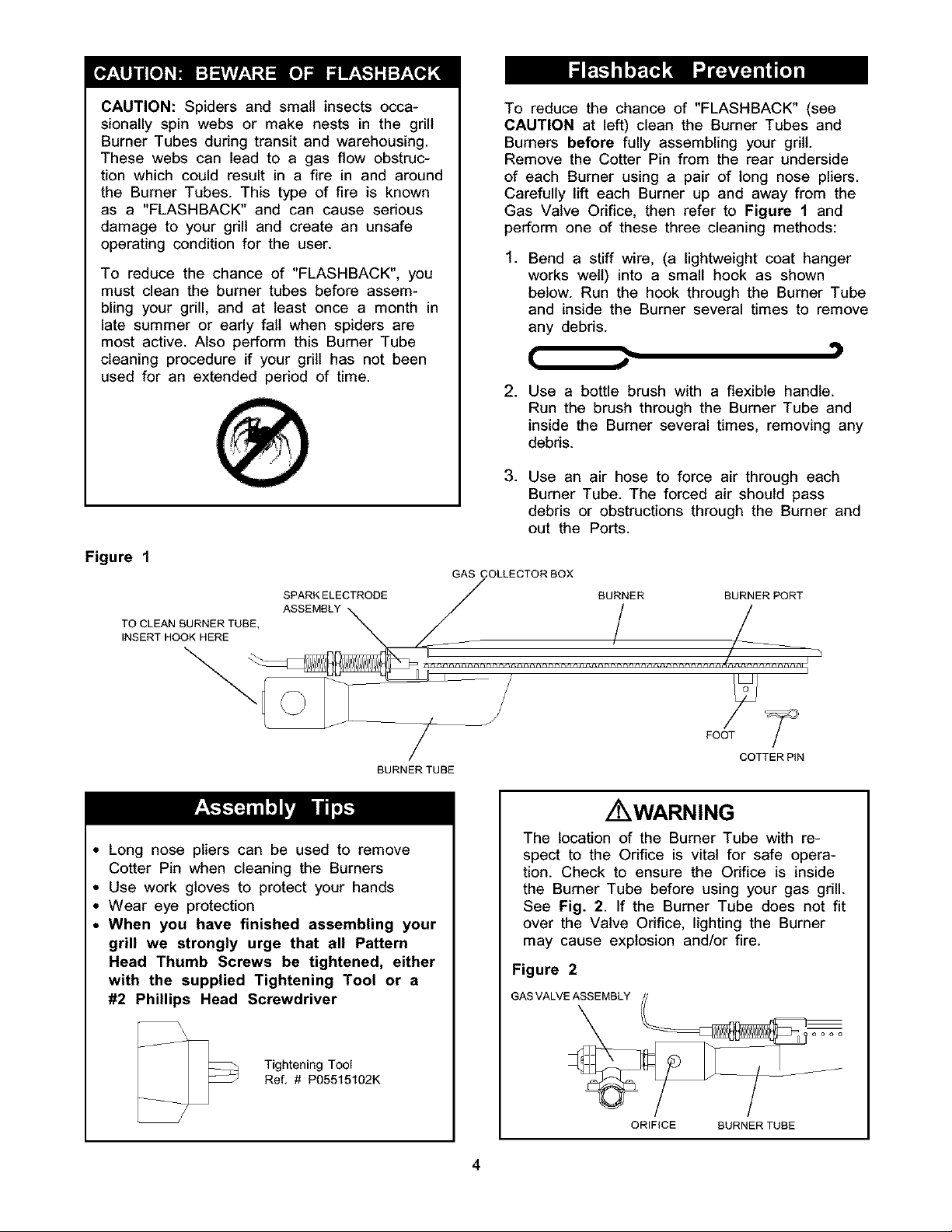
To reducethe chanceof "FLASHBACK"(see
CAUTIONat left)cleanthe BurnerTubesand
Burnersbeforefullyassemblingyourgrill.
Removethe CotterPinfromtherearunderside
of eachBurnerusinga pairof longnosepliers.
Carefullylift eachBurnerup andawayfromthe
GasValveOrifice,thenreferto Figure1 and
performoneof thesethreecleaningmethods:
.
Bend a stiff wire, (a lightweight coat hanger
works well) into a small hook as shown
below. Run the hook through the Burner Tube
and inside the Burner several times to remove
any debris.
. Use a bottle brush with a flexible handle.
Run the brush through the Burner Tube and
inside the Burner several times, removing any
debris.
.
Use an air hose to force air through each
Bumer Tube. The forced air should pass
debris or obstructions through the Burner and
out the Ports.
Figure 1
SPARKELECTROOE BURNER BURNERPORT
TO CLEAN BURNER TUBE, ASSEMBLY _ / /_
INSERT HOOK HERE
BURNER TUBE
GAS COLLECTOR BOX
Z WARNING
Long nose pliers can be used to remove
Cotter Pin when cleaning the Burners
Use work gloves to protect your hands
Wear eye protection
When you have finished assembling your
grill we strongly urge that all Pattern
Head Thumb Screws be tightened, either
with the supplied Tightening Tool or a
#2 Phillips Head Screwdriver
The location of the Burner Tube with re-
spect to the Orifice is vital for safe opera-
tion. Check to ensure the Orifice is inside
the Burner Tube before using your gas grill.
See Fig. 2. If the Burner Tube does not fit
over the Valve Orifice, lighting the Burner
may cause explosion and/or fire.
Figure 2
GAS VALVE ASSEMBLY
Tightening Tool
Ref, # P05515102K
ORIFICE BURNER TUBE
4
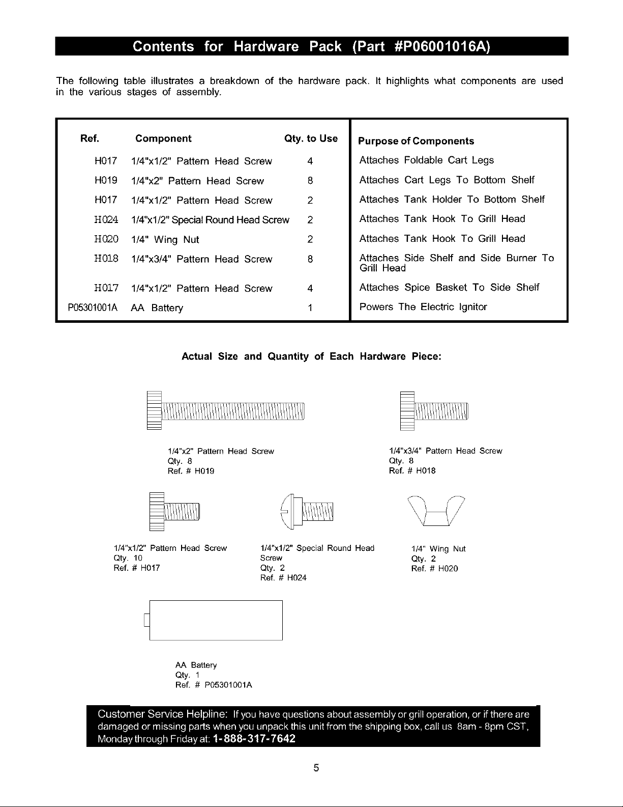
The following table illustrates a breakdown of the hardware pack. It highlights what components are used
in the various stages of assembly.
Ref.
H017
H019
H017
H024
H020
H018
H017
P05301001A
Component Qty. to Use
1/4"xl/2" Pattern Head Screw 4
1/4"x2" Pattern Head Screw 8
1/4"xl/2" Pattern Head Screw 2
1/4"xl/2" Special Round Head Screw 2
1/4" Wing Nut 2
1/4"x3/4" Pattern Head Screw 8
1/4"xl/2" Pattern Head Screw
AA Battery
4
1
Actual Size and Quantity of Each Hardware Piece:
Purpose of Components
Attaches Foldable Cart Legs
Attaches Cart Legs To Bottom Shelf
Attaches Tank Holder To Bottom Shelf
Attaches Tank Hook To Grill Head
Attaches Tank Hook To Grill Head
Attaches Side Shelf and Side Burner To
Grill Head
Attaches Spice Basket To Side Shelf
Powers The Electric Ignitor
1/4"x2" Pattern Head Screw
Qty, 8
Re[ # H019
1/4"xl/2" Pattern Head Screw
Qty. 10
Ref. # H017
AA Battery
Qty. 1
Ref. # P05301001A
1/4"xl/2" Special Round Head
Screw
Qty. 2
Ref. # H024
1/4"x3/4" Pattern Head Screw
Qty. 8
Ref. # H018
1/4" Wing Nut
Qty. 2
Ref. # H020
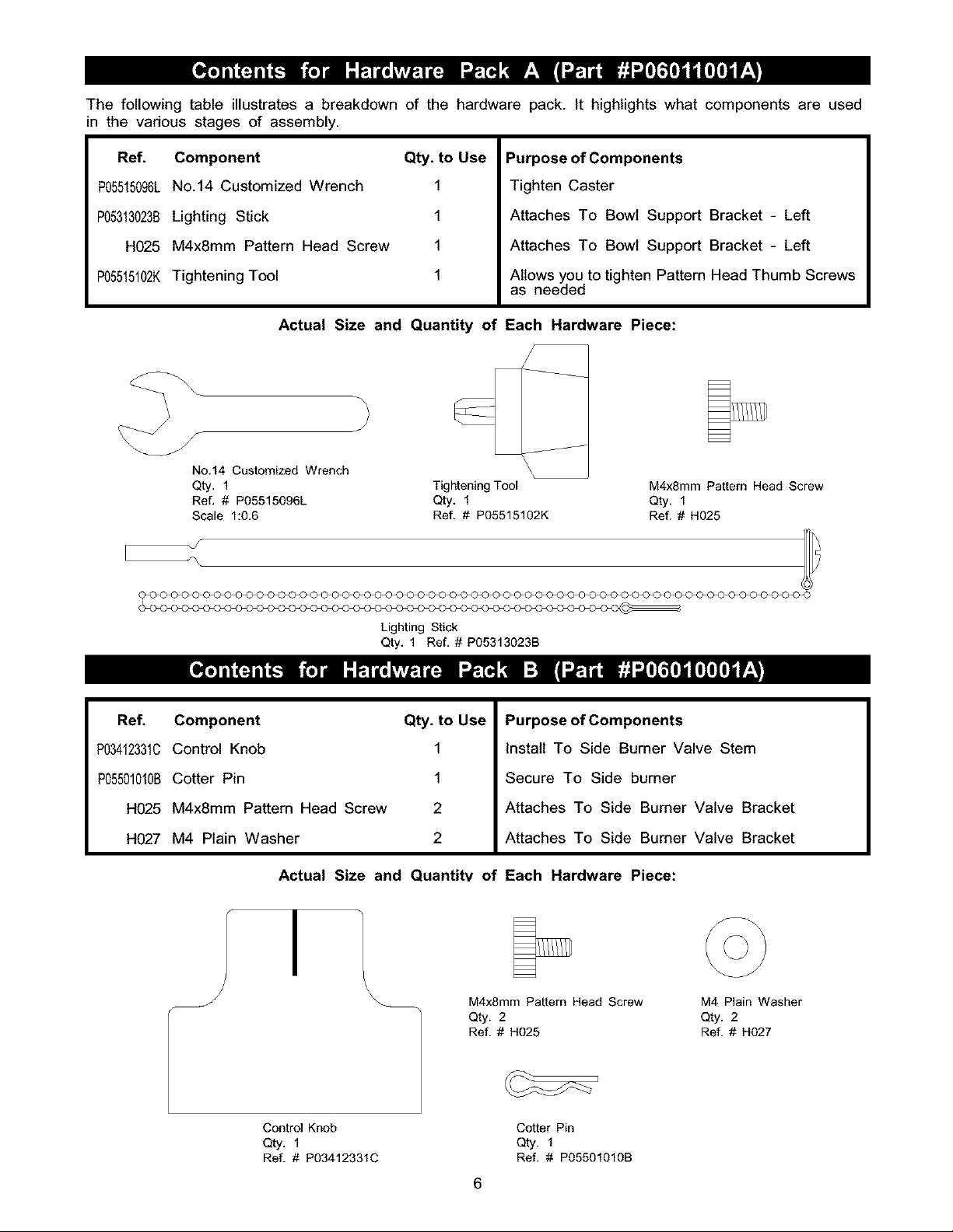
The following table illustrates a breakdown of the hardware pack. It highlights what components are used
in the various stages of assembly.
Ref. Component Qty. to Use
P05515096LNo.14 Customized Wrench 1
P05313023BLighting Stick 1
H025 M4x8mm Pattern Head Screw 1
P05515102KTightening Tool 1
Actual Size and Quantity of Each Hardware Piece:
)
/
J
No.14 Customized Wrench
Qty, 1
Ref. # PO5515096L
Scale 1:0.6
Purpose of Components
Tighten Caster
Attaches To Bowl Support Bracket - Left
Attaches To Bowl Support Bracket - Left
Allows you to tighten Pattern Head Thumb Screws
as needed
J
Tightening Tool
Qty. 1
Ref. # PO5515102K
/
M4xSmm Pattern Head Screw
Qty. 1
Ref. # H025
Lighting Stick
Qty. 1 Ref. # PO5313023B
Ref. Component Qty. to Use
P03412331CControl Knob 1
P05501010BCotter Pin 1
H025 M4x8mm Pattern Head Screw 2
H027 M4 Plain Washer 2
Actual Size and Quantity of Each Hardware Piece:
/
I
\
Purpose of Components
Install To Side Burner Valve Stem
Secure To Side burner
Attaches To Side Burner Valve Bracket
Attaches To Side Burner Valve Bracket
M4x8mm Pattern Head Screw M4 Plain Washer
Qty. 2 Qty. 2
Ref. # H025 Ref. # H027
Control Knob Cotter Pin
Qty. 1 Qty. 1
Ref. # P03412331C Ref. # PO5501010B
6
22
10
1
17
21
40\
44 _ __,,_
33a_
46_\
4b
7
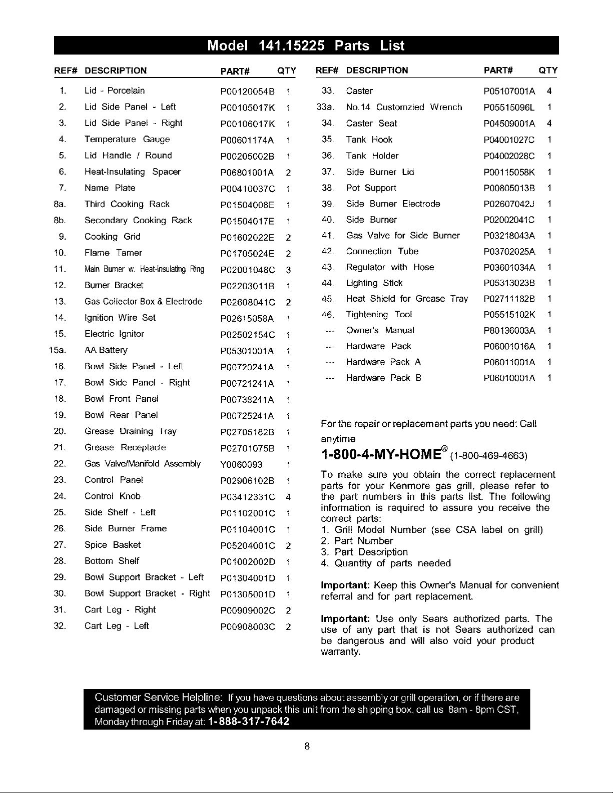
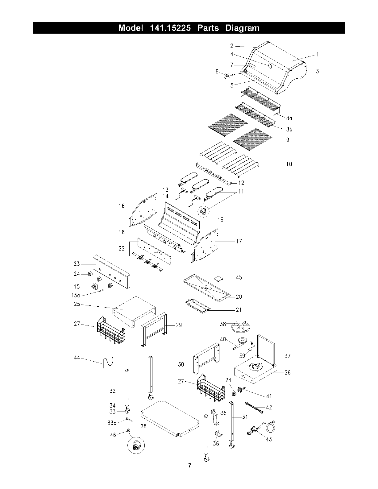
REF# DESCRIPTION
PART# QTY
REF# DESCRIPTION PART# QTY
1, Lid - Porcelain
2, Lid Side Panel - Left
3, Lid Side Panel - Right
4, Temperature Gauge
5, Lid Handle / Round
6, Heat-Insulating Spacer
7, Name Plate
8a. Third Cooking Rack
8b. Secondary Cooking Rack
9, Cooking Grid
10. Flame Tamer
11. Main Burnerw. Heat-lnsulatingRing
12. Burner Bracket
13. Gas Collector Box & Electrode
14. Ignition Wire Set
15. Electric Ignitor
15a. AA Battery
16. Bowl Side Panel - Left
17. Bowl Side Panel - Right
18. Bowl Front Panel
19. Bowl Rear Panel
20. Grease Draining Tray
21. Grease Receptacle
22. Gas Valve/Manifold Assembly
23. Control Panel
24. Control Knob
25. Side Shelf - Left
26. Side Burner Frame
27. Spice Basket
28. Bottom Shelf
29. Bowl Support Bracket - Left
30. Bowl Support Bracket - Right
31. Cart Leg - Right
32. Cart Leg - Left
PO0120054B 1
PO0105017K 1
PO0106017K 1
P00601174A 1
P00205002B 1
P06801001A 2
P00410037C 1
PO1504008E 1
PO1504017E 1
PO1602022E 2
PO1705024E 2
P02001048C 3
PO2203011B 1
P02608041C 2
P02615058A 1
P02502154C 1
P05301001A 1
P00720241A 1
P00721241A 1
P00738241A 1
P00725241A 1
P02705182B 1
P02701075B 1
Y0060093 1
P02906102B 1
P03412331C 4
P01102001C 1
P01104001C 1
P05204001C 2
PO1002002D 1
PO1304001D 1
PO1305001D 1
P00909002C 2
P00908003C 2
33. Caster PO5107001A 4
33a. No.14 Customzied Wrench PO5515096L 1
34. Caster Seat PO4509001A 4
35. Tank Hook P04001027C 1
36. Tank Holder P04002028C 1
37. Side Burner Lid P00115058K 1
38. Pot Support P00805013B 1
39. Side Burner Electrode PO2607042J 1
40. Side Burner P02002041C 1
41. Gas Valve for Side Burner P03218043A 1
42. Connection Tube P03702025A 1
43. Regulator with Hose P03601034A 1
44. Lighting Stick P05313023B 1
45. Heat Shield for Grease Tray P02711182B 1
46. Tightening Tool PO5515102K 1
--- Owner's Manual P80136003A 1
--- Hardware Pack P06001016A 1
--- Hardware Pack A P06011001A 1
--- Hardware Pack B PO6010001A 1
For the repair or replacement parts you need: Call
anytime
1-800-4-MY-HeM E®(1-800-469-4663)
To make sure you obtain the correct replacement
parts for your Kenmore gas grill, please refer to
the part numbers in this parts list. The following
information is required to assure you receive the
correct parts:
1. Grill Model Number (see CSA label on grill)
2. Part Number
3. Part Description
4. Quantity of parts needed
Important: Keep this Owner's Manual for convenient
referral and for part replacement.
Important: Use only Sears authorized parts. The
use of any part that is not Sears authorized can
be dangerous and will also void your product
warranty.
8
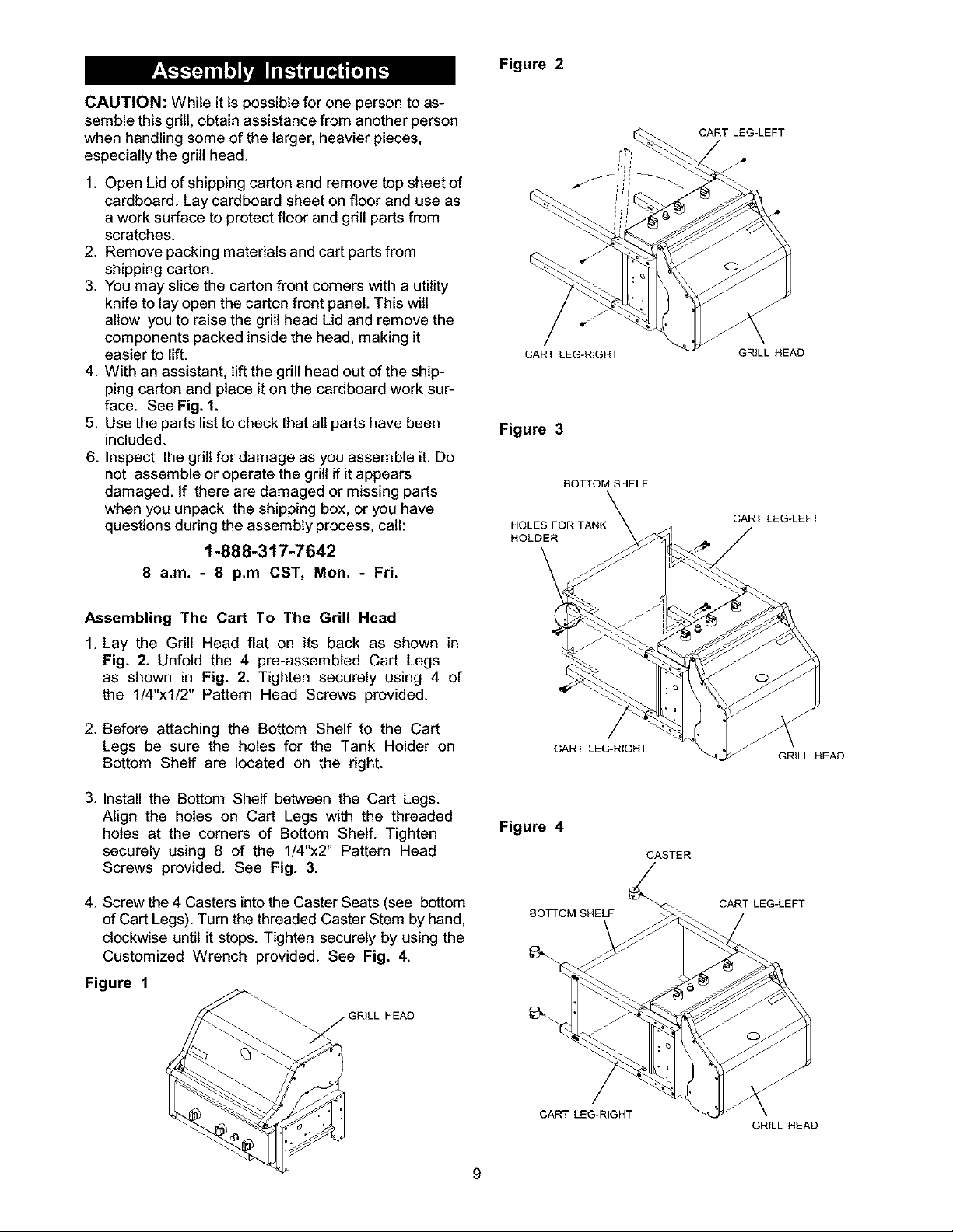
CAUTION: While it is possible for one person to as-
semble this grill, obtain assistance from another person
when handling some of the larger, heavier pieces,
especially the grill head.
1. Open Lid of shipping carton and remove top sheet of
cardboard. Lay cardboard sheet on floor and use as
a work surface to protect floor and gdll parts from
scratches.
2. Remove packing materials and cart parts from
shipping carton.
3. You may slice the carton front corners with a utility
knife to lay open the carton front panel. This will
allow you to raise the grill head Lid and remove the
components packed inside the head, making it
easier to lift.
4. With an assistant, lift the gdll head out of the ship-
ping carton and place it on the cardboard work sur-
face. See Fig. 1.
5. Use the parts list to check that all parts have been
included.
6. Inspect the grill for damage as you assemble it. Do
not assemble or operate the grill if it appears
damaged. If there are damaged or missing parts
when you unpack the shipping box, or you have
questions during the assembly process, call:
1-888-317-7642
8 a.m. - 8 p.m CST, Mon. - Fri.
Figure 2
CART LEG-RIGHT
Figure 3
BOTTOM SHELF
HOLES FOR TANK_
HOLDER
CART LEG-LEFT
GRILL HEAD
CART LEG-LEFT
Assembling The Cart To The Grill Head
1. Lay the Grill Head flat on its back as shown in
Fig. 2. Unfold the 4 pre-assembled Cart Legs
as shown in Fig. 2. Tighten securely using 4 of
the 1/4"xl/2" Pattern Head Screws provided.
2. Before attaching the Bottom Shelf to the Cart
Legs be sure the holes for the Tank Holder on
Bottom Shelf are located on the dght.
3. Install the Bottom Shelf between the Cart Legs.
Align the holes on Cart Legs with the threaded
holes at the corners of Bottom Shelf. Tighten
securely using 8 of the 1/4"x2" Pattern Head
Screws provided. See Fig. 3.
4. Screw the 4 Casters intothe Caster Seats (see bottom
of Cart Legs). Turn the threaded Caster Stem by hand,
clockwise until it stops. Tighten securely by using the
Customized Wrench provided. See Fig. 4.
Figure 1
_RILL HEAD
Figure 4
BOTTOM SHELF
_.
CART LEG-RIGHT
GRILL HEAD
CASTER
CART LEG-LEFT
CART LEG-RIGHT
GRILL HEAD
9
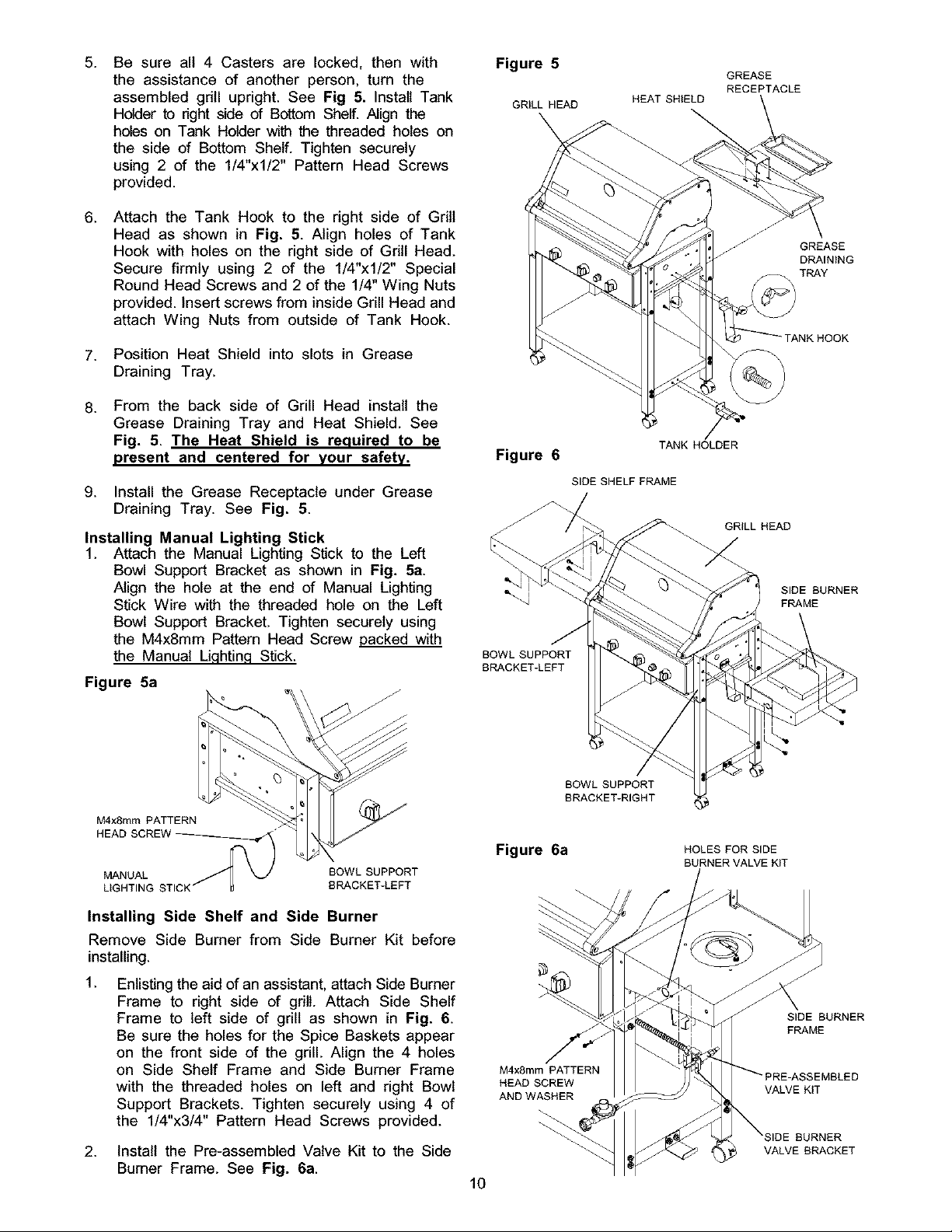
.
Be sure all 4 Casters are locked, then with
the assistance of another person, turn the
assembled gdll upright. See Fig 5. Install Tank
Holder to nght side of Bottom Shelf. Align the
holes on Tank Holder with the threaded holes on
the side of Bottom Shelf. Tighten securely
using 2 of the 1/4"xl/2" Pattern Head Screws
provided.
6.
Attach the Tank Hook to the right side of Grill
Head as shown in Fig. 5. Align holes of Tank
Hook with holes on the right side of Gdll Head.
Secure firmly using 2 of the 1/4"xl/2" Special
Round Head Screws and 2 of the 1/4" Wing Nuts
provided. Insert screws from inside Grill Head and
attach Wing Nuts from outside of Tank Hook.
7. Position Heat Shield into slots in Grease
Draining Tray.
From the back side of Grill Head install the
.
Grease Draining Tray and Heat Shield. See
Fig. 5. The Heat Shield is required to be
present and centered for your safety.
9. Install the Grease Receptacle under Grease
Draining Tray. See Fig. 5.
Installing Manual Lighting Stick
1. Attach the Manual Lighting Stick to the Left
Bowl Support Bracket as shown in Fig. 5a.
Align the hole at the end of Manual Lighting
Stick Wire with the threaded hole on the Left
Bowl Support Bracket. Tighten securely using
the M4x8mm Pattern Head Screw packed with
the Manual Lighting Stick.
Figure 5a
Figure 5
GRILL HEAD
Figure 6
BOWL SUPPORT
BRACKET-LEFT
HEAT SHtELD
SIDE SHELF FRAME
/
GREASE
RECEPTACLE
GREASE
DRAINING
TRAY
TANK HOLDER
GRILL HEAD
Z
SIDE BURNER
FRAME
M4xSmm PATTERN
HEAD SCREW__
BOWLSUPPORT
BRACKET-LEFT
Installing Side Shelf and Side Burner
Remove Side Burner from Side Burner Kit before
installing.
1.
Enlisting the aid of an assistant, attach Side Burner
Frame to right side of grill Attach Side Shelf
Frame to left side of grill as shown in Fig. 6.
Be sure the holes for the Spice Baskets appear
on the front side of the grill. Align the 4 holes
on Side Shelf Frame and Side Burner Frame
with the threaded holes on left and right Bowl
Support Brackets. Tighten securely using 4 of
the 1/4"x3/4" Pattern Head Screws provided.
2. Install the Pre-assembled Valve Kit to the Side
Bumer Frame. See Fig. 6a.
Figure 6a
M4x8mm PATTERN
HEAD SCREW
AND WASHER
10
BOWL SUPPORT
BRACKET-RIGHT
HOLES FOR SIDE
BURNER VALVE KiT
SIDE BURNER
FRAME
;EMBLED
VALVE KIT
BURNER
VALVE BRACKET
 Loading...