

Kenmore 141.152230 Owner's Manual
Owner's Manual
®
Liquid Propane Gas Grill
Model 141.152230
/_ WARNING:
Read this Owner's Manual carefully and be sure
your gas grill is properly assembled, installed and
maintained. Failure to follow these instructions
could result in serious bodily injury and/or property
damage. This gas grill is intended for outdoor use
only and is not intended to be installed in or on
recreational vehicles or boats.
Note to Installer: Leave this Owner's Manual
with consumer after delivery and/or installation.
Note to Consumer: Leave this Owner's Manual
in a convenient place for future reference.
Sears, Roebuck and Co.,
Hoffman Estates, IL 60179 U.S.A.
P47B4C - Rev: 03/28/2002
Warranty ..................................................... 2
Safety Instructions ..................................... 2
Pre-Assembly Instructions ......................... 4
Hardware, Parts Diagram and Lists ..... 5
Assembly Instructions ................................. 9
Lighting Instructions .................................. 14
Cleaning and Maintenance Instructions .... 16
Frequently Asked Questions .................. 18
Cooking Instructions ................................ 19
Cooking Guide and Recipes ................ 20
Full 1-Year Warranty on Grill
For one year from the date of purchase Sears will
repair or replace, at our option, any grill part
(except for paint loss, rusting and ignitor battery)
that is defective in material or workmanship.
Limited Warranty on Selected Grill Parts
From one year after the date of purchase for the
designated time periods listed below, Sears will
replace the following grill parts if they are defective
in material or workmanship. You wilt be charged for
labor.
• Lifetime of Grill: Aluminum Castings (except for paint
loss)
• 1 Year: Cast Iron Burners
• 2 Years: All Other Grill Parts (except flame tamers,
cooking grids and ignitor battery)
Warranty Service
Warranty service is available by contacting the ®
nearest Sears Service Center at 1-800-4-MY-HOME
,/!X,WARNING
Combustion byproducts produced when using
this product contain chemicals known to the
State of California to cause cancer, birth
defects, or other reproductive harm.
Z_ WARNI NG
Failure to comply with these instructions
could result in a fire or explosion that
could cause serious bodily injury, death, or
property damage.
Z_ WARNI NG
Your grill will get very hot. Never lean over
the cooking area while using your grill. Do not
touch cooking surfaces, grill housing, Lid or any
other grill parts while the grill is in operation, or
until the grill has cooled down after use.
Failure to comply with these instructions
may result in serious bodily injury.
FOR YOUR SAFETY
1. Do not store or use gasoline or other flam-
mable material and liquids in the vicinity of this
or any other appliance.
2. An LP cylinder not connected for use shall not
be stored in the vicinity of this or any other
appliance.
FOR YOUR SAFETY
If you smell gas:
1. Shut off gas to the appliance.
2. Extinguish any open flame.
3. Open Lid.
4. If odor continues, immediately call your gas
supplier or your fire department.
Warranty Restrictions
• This warranty is void if grill is used for commer-
cial or rental purposes.
• This grill is for use with Liquid Propane (LP)
gas only. Any attempt to convert this grill to
natural gas is dangerous and will void your
product warranty.
• This warranty applies only when the grill is
used in the United States.
• This warranty gives you specific legal rights,
and you may also have other rights which vary
from state to state.
Sears, Roebuck and Co., Dept. 817WA,
Hoffman Estates, IL 60179
Grill Installation Codes
This gas grill must be installed in accordance with
all local codes. In areas without local codes, follow
the latest edition of the National Fuel Gas Code
ANSI Z223.1. In Canada, installation must conform
to standard CAN/CGA lb149.1 or 1-b149.2 (Installa-
tion Code for Gas Burning Appliances and
Equipment) and all local codes.
Correct LP Gas Tank Use
LP gas grill models are designed for use with a
standard 20 lb. Liquid Propane Gas (LP gas) tank,
not included with grill box. Never connect your gas
grill to an LP gas tank that exceeds this capacity.
A tank of approximately 12 inches in diameter by
2 © Sears, Roebuck and Co.
18-1/2incheshighis themaximumsizeLPgas
tankto use.You must use an "OPD" gas tank
which offers an Overfill Prevention Device. This
safety feature prevents the tank from being overfilted
which can cause malfunction of the LP gas tank,
regulator and/or grill.
The LP gas tank must be constructed and marked
in accordance with specifications of the U.S. Dept.
of Transportation (DOT). In Canada, the LP gas
tank must meet the Canadian Transportation and
Communications (CTC) specifications. Also be sure
to read and follow all LP instructions below.
1. The LP gas tank has a shutoff valve,
terminating in an LP gas supply tank valve
outlet, that is compatible with a Type 1 tank
connection device. The LP gas tank must
also have a safety relief device that has a
direct communication with the vapor space of
the tank.
2. The tank supply system must be arranged
for vapor withdrawal.
3. The LP gas tank used must have a collar
to protect the tank valve.
Proper Placement and Clearance of Grill
Never use your gas grill in a garage, porch, shed,
breezeway or any other enclosed area. Your gas grill is
to be used outdoors only, at least 24 inches from the
back and side of any combustible surface. Your
gas grill should not be placed under any surface
that will burn. Do not obstruct the flow of ventilation
air around the gas grill housing.
This outdoor gas grill is not intended to be installed in
or on recreational vehicles and/or boats.
• Never connect an unregulated LP gas tank to
your gas grill. The gas regulator assembly
supplied with your gas grill is adjusted to have
an outlet pressure of 11" water column (W.C.)
for connection to an LP gas tank.
• Only use the regulator and hose assembly
supplied with your gas grill. Replacement
regulators and hose assemblies must be those
specified by Sears.
• Have your LP gas tank filled by a reputable
propane gas dealer and visually inspected and
re-qualified at each filling.
• Never fill the gas tank beyond 80% full.
Have your propane gas dealer check the
release valve after every filling to ensure that it
remains free of defects.
• Always keep LP gas tanks in an upright
position.
• Do not store (or use) gasoline or other flammable
vapors and liquids in the vicinity of this gas grill.
• An LP gas tank that is not connected for use must
NOT be stored on bottom shelf or in the vicinity of
this or any other gas grill.
• Do not subject the LP gas tank to excessive heat.
• Never store an LP gas tank indoors. If you
store your gas grill in the garage or other indoor
location, always disconnect the LP gas tank
first and store it safely outside.
• LP gas tanks must be stored outdoors in a
well-ventilated area and out of the reach of
children. Disconnected LP gas tanks must not
be stored in a building, garage or any other
enclosed area.
• When your gas grill is not in use the gas
must be turned off at the LP gas tank.
• The regulator and hose assembly must be
inspected before each use of the grill. If there
is excessive abrasion or wear or if the hose
is cut, it must be replaced prior to the grill
being used again.
• Keep the gas regulator hose away from hot
grill surfaces and dripping grease. Avoid
unnecessary twisting of hose. Visually inspect
hose prior to each use for cuts, cracks,
excessive wear or other damage. If the hose
appears damaged do not use the gas grill.
Call Sears at 1-800-366-PART (1-800-366-7278)
for a Sears authorized replacement hose.
Never light your gas grill with the lid closed
• or before checking to insure the burner tubes
are fully seated over the gas valve orifices.
Never allow children to operate your grill. Do
• not allow children to play near your grill.
WARNI NG
A strong gas smell, or the hissing sound of
gas indicates a serious problem with your
gas grill or the LP gas tank. Failure to
immediately follow the steps listed below
could result in a fire or explosion that could
cause serious bodily injury, death, or prop-
erty damage.
• Shut off gas supply to the gas grill.
• Turn the Control Knobs to OFF position.
• Put out any flame with a fire extinguisher.
• Open Grill Lid.
• Get away from the LP gas tank.
• Do not try to fix the problem yourself.
• If odor continues or you have a fire you
cannot extinguish, call your fire
department.
Do not call near the LP gas tank because
your telephone is an electrical device and
could create a spark resulting in fire
and/or explosion.
NOTE: The normal flow of gas through the
regulator and hose assembly can create a
humming noise. A low volume of noise is
perfectly normal and will not interfere with
operation of the grill. If humming noise is
loud and excessive you may need to purge
air from the gas line or reset the regulator
excess gas flow device. This purging proce-
dure should be done every time a new LP
gas tank is connected to your grill. For help
with this procedure refer to page 15, step 4,
or call the Customer Service Helpline for
assistance, 8am - 8pm CST, Monday through
Friday 1-888-317-7642.
• Longnoseplierscanbe usedto remove
CotterPinwhencleaningtheBurners
• Useworkglovestoprotectyourhands
• Weareyeprotection
• WhenyouhavefinishedassemblingyourGrill
besureall PatternHeadThumbScrewsare
tightened.Youmayusethe suppliedTighten-
ingTool(P55M3A)asneeded.
To reducethechanceof "FLASH-BACK"(see
CAUTIONat right)cleantheBurnerTubesand
Burnersbeforefullyassemblingyourgrill.
RemovetheCotterPinfromtherearunderside
of eachBurnerusinga pairof tongnosepliers.
Carefullylift eachBurnerupandawayfromthe
GasValveOrifice,thenreferto Figure1 and
performoneofthesethreecleaningmethods:
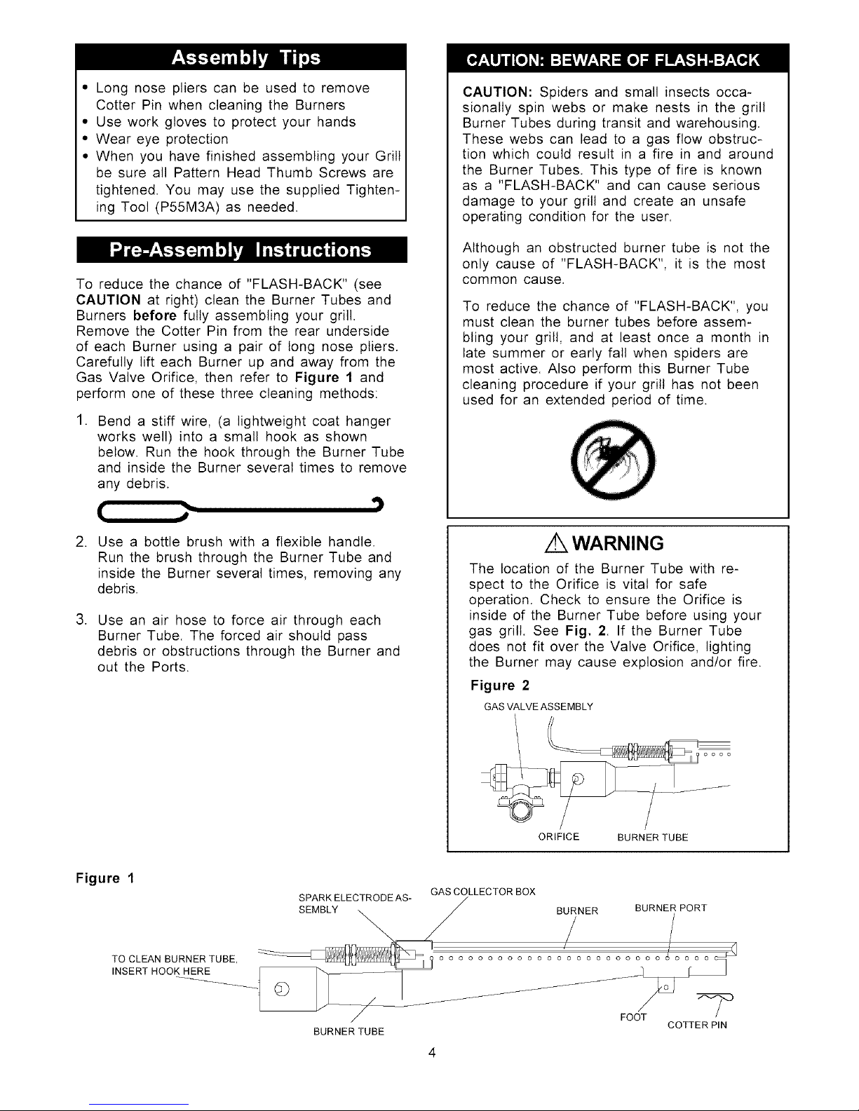
1. Benda stiffwire,(alightweightcoathanger
workswell)intoa smallhookasshown
below.Runthe hookthroughtheBurnerTube
andinsidetheBurnerseveraltimesto remove
anydebris.
t[ _,,
2. Use a bottle brush with a flexible handle.
Run the brush through the Burner Tube and
inside the Burner several times, removing any
debris.
3. Use an air hose to force air through each
Burner Tube. The forced air should pass
debris or obstructions through the Burner and
out the Ports.
CAUTION: Spiders and small insects occa-
sionally spin webs or make nests in the grill
Burner Tubes during transit and warehousing.
These webs can lead to a gas flow obstruc-
tion which could result in a fire in and around
the Burner Tubes. This type of fire is known
as a "FLASH-BACK" and can cause serious
damage to your grill and create an unsafe
operating condition for the user.
Although an obstructed burner tube is not the
only cause of "FLASH-BACK', it is the most
common cause.
To reduce the chance of "FLASH-BACK", you
must clean the burner tubes before assem-
bling your grill, and at least once a month in
late summer or early fall when spiders are
most active. Also perform this Burner Tube
cleaning procedure if your grill has not been
used for an extended period of time.
z WARNING
The location of the Burner Tube with re-
spect to the Orifice is vital for safe
operation. Check to ensure the Orifice is
inside of the Burner Tube before using your
gas grill. See Fig. 2. If the Burner Tube
does not fit over the Valve Orifice, lighting
the Burner may cause explosion and/or fire.
Figure 2
GAS VALVE ASSEMBLY
ORIFICE BURNER TUBE
Figure 1
GAS COLLECTOR BOX
SPARK ELECTRODE AS- / BURNER BURNER PORT
TO CLEAN BURNER TUBE, ,................. , _ ................ o o o o o o o o o o _
INSERT HOOK__HERE _ -- '_
L_jL _Z" FOOT
BURNER TUBE COTTER PIN
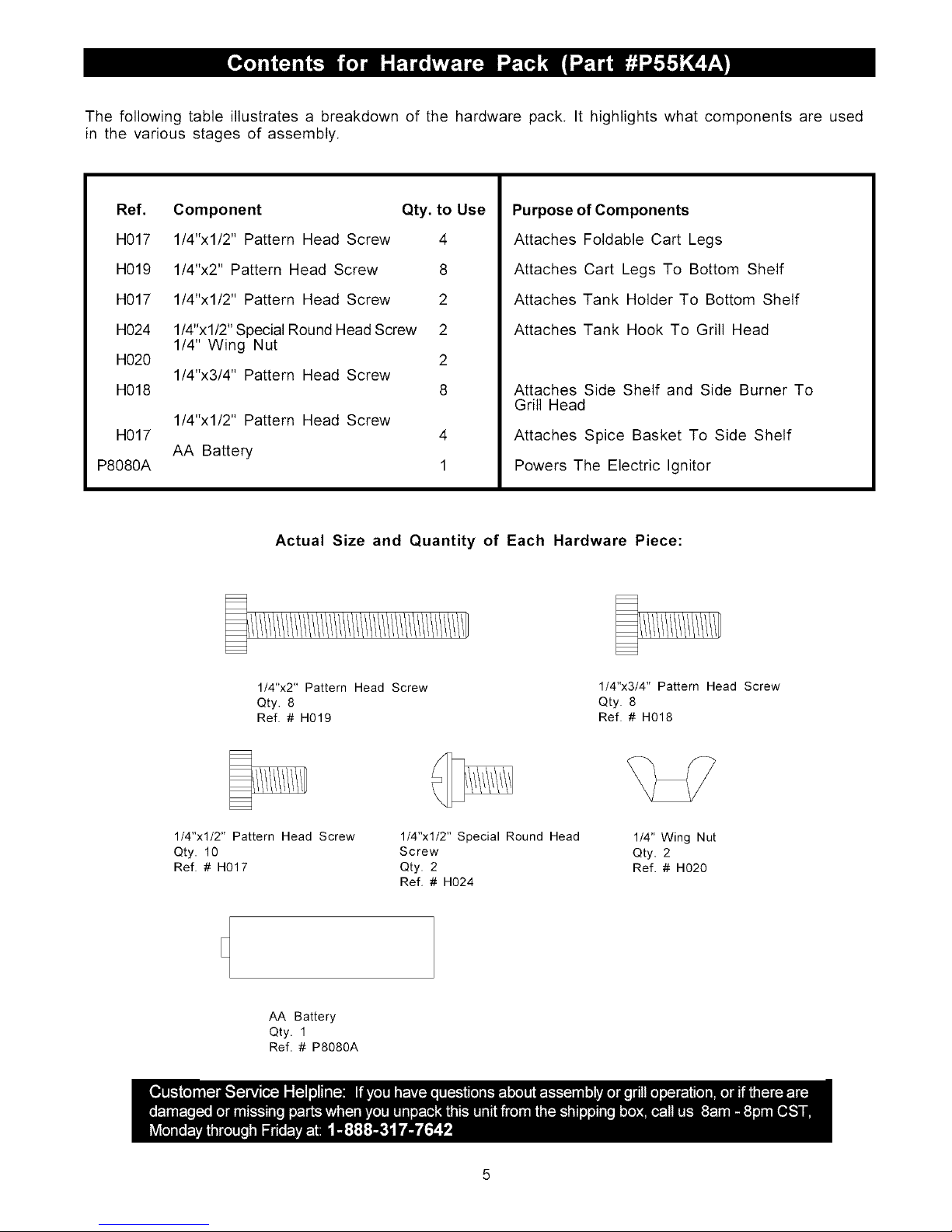
The following table illustrates a breakdown of the hardware pack. It highlights what components are used
in the various stages of assembly.
Ref.
H017
H019
H017
H024
H020
H018
H017
P8080A
Component Qty. to Use
1/4"xl/2" Pattern Head Screw 4
1/4"x2" Pattern Head Screw 8
1/4"xl/2" Pattern Head Screw 2
1/4"xl/2" Special Round Head Screw 2
1/4" Wing Nut
2
1/4"x3/4" Pattern Head Screw
8
1/4"xl/2" Pattern Head Screw
AA Battery
4
1
Purpose of Components
Attaches Foldable Cart Legs
Attaches Cart Legs To Bottom Shelf
Attaches Tank Holder To Bottom Shelf
Attaches Tank Hook To Grill Head
Attaches Side Shelf and Side Burner To
Grill Head
Attaches Spice Basket To Side Shelf
Powers The Electric Ignitor
Actual Size and Quantity of Each Hardware Piece:
1/4"x2" Pattern Head Screw
Qty. 8
Ref. # H019
1/4"x3/4" Pattern Head Screw
Qty. 8
Ref. # H018
1/4"xl/2" Pattern Head Screw
Qty. 10
Ref. # H017
1/4"xl/2" Special Round Head
Screw
Qty. 2
Ref. # H024
1/4" Wing Nut
Qty. 2
Ref. # H020
AA Battery
Qty. 1
Ref. # P8080A
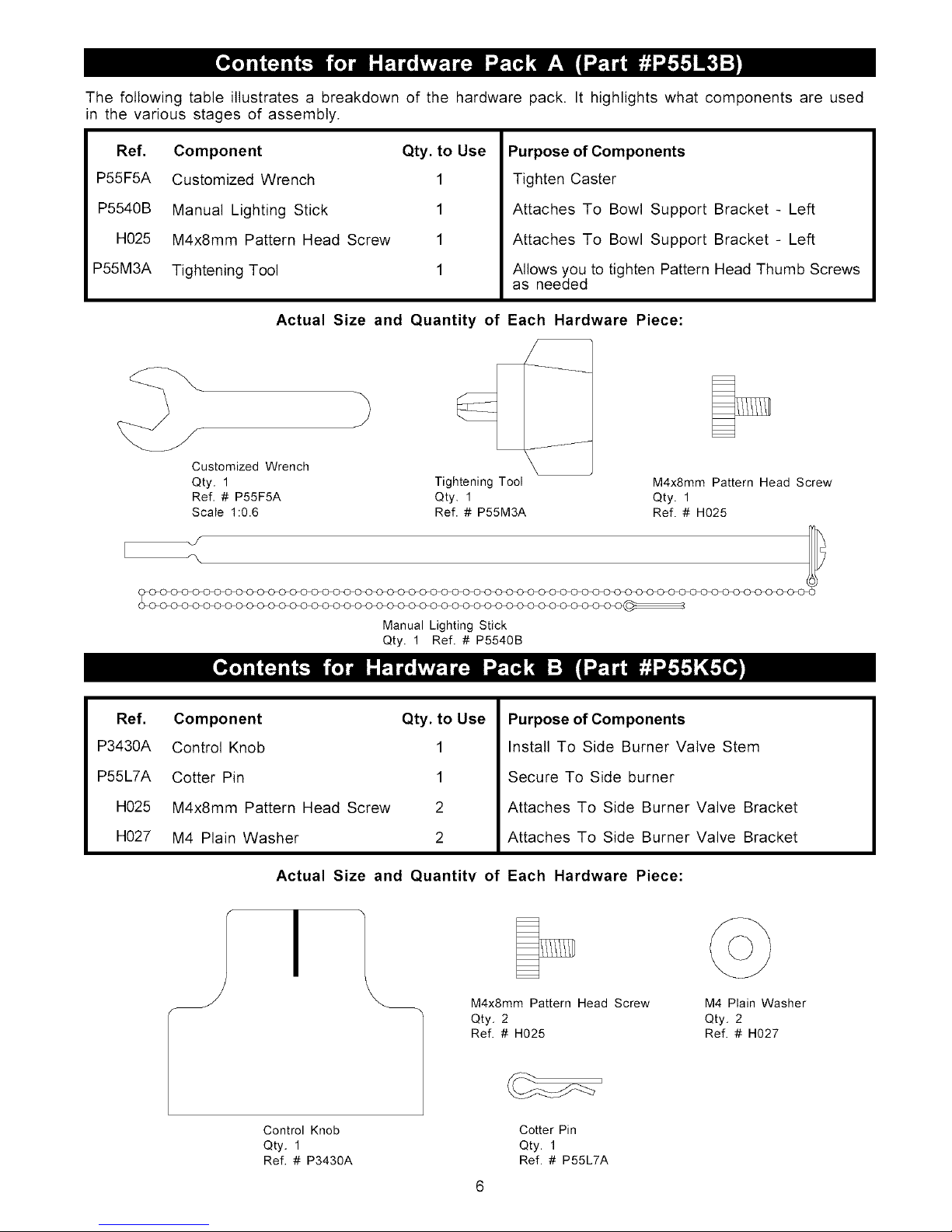
The following table illustrates a breakdown of the hardware pack. It highlights what components are used
in the various stages of assembly.
Ref. Component Qty. to Use
P55F5A Customized Wrench 1
P5540B Manual Lighting Stick 1
H025 M4x8mm Pattern Head Screw 1
P55M3A Tightening Tool 1
Purpose of Components
Tighten Caster
Attaches To Bowl Support Bracket - Left
Attaches To Bowl Support Bracket - Left
Allows you to tighten Pattern Head Thumb Screws
as needed
Actual Size and Quantity of Each Hardware Piece:
Customized Wrench
Qty. 1
Ref. # P55F5A
Scale 1:0.6
Tightening Tool M4x8mm Pattern Head Screw
Qty. 1 Qty. 1
Ref. # P55M3A Ref. # H025
Manual Lighting Stick
Qty. 1 Ref. # P5540B
Ref. Component Qty. to Use
P3430A Control Knob 1
P55L7A Cotter Pin 1
H025 M4x8mm Pattern Head Screw 2
H027 M4 Plain Washer 2
Purpose of Components
Install To Side Burner Valve Stem
Secure To Side burner
Attaches To Side Burner Valve Bracket
Attaches To Side Burner Valve Bracket
Actual Size and Quantity of Each Hardware Piece:
I
M4x8mm Pattern Head Screw M4 Plain Washer
Qty. 2 Qty. 2
Ref. # H025 Ref. # H027
Control Knob Cotter Pin
Qty, 1 Qty. 1
Ref. # P3430A Ref. # P55L7A
8b
9
10
16
18
24
19
17
7
<h
47
26
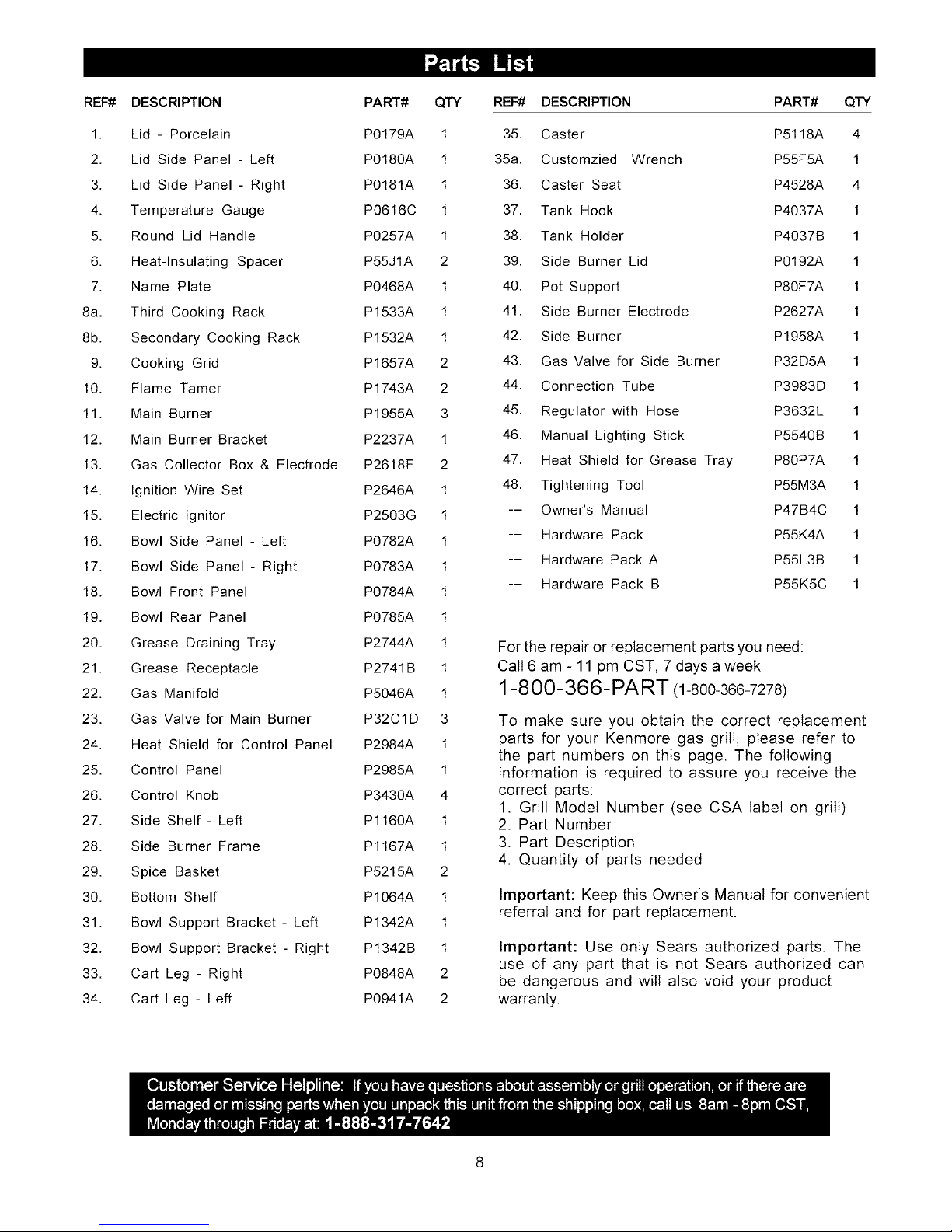
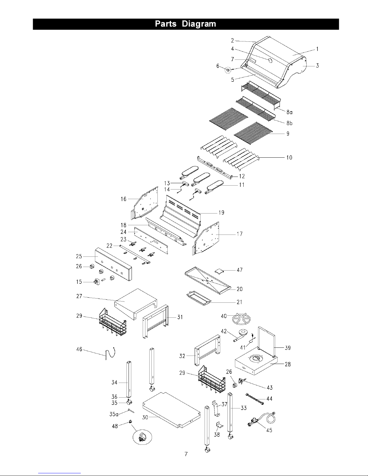
REF# DESCRIPTION PART# QTY
1. Lid- Porcelain P0179A 1
2. Lid Side Panel - Left P0180A 1
3. Lid Side Panel- Right P0181A 1
4. Temperature Gauge P0616C 1
5. Round Lid Handle P0257A 1
6. Heat-Insulating Spacer P55JIA 2
7. Name Plate P0468A 1
8a. Third Cooking Rack P1533A 1
8b. Secondary Cooking Rack P1532A 1
9. Cooking Grid P1657A 2
10. Flame Tamer P1743A 2
11. Main Burner P1955A 3
12. Main Burner Bracket P2237A 1
13. Gas Collector Box & Electrode P2618F 2
14. Ignition Wire Set P2646A 1
15. Electric Ignitor P2503G 1
16. Bowl Side Panel - Left P0782A 1
17. Bowl Side Panel- Right P0783A 1
18. Bowl Front Panel P0784A 1
19. Bowl Rear Panel P0785A 1
20. Grease Draining Tray P2744A 1
21. Grease Receptacle P2741B 1
22. Gas Manifold P5046A 1
23. Gas Valve for Main Burner P32CID 3
24. Heat Shield for Control Panel P2984A 1
25. Control Panel P2985A 1
26. Control Knob P3430A 4
27. Side Shelf- Left P1160A 1
28. Side Burner Frame P1167A 1
29. Spice Basket P5215A 2
30. Bottom Shelf P1064A 1
31. Bowl Support Bracket - Left P1342A 1
32. Bowl Support Bracket - Right P1342B 1
33. Cart Leg - Right P0848A 2
34. Cart Leg - Left P0941A 2
DESCRIPTION PART#
Caster P5118A
Customzied Wrench P55F5A
Caster Seat P4528A
Tank Hook P4037A
Tank Holder P4037B
Side Burner Lid P0192A
Pot Support P80F7A
REF#
35.
35a.
36.
37.
38.
39.
40.
41. Side Burner Electrode P2627A
42. Side Burner P1958A
43. Gas Valve for Side Burner P32D5A
44. Connection Tube P3983D
45. Regulator with Hose P3632L
46. Manual Lighting Stick P5540B
47. Heat Shield for Grease Tray P80P7A
48. Tightening Tool P55M3A
--- Owner's Manual P47B4C
--- Hardware Pack P55K4A
--- Hardware Pack A P55L3B
--- Hardware Pack B P55K5C
QTY
4
1
4
1
1
1
1
1
1
1
1
1
1
1
1
1
1
1
1
For the repair or replacement parts you need:
Call 6 am - 11 pm CST, 7 days a week
1-8 00-366-PART (1-800-366-7278)
To make sure you obtain the correct replacement
parts for your Kenmore gas grill, please refer to
the part numbers on this page. The following
information is required to assure you receive the
correct parts:
1. Grill Model Number (see CSA label on grill)
2. Part Number
3. Part Description
4. Quantity of parts needed
Important: Keep this Owner's Manual for convenient
referral and for part replacement.
Important: Use only Sears authorized parts. The
use of any part that is not Sears authorized can
be dangerous and will also void your product
warranty.
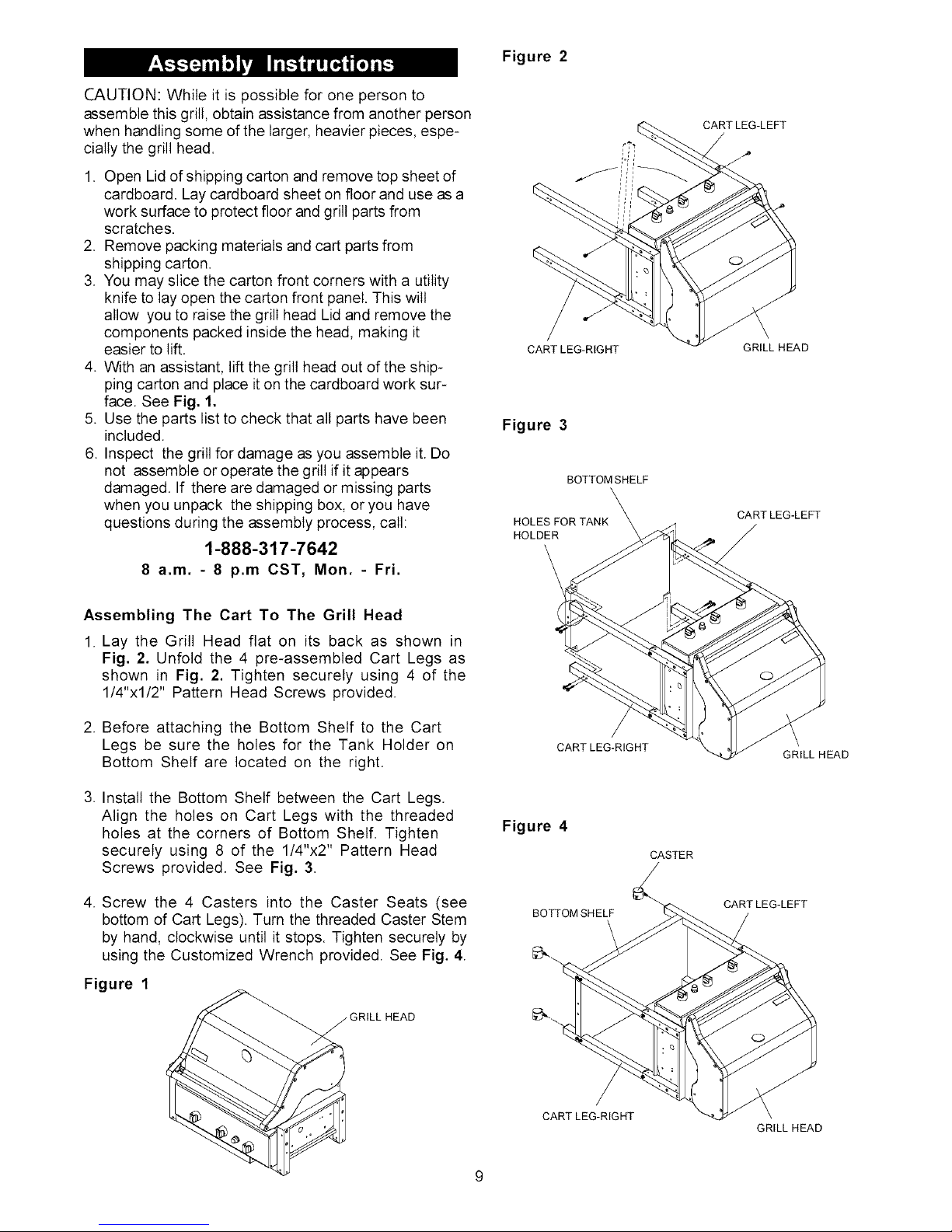
CAUTION:Whileitispossibleforonepersonto
Figure 2
assemble this grill, obtain assistance from another person
when handling some of the larger, heavier pieces, espe-
cially the grill head.
1. Open Lid of shipping carton and remove top sheet of
cardboard. Lay cardboard sheet on floor and use as a
work surface to protect floor and grill parts from
scratches.
2. Remove packing materials and cart parts from
shipping carton.
3. You may slice the carton front corners with a utility
knife to lay open the carton front panel. This wilt
allow you to raise the grill head Lid and remove the
components packed inside the head, making it
easier to lift.
4. With an assistant, lift the grill head out of the ship-
ping carton and place it on the cardboard work sur-
face. See Fig. 1.
5. Use the parts list to check that all parts have been
included.
6. Inspect the grill for damage as you assemble it. Do
not assemble or operate the grill if it appears
damaged. If there are damaged or missing parts
when you unpack the shipping box, or you have
questions during the assembly process, call:
1-888-317-7642
8 a.m. - 8 p.m CST, Mon. - Fri.
e,/-j
CART LEG-RIGHT
Figure 3
BOTTOMSHELF
HOLES FOR TANK
HOLDER
CARTLEG-LEFT
GRILL HEAD
CARTLEG-LEFT
Assembling The Cart To The Grill Head
1. Lay the Grill Head flat on its back as shown in
Fig. 2. Unfold the 4 pre-assembled Cart Legs as
shown in Fig. 2. Tighten securely using 4 of the
1/4"xl/2" Pattern Head Screws provided.
2. Before attaching the Bottom Shelf to the Cart
Legs be sure the holes for the Tank Holder on
Bottom Shelf are located on the right.
3. Install the Bottom Shelf between the Cart Legs.
Align the holes on Cart Legs with the threaded
holes at the corners of Bottom Shelf. Tighten
securely using 8 of the 1/4"x2" Pattern Head
Screws provided. See Fig. 3.
4. Screw the 4 Casters into the Caster Seats (see
bottom of Cart Legs). Turn the threaded Caster Stem
by hand, clockwise until it stops. Tighten securely by
using the Customized Wrench provided. See Fig. 4.
Figure 1
IRILL HEAD
Figure 4
CART LEG-RIGHT
CASTER
BOTTOM SHELF
GRILL HEAD
CARTLEG-LEFT
CART LEG-RIGHT
GRILL HEAD
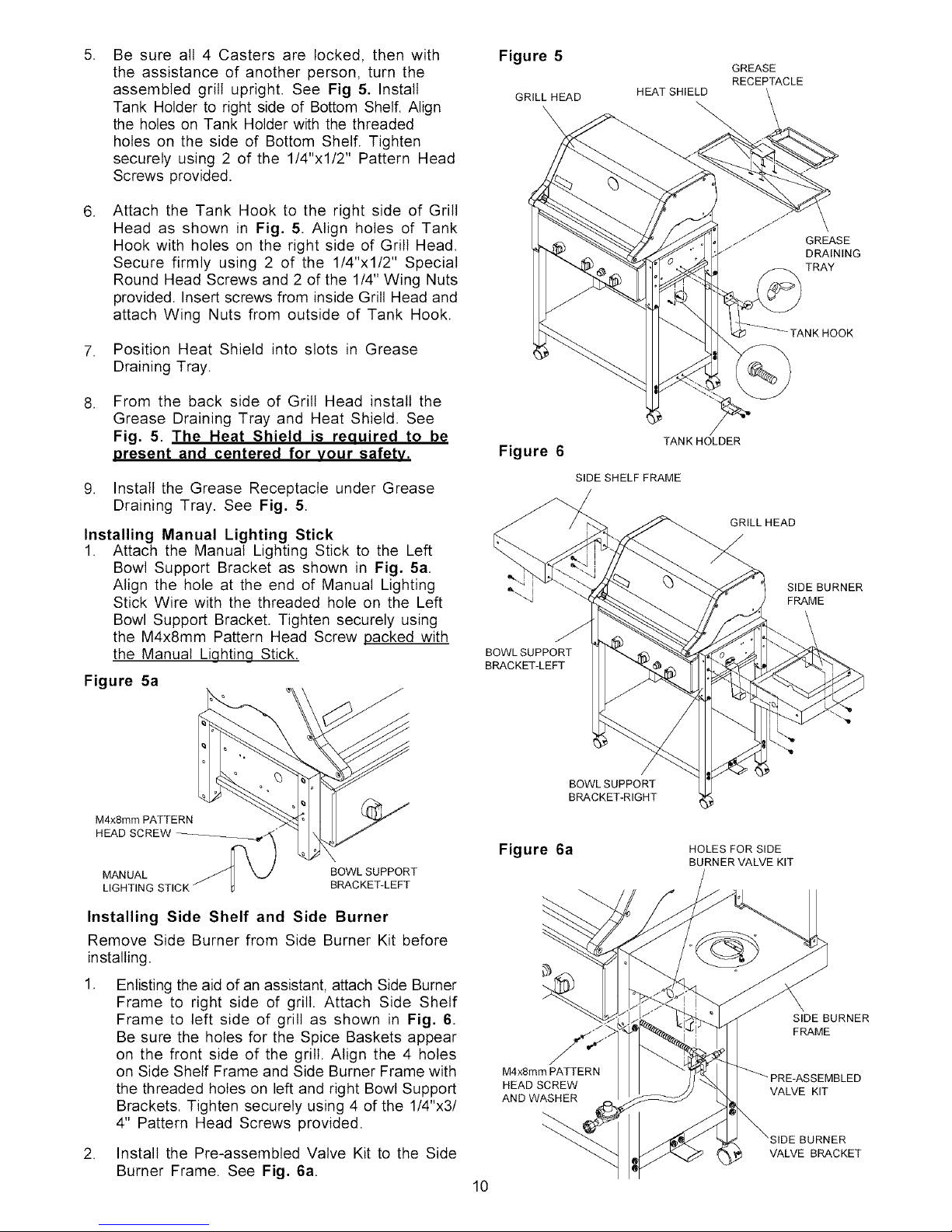
5.
Be sure all 4 Casters are locked, then with
the assistance of another person, turn the
assembled grill upright. See Fig 5. Install
Tank Holder to right side of Bottom Shelf. Align
the holes on Tank Holder with the threaded
holes on the side of Bottom Shelf. Tighten
securely using 2 of the 1/4"x1/2" Pattern Head
Screws provided.
.
Attach the Tank Hook to the right side of Grill
Head as shown in Fig. 5. Align holes of Tank
Hook with holes on the right side of Grill Head.
Secure firmly using 2 of the 1/4"x1/2" Special
Round Head Screws and 2 of the 1/4" Wing Nuts
provided. Insert screws from inside Grill Head and
attach Wing Nuts from outside of Tank Hook.
7. Position Heat Shield into slots in Grease
Draining Tray.
.
From the back side of Grill Head install the
Grease Draining Tray and Heat Shield. See
Fig. 5. The Heat Shield is reeuired to be
oresent and centered for vour safety.
9. Install the Grease Receptacle under Grease
Draining Tray. See Fig. 5.
Installing Manual Lighting Stick
1. Attach the Manual Lighting Stick to the Left
Bowl Support Bracket as shown in Fig. 5a.
Align the hole at the end of Manual Lighting
Stick Wire with the threaded hole on the Left
Bowl Support Bracket. Tighten securely using
the M4x8mm Pattern Head Screw packed with
the Manual Liqhtinq Stick.
Figure 5a
Figure 5
GRILL HEAD
Figure 6
BOWL SUPPORT
BRACKET-LEFT
HEAT SHIELD
TANK HOLDER
SIDE SHELF FRAME
GREASE
RECEPTACLE
GRILL HEAD
GREASE
DRAINING
TRAY
SIDE BURNER
FRAME
M4x8mm PATTERN
HEAD SCREW _/_"
MANUAL BOWL SUPPORT
LIGHTING BRACKET-LEFT
Installing Side Shelf and Side Burner
Remove Side Burner from Side Burner Kit before
installing.
Enlisting the aid of an assistant, attach Side Burner
Frame to right side of grill. Attach Side Shelf
Frame to left side of grill as shown in Fig. 6.
Be sure the holes for the Spice Baskets appear
on the front side of the grill. Align the 4 holes
on Side Shelf Frame and Side Burner Frame with
the threaded holes on left and right Bowl Support
Brackets. Tighten securely using 4 of the 1/4"x3/
4" Pattern Head Screws provided.
BOWL SUPPORT
BRACKET-RIGHT
Figure 6a
M4x8mm PATTERN
HEAD SCREW
AND WASHER
HOLES FOR SIDE
BURNER VALVE KIT
SIDE BURNER
FRAME
;EMBLED
VALVE KIT
IRNER
VALVE BRACKET2. Install the Pre-assembled Valve Kit to the Side
Burner Frame. See Fig. 6a.
10
 Loading...