

Kenmore 137630800 A, 137630800 Installation Instructions Manual

Installation Instructions
®
Instrucciones de Instalación
Instructions d’Installation
English / Español / Français
Kenmore
®
Front Load Washer
Lavadora a Cargo Frontal
Laveuse à Chargement Frontal
P/N 137630800 A (1308)
Sears Brands Management Corporation
Hoff man Estates, IL 60179 U.S.A.
www.kenmore.com
www.sears.com
Sears Canada Inc.
Toronto, Ontario, Canada M5B 2C3
www.sears.ca
Important Safety Instructions
WARNING
Please read all instructions before using this washer.
Recognize safety symbols, words and
labels
Safety items throughout this manual are labeled with
a WARNING or CAUTION based on the risk type as
described below:
Defi nitions
This is the safety alert symbol. It is used to alert you
to potential personal injury hazards. Obey all safety
messages that follow this symbol to avoid possible injury or
death.
DANGER
DANGER indicates an imminently hazardous situation
which, if not avoided, will result in death or serious injury.
WARNING
WARNING indicates a potentially hazardous situation
which, if not avoided, could result in death or serious
injury.
CAUTION
CAUTION indicates a potentially hazardous situation
which, if not avoided, may result in minor or moderate
injury.
IMPORTANT
IMPORTANT indicates installation, operation or
maintenance information which is important but not
hazard-related.
Table of Contents
Important Safety Instructions ............................................2-3
Installation Requirements ...................................................4-5
Washer Dimensions ................................................................6
Unpacking Washer .............................................................7-8
Installation Instructions ..................................................... 9-10
Accessories .............................................................................11
Español ................................................................................... 12
Français ..................................................................................22
Installation Checklist
Shipping Hardware
Foam shipping support (under wash tub)
removed and stored
Shipping bolts and spacers removed from rear
of appliance and stored
Hole plugs (shipped in bag in drum) installed in
holes in backsheet
Leveling
Washer is level, side-to-side and front-to-back
Cabinet is setting solid on all corners
Water Supply
Use only new hoses and verify rubber sealing
washers are installed
HOT supply is connected to HOT inlet and
COLD supply is connected to COLD inlet
HOT and COLD water supply turned on
No leaks present at water supply connections
or appliance inlet connections recheck in 24 hours
Drain
Stand pipe or wall drain height minimum 24”
Anti-siphon disc (shipped in drum) installed on
drain hose
Drain hose secured in place with cable tie
(shipped in drum)
Electrical Power
House power turned on
Washer plugged in
Final Checks
Installation Instructions
Guide
have been read thoroughly
Door locks and water enters drum when cycle
starts
and
Use and Care
2
Important Safety Requirements
NOTE
The electrical service to the washer must conform with
local codes and ordinances and the latest edition of the
National Electrical Code, ANSI/NFPA 70, or in Canada,
the Canadian electrical code C22.1 part 1.
WARNING
SUFFOCATION HAZARD
Destroy the carton and plastic bags after the washer
is unpacked. Children might use them for play. Cartons
covered with rugs, bedspreads, or plastic sheets can
become airtight chambers causing suff ocation. Place
all materials in a garbage container or make materials
inaccessible to children.
CAUTION
EXCESSIVE WEIGHT HAZARD
To avoid back or other injury, have more than one person
move or lift the washer.
WARNING
WARNING
FIRE HAZARD
For your safety the information in this manual must be
followed to minimize the risk of fi re or explosion or to
prevent property damage, personal injury or loss of life.
Do not store or use gasoline or other fl ammable vapors
and liquids in the vicinity of this or any other appliance.
IMPORTANT
The instructions in this manual and all other literature
included with this washer are not meant to cover every
possible condition and situation that may occur. Good
safe practice and caution MUST be applied when
installing, operating and maintaining any appliance.
Maximum benefi ts and enjoyment are achieved when
all the Safety and Operating Instructions are understood
and practiced as a routine with your laundering tasks.
Save these instructions
for future reference.
FIRE HAZARD
Do not stack a dryer on top of washer already installed
on pedestal. Do not stack washer on top of dryer. Do not
stack washer on top of another washer.
Pre-Installation Requirements
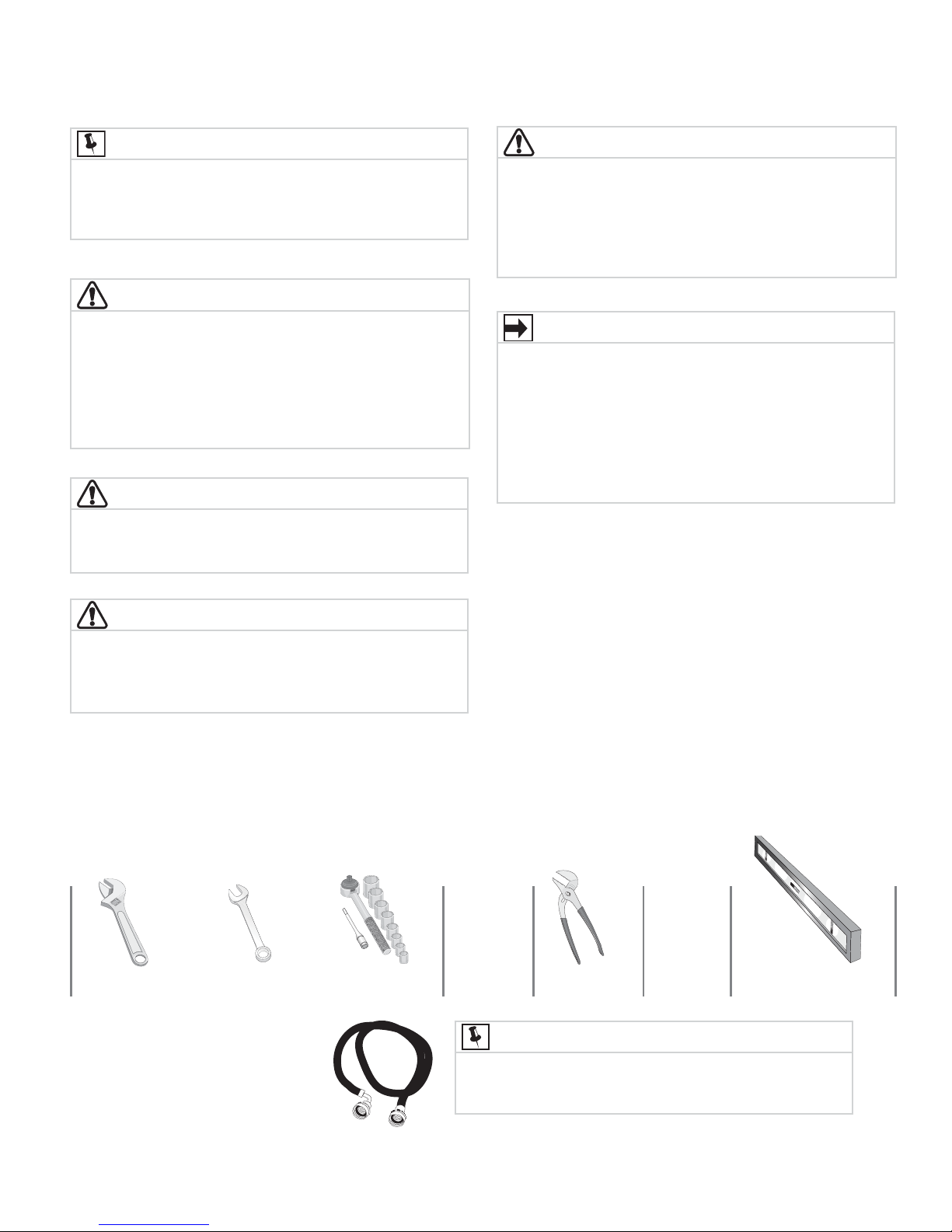
Tools and materials needed for installation:
OR OR AND AND
Adjustable
wrench
3/8” or 10 mm
box wrench
Ratchet and
socket set
Adjustable
pliers
Carpenter’s level
NOTE
Hoses are not included with washer purchase. See
“Accessories” section for various inlet hose kits to fi t your
specifi c installation.
Inlet hose (x2)
3
Grounding type
ll receptacle
wer cord with
3-prong grgr
ounded plug
Do not,
under
y cir
cumstances,
cut,
removeve,
or b
ypass the
ounding pr
ong.
Installation Requirements
Electrical system requirements
CIRCUIT - Individual, properly polarized and grounded 15
amp. branch circuit fused with 15 amp. time delay fuse
or circuit breaker.
POWER SUPPLY - 2 wire, with ground, 120 volt single
phase, 60 Hz, Alternating Current.
NOTE
Because of potentially inconsistent voltage capabilities,
the use of this washer with power created by gas
powered generators, solar powered generators, wind
powered generators or any other generator other than
the local utility company is not recommended.
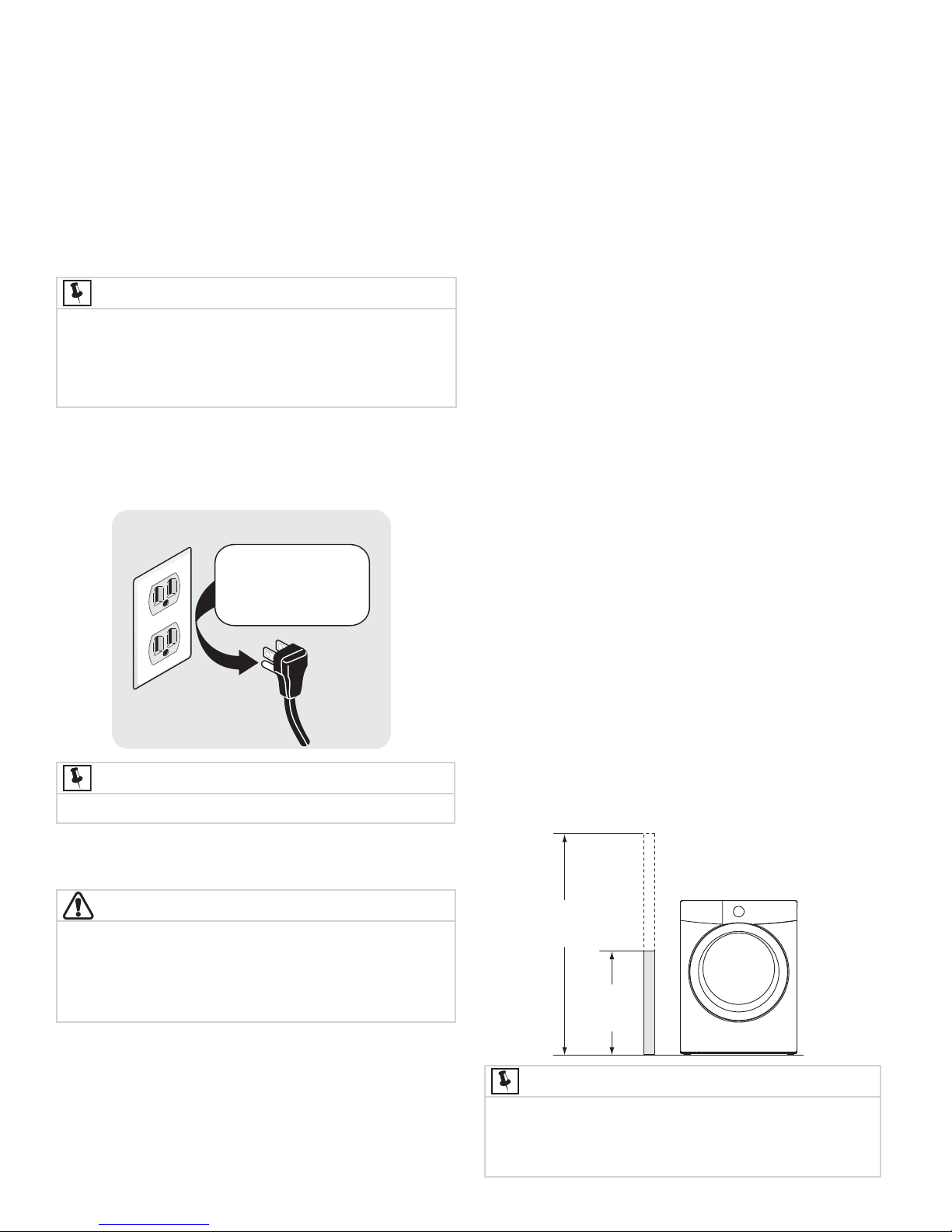
OUTLET RECEPTACLE - Properly grounded 3-prong
receptacle to be located so the power supply cord is
accessible when the washer is in an installed position.
Grounding type
wawall receptacl
Do not,
under
anany cir
cumstances,
cut,
remo
or b
ypass th
grgrounding pr
ong.
2 Since your washer is equipped with a power supply
cord having an equipment-grounding conductor
and a grounding plug, the plug MUST be plugged
into an appropriate, copper wired receptacle that is
properly installed and grounded in accordance with
all local codes and ordinances or in the absence
of local codes, with the National Electrical Codes,
ANSI/NFPA 70 (latest edition). If in doubt, call
a licensed electrician. DO NOT cut off or alter
the grounding prong on the power supply cord. In
situations where a two-slot receptacle is present,
it is the owner’s responsibility to have a licensed
electrician replace it with a properly grounded three
prong grounding type receptacle.
Water supply requirements
Hot and cold water faucets MUST be installed within hose
length of your washer’s water inlet. The faucets MUST be
3/4 inch (1.9 cm) and have threading for laundry hose
connection. Water pressure MUST be between 30 and 120
psi. Pressure diff erence between hot and cold cannot be
more than 10 psi. Your water department can advise you of
your water pressure.
PoPower cord with
3-prong
ounded plug
NOTE
GFI (Ground Fault Interrupter) receptacle is not required.
Ground requirements
WARNING
ELECTRICAL SHOCK HAZARD
Improper connection of the equipment grounding
conductor can result in a risk of electrical shock. Check
with a licensed electrician if you are in doubt as to
whether the appliance is properly grounded.
1 The washer MUST be grounded. In the event of
malfunction or breakdown, grounding will reduce the
risk of electrical shock by providing a path of least
resistance for electrical current.
Drain system requirements
1 Drain capable of eliminating 17 gals (64.3 L) per
minute.
2 A standpipe diameter of 1-1/4 in. (3.18 cm)
minimum.
3 The standpipe height above the fl oor should be:
Minimum height: 24 in. (61 cm)
Maximum height: 96 in. (244 cm)
96”
(244cm)
max.
24”
(61cm)
min.
NOTE
Drain hose attached to the washer can reach a 74 in.
(188 cm) high standpipe. For higher standpipe, use hose
P/N 137098000, available from Sears Parts & Repair.
Call 1-800-4-MY-HOME.
4
Clearance requirements
IMPORTANT
DO NOT INSTALL YOUR WASHER:
1 In an area exposed to dripping water or outside
weather conditions. The ambient temperature
should never be below 60° F (15.6° C) to maximize
detergent eff ectiveness.
2 In an area (garage or garage-type building)
where gasoline or other fl ammables (including
automobiles) are kept or stored.
3 On carpet. Floor MUST be solid with a maximum
slope of 1 inch (2.54 cm). To minimize vibration
or movement, reinforcement of the fl oor may be
necessary.
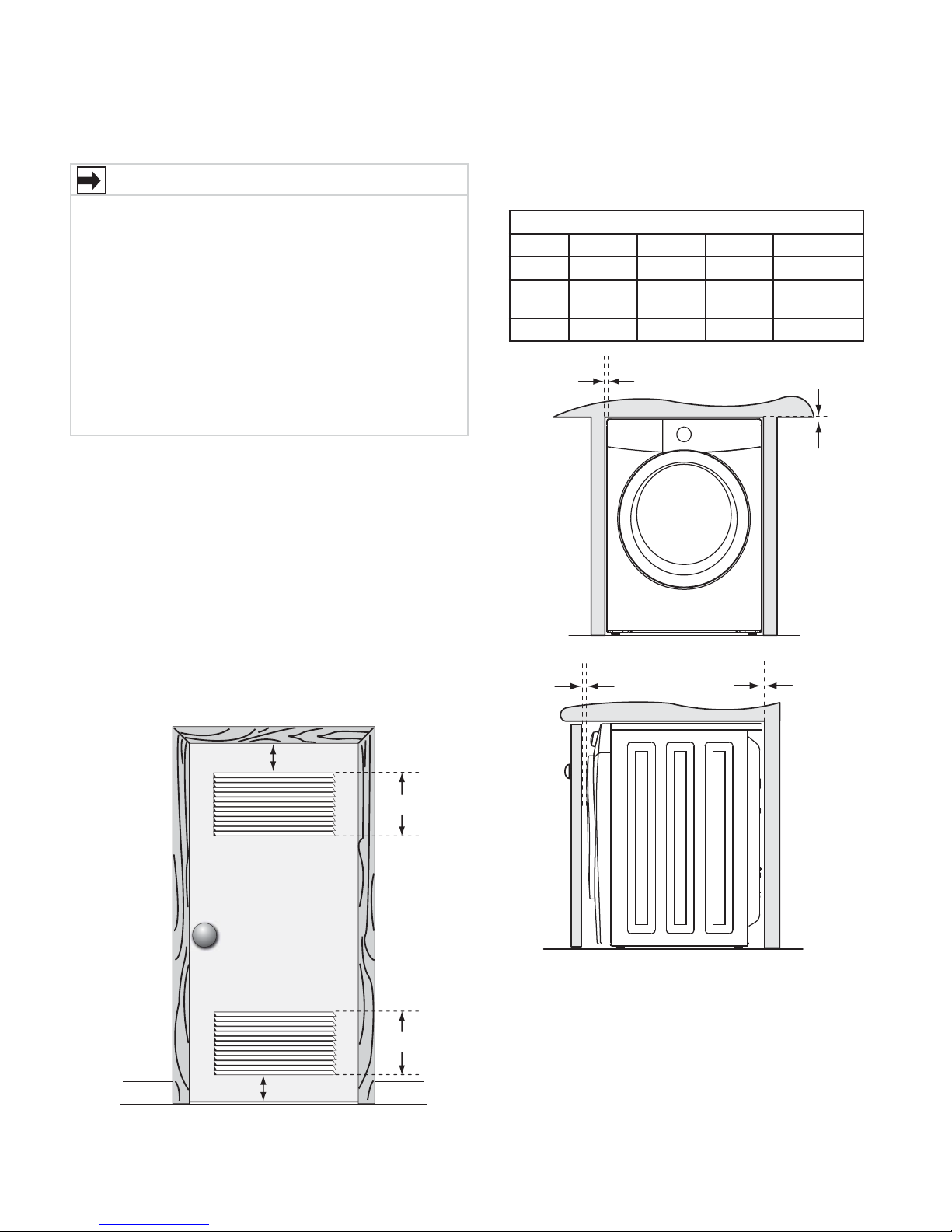
Installation in a Recess or Closet
If washer and dryer are installed in the same closet, door
ventilation is required: A minimum of 120 square inches
(774.2 cm²) of opening, equally divided at the top and
bottom of the door, is required. Louvered openings should
be located 3 inches (7.6 cm) from bottom and top of door.
Air openings are required to be unobstructed when a door
is installed. A louvered door with equivalent air openings
for the full length of the door is acceptable.
Installation Requirements
MINIMUM INSTALLATION CLEARANCES - Inches (cm)
SIDES REAR TOP FRONT
Alcove 0” (0 cm) 0” (0 cm)* 0” (0 cm) n/a
Under-
Counter
Closet 0” (0 cm) 0” (0 cm)* 0” (0 cm) 1” (2.5 cm)
0” (0 cm) 0” (0 cm)* 0” (0 cm) n/a
0”
(0cm)
1”
(2.5cm)
0”
(0cm)
0”
(0cm)
3”
(7.6cm)
3”
(7.6cm)
closet door
60 sq. in.
(387.1cm²)
60 sq. in.
(387.1cm²)
5
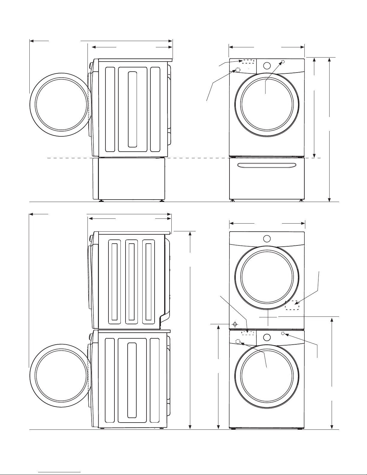
Washer Dimensions
51.4” (131cm)*
to clear open door
freestand
washer on fl oor
fl oor line
washer mounted on
optional pedestal
fl oor line
30.3” (77cm)*
to front of closed door
water supply
connection on
rear of unit
drain hose on
rear of unit
27.0”
(68.5 cm)
36.0”
(91.5 cm)
power cord on
1
rear of unit
2
51.25”
(130 cm)
51.4” (131cm)*
to clear open door
30.3” (77cm)*
to front of closed door
71.5”
(182 cm)
water supply
connection on
rear of unit
gas supply
pipe on rear
of gas unit
37”
(94 cm)
27.0”
(68.5 cm)
drain hose on
rear of unit
2
electrical
supply on
rear of unit
centerline
height for
rear vent
power cord on
rear of unit
1
3
fl oor line
*Connection of water inlet hose on steam dryer adds 3/4 in. (2 cm) to installation depth.
1
Power supply cord length on washer approximately 60 inches (152.5 cm).
2
Drain hose length on washer approximately 59 inches (150 cm).
3
Power supply cord length on gas dryer approximately 60 inches (152.5 cm).
39”
(99 cm)
6
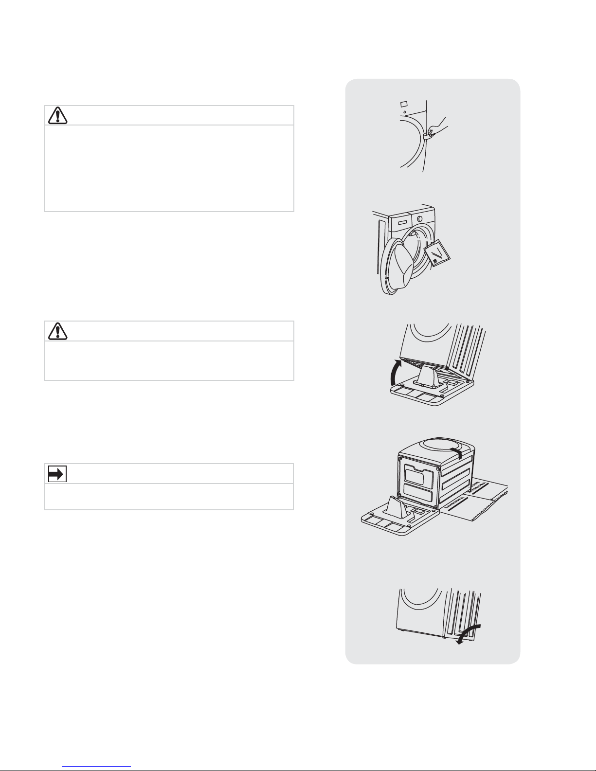
Removing foam packaging
WARNING
SUFFOCATION HAZARD
Destroy the carton and plastic bags after the washer
is unpacked. Children might use them for play. Cartons
covered with rugs, bedspreads, or plastic sheets can
become airtight chambers causing suff ocation. Place
all materials in a garbage container or make materials
inaccessible to children.
1 Temporarily remove door tape.
2 Open washer door and remove everything from the
drum.
3 Close door and reapply door tape.
4
Using a rug, blanket or piece of cardboard to protect
the fl oor, carefully lay the washer on its back.
Unpacking Washer
CAUTION
EXCESSIVE WEIGHT HAZARD
To avoid back or other injury, have more than one person
move or lift the washer.
5 Remove styrofoam base and shipping plug and set
them aside.
6 Carefully return the washer to an upright position.
7 Carefully move the washer to within 4 feet (1 m) of
its fi nal location.
IMPORTANT
Save styrofoam base and shipping plug for use to help
prevent washer damage during any future moves.
7
Unpacking Washer
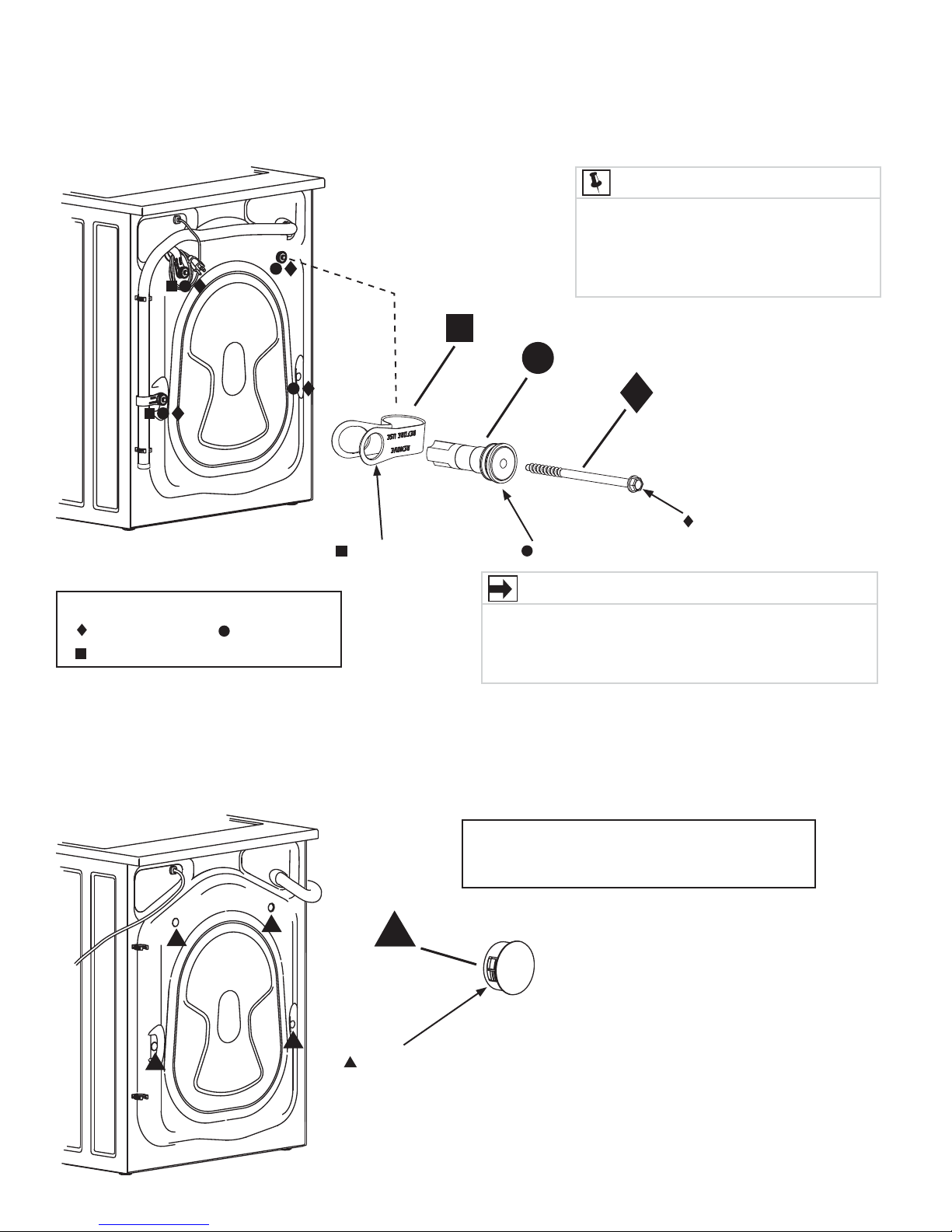
Removing shipping hardware
NOTE
Rubber expansion material on spacers
may need time to relax before they can
be easily pulled through shipping hole. You
may have to exert some force to pull out if
spacer material has not yet fully relaxed.
x 2
x 4
x 4
4 BOLTS
Remove all of the following:
4 BOLTS
2 P CLAMPS
4 SPACERS
Installing hole plugs
2 P CLAMPS
x 4
4 SPACERS
IMPORTANT
Save all shipping bolts and spacers for future use. If the
washer is to be transported at a later date, the shipping
hardware must be reinstalled to help prevent shipping
damage.
Locate 4 hole plugs in the small bag supplied
with washer instruction guides. Insert them in the
holes in washer back panel.
4 HOLE PLUGS
(IN BAG)
8
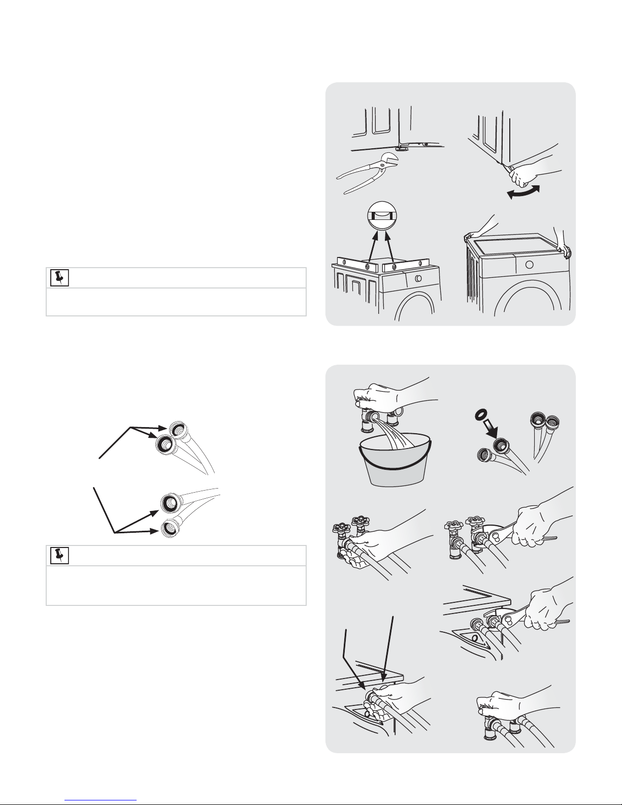
Leveling your washer
Excessive noise and vibration can be prevented by
properly leveling the washer.
1 For free standing installation and with the washer
within 4 feet (1 m) of its fi nal location, place a level
on top of the washer.
2 Use adjustable pliers to adjust the leveling legs so
the washer is level front-to-rear and side-to-side,
and stable corner-to-corner.
3 Press down on alternate corners and sides and feel
for the slightest movement. Adjust the appropriate
leg(s) so the washer sits solidly on the fl oor on ALL
four legs. Keep the leveling leg extension at a
minimum for best performance of the washer.
NOTE
For pedestal installations, see additional installation
instructions included with the pedestal.
Installation Instructions
a
c
b
raise
lower
d
Connecting inlet water
1 Run some water from the hot and cold faucets to
fl ush the water lines and remove particles that might
clog the water valve screens and to determine which
faucet is hot and which is cold supply.
RUBBER WASHERS
MUST BE PRESENT
USE ONLY
NEW HOSES
NOTE
Hoses are not included with washer purchase. See
“Accessories” section for various inlet hose kits to fi t your
specifi c installation.
2 Connect the HOT inlet hose to the HOT inlet
connection on the washer and the COLD inlet
hose to the COLD inlet connection on the washer.
Tighten by hand until snug. Then tighten each supply
connection another 2/3 turn with pliers. Do not cross
thread or over-tighten these connections.
3 Connect the HOT inlet hose to the HOT water supply
and the COLD inlet hose to the COLD water supply.
Tighten by hand until snug. Then tighten each supply
connection another 2/3 turn with pliers. Do not
bend, kink or pinch water inlet hoses.
4 Turn on the water and check for leaks.
a
HOT
c
COLD
b
d
f
e
g
9
type
Grounding
receptacle
ll
wer cord
with 3-prong
ounded plug
Do not, under any circumstances,
cut, remove, or bypass the
grounding prong.
Installation Instructions
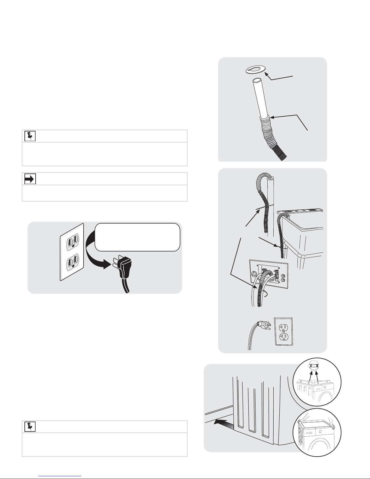
Connecting drain and electrical
1 Locate the anti-siphon ring shipped with your washer.
Place it over the end of the drain hose and slide it past
the fi rst ring of “accordion” ribs.
2 Form a “U” shape on the end of the drain hose with the
hose pointed toward the drain. Place the formed end in
a laundry tub or a standpipe and secure the drain hose
with the cable tie (provided in the enclosure package)
to the standpipe, inlet hose, laundry tub, etc. so the hose
does not pull out from the force of the water.
ANTI-SIPHON
DISC
NOTE
The standpipe inside diameter must be 1-1/4” (3.2 cm)
minimum. There must be an air gap around the drain hose in
the standpipe. A snug hose fi t can cause a siphoning action.
IMPORTANT
Check to ensure the power is off at a circuit breaker/fuse
box before plugging the power cord into an outlet.
3 Plug the power cord into a grounded outlet.
Do not, under any circumstances,
Grounding
type
wawall
receptacle
4 Turn on the power at a circuit breaker/fuse box.
5 Carefully slide the washer to its fi nal position. Recheck
for level and rock corners for stability. Remove and
discard door tape.
6 Read the
Use & Care Guide
contains valuable and helpful information that will save
you time and money.
7 Run the washer through a complete cycle, checking for
water leaks and proper operation.
8 If you have any questions during initial operation, please
review the “Avoid Service Checklist” in your
Guide
before calling for service.
9 Place these instructions in a location near the washer for
future reference.
NOTE
A wiring diagram and technical data sheet are located
under the washer top panel, on top of the detergent
dispenser housing.
cut, remove, or bypass the
grounding prong.
provided with the washer. It
SLIDE DISC
TO HERE
CABLE TIE
PoPower cord
with 3-prong
grgrounded plug
Use & Care
10
 Loading...