


OWNER'S MANUAL
SEWING MACHINE
MODEL 1340 / 1345 / 1350 / 1355 / 1358
1561/1595
69548
.
KNOWING YOUR SEWING MACHINE
Machine identification .............................................. 2 -3
Parts list................................................................ 4- 5
Setting up your machine ................. :........................... 6
Spool pins, Foot control, Light/power switch
Installing extension table ............................................. 6
Winding bobbin ........................................................ 7
Removing bobbin case from shuttle ............................... 8
Inserting bobbin into bobbin case .................................. 9
Inserting bobbin case into shuttle .................................. 9
Threading top th read .................................................. 10
Picking up bobbin thread ............................................. 11
CONTROLS
Thread tension control ................................................ 12
Stitch selector, Stitch length control .............................. 13
Reverse stitch control, Pressure regulator ........................ 14
Seam guides, Presser foot lever, Feed dog control ............. 15
ACCESSORIES
Needles ................................................................... 16
Placement of needle ................................................... 16
Needle, thread and fabric chart ..................................... 17
Feed cover plate, Presser feet ...................................... 18
CARING FOR THE MACHINE
Cleaning feed dogs and shuttle ..................................... 19
Oiling ................................................................ 20 - 21
Changing light bulb .................................................... 21
CHECKING PERFORMANCE PROBLEMS ............. 22-23
2_
STARTING TO SEW ............................................... 24
Straight stitching ................................................. 25 - 27
Fastening a seam, Turning a square corner,
Removing fabric, Top stitching, Darning,
Temporary sewing by machine, Zipper application-Cording
Zigzag stitching ................................................... 28 - 30
Checking thread tension, Overcasting, Satin stitching,
Bar tacking, Appliqueing, Button sewing
Blind Hemming ................................................... ;..... 31
Mending and overcast stitching (three-step zigzag) ............ 32
Shell stitching ........................................................... 33
Box stitch ................................................................ 34
Stretch stitches ................................................... 35- 38
Adjusting stitch length, Straight stretch stitch,
Rick-rack stretch, Smocking stretch, Overcast stretch,
Serging {or pine leaf) stretch, Elastic stretch
Where to use which stretch stitch: A check-chart .............. 39
Buttonhole making ............................................... 40 - 47
Free-arm sewing ........................................................ 48
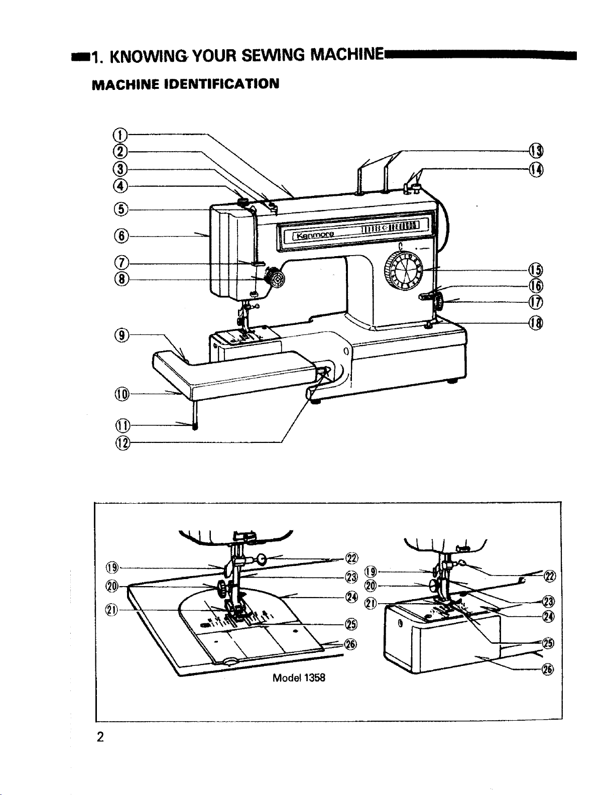
==1. KNOWING YOUR SEWING MACHINE
MACHINE IDENTIFICATION
O
®.
®
®
IIII IIIIII IIIII
@
@
®
@
@
@
Model 1358
2
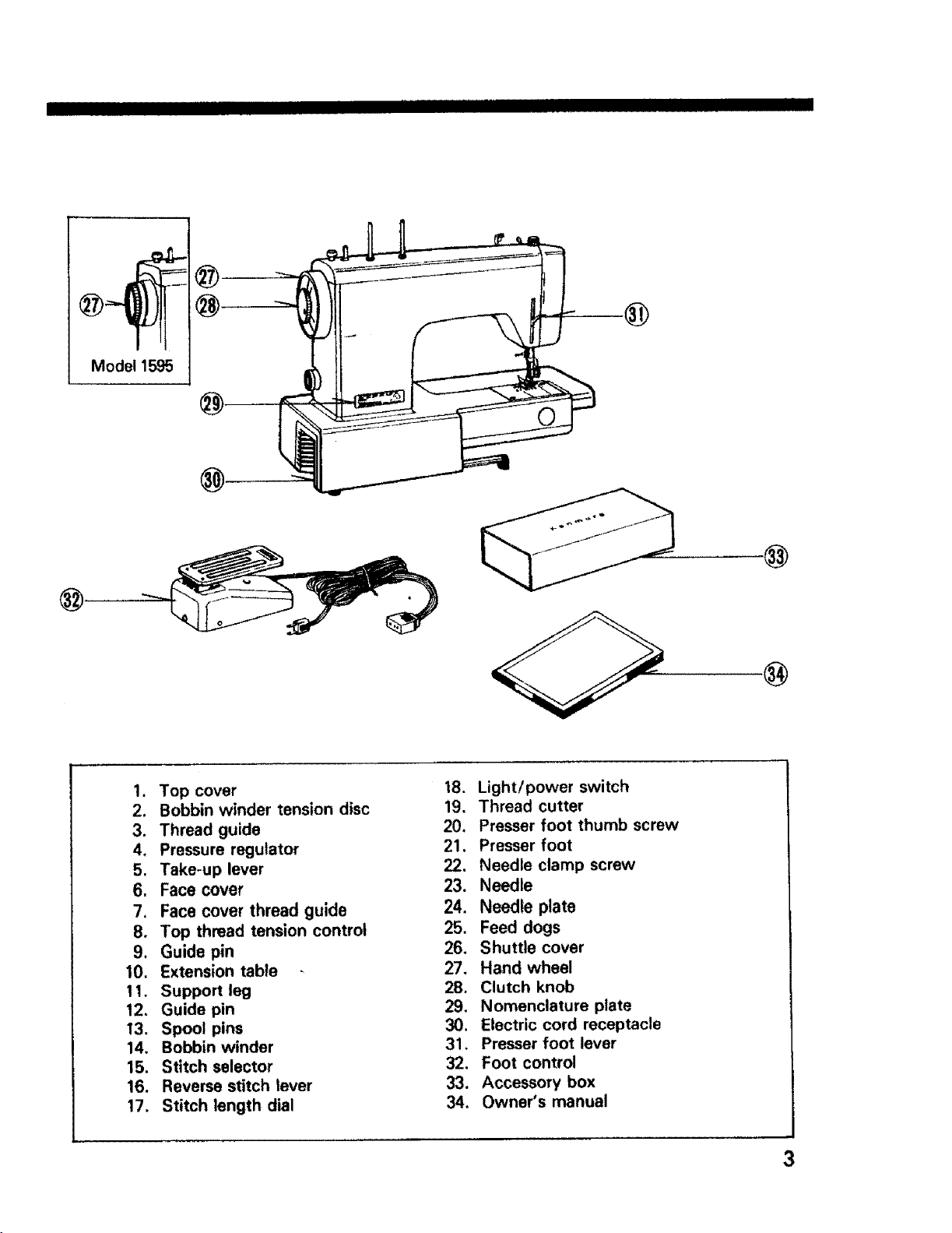
Model 1595
I IIIIIIIII IIIII II I IIIII IIII III
®
1. Top cover
2. Bobbin winder tension disc
3. Thread guide
4, Pressure regulator
5. Take-up lever
6. Face cover
7, Face cover thread guide
8, Top thread tension control
9. Guide pin
10, Extension table
11. Support leg
12, Guide pin
13. Spool pins
14. Bobbin winder
15. Stitch selector
16. Reverse stitch lever
17. Stitch length dial
.@
18. Light/power switch
19. Thread cutter
20. Presser foot thumb screw
21. Presser foot
_. Needle clamp screw
23. Needle
24, Needle plate
25. Feed dogs
26. Shuttle cover
27. Hand wheel
28. Clutch knob
29. Nomenclature plate
30, Electric cord receptacle
31. Presser foot lever
32. Foot control
33. Accessory box
34. Owner's manual
I
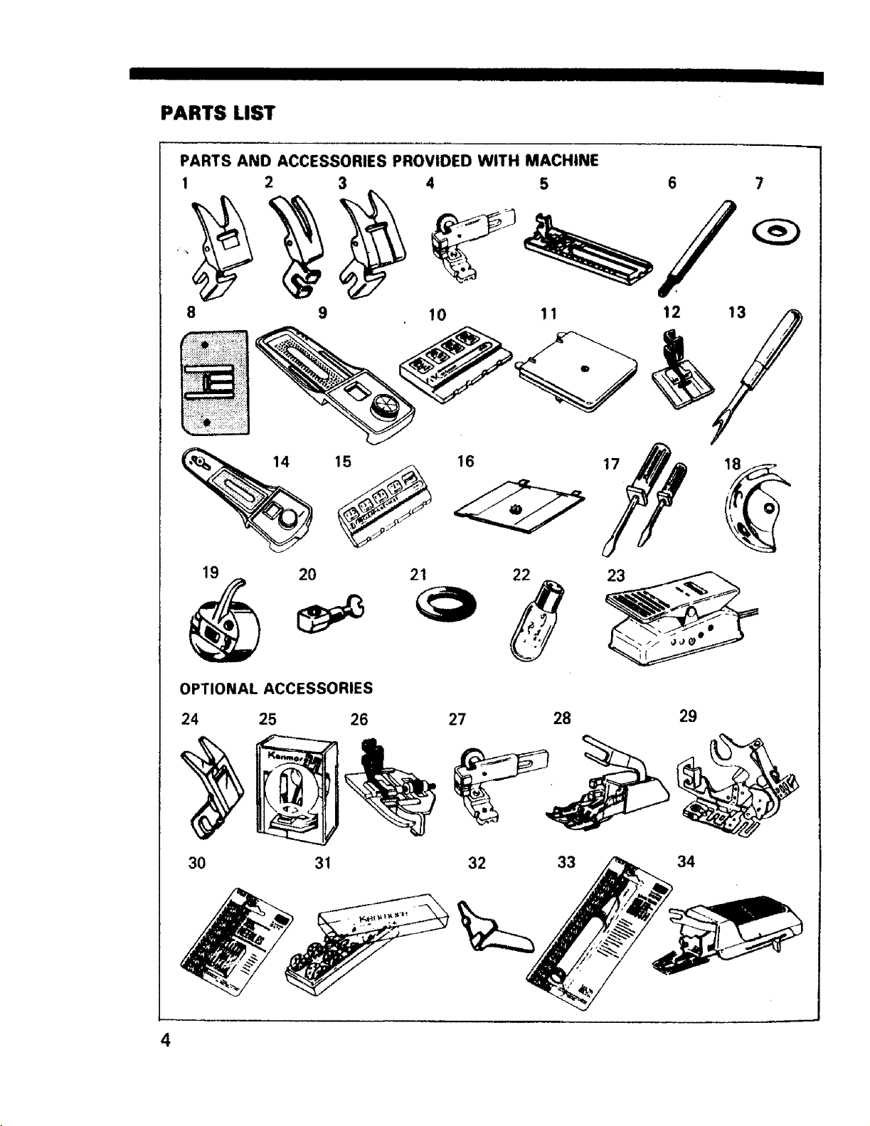
PARTS LIST
PARTS AND ACCESSORIES PROVIDED WITH MACHINE
1
2 4
IIIIIII
6
8
15
19
OPTIONAL ACCESSORIES
24 25 26
20 21
10
16
27 28
11
12 13
23
29
30 31
4
32 33
34
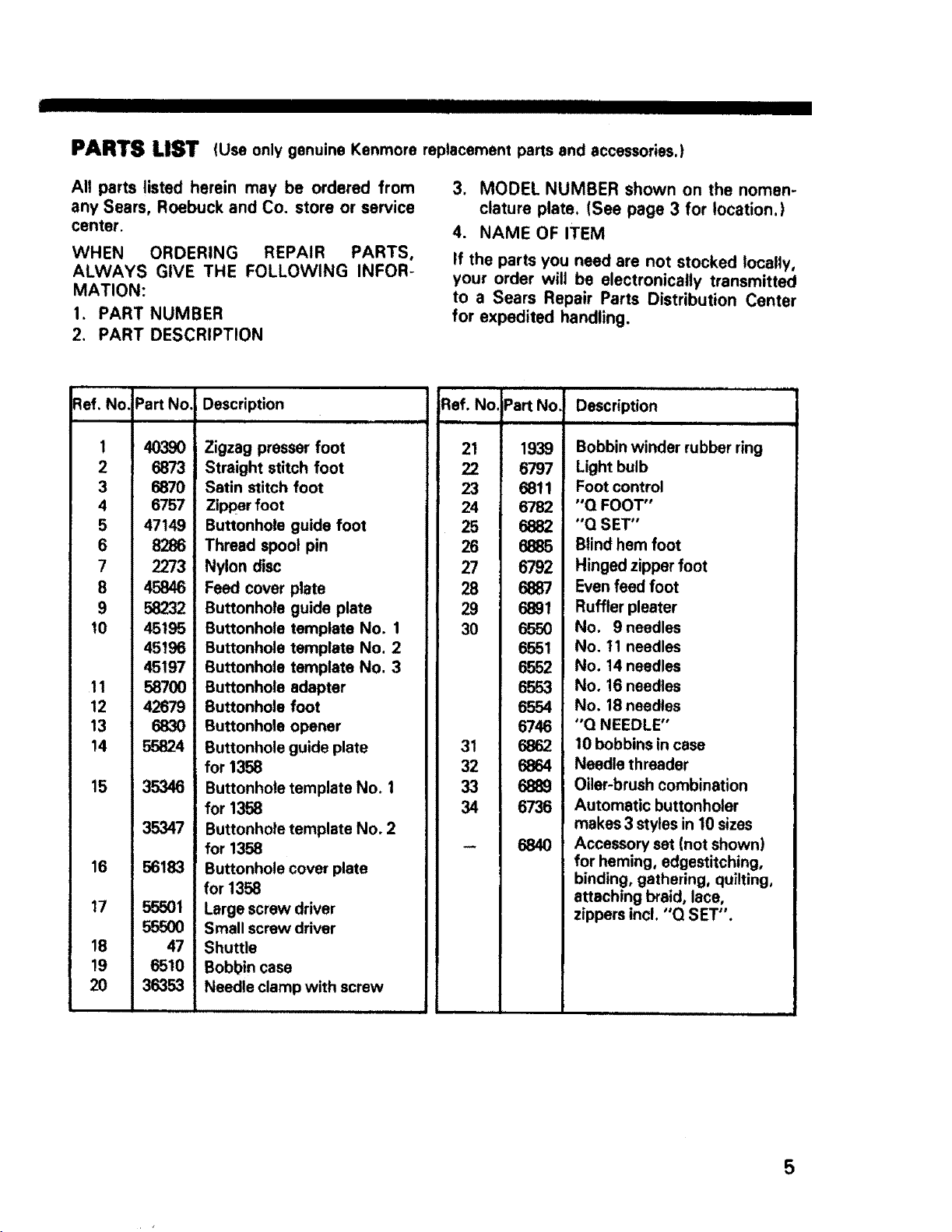
PARTS LIST (Useonly genuine Kenmore replacement parts and accessories,)
All parts listed herein may be ordered from
any Sears, Roebuck and Co. store or service
center.
WHEN ORDERING REPAIR PARTS,
ALWAYS GIVE THE FOLLOWING INFOR-
MATION:
1. PART NUMBER
2. PART DESCRIPTION
_lef. NO,
11
10
12
13
14
15
16
17
18
19
2O
2
3
4
5
6
7
8
9
1
Part No.
40390
6873
6870
6757
47149
8286
2273
45846
58232
45195
45196
45197
58700
42679
6830
55824
35346
35347
68183
55501
47
6510
36353
Description
Zigzag presser foot
Straight stitch foot
Satin stitch foot
Zipper foot
Buttonhole guide foot
Thread spool pin
Nylon disc
Feed cover plate
Buttonhole guide plate
Buttonhole template No. 1
Buttonhole template No. 2
Buttonhole template No. 3
Buttonhole adapter
Buttonhole foot
Buttonhole opener
Buttonhole guide plate
for 1358
Buttonhole template No. 1
for 1358
Buttonhole template No. 2
for 1368
Buttonhole cover plate
for 1358
Large screw driver
Small screw driver
Shuttle
Bobbin case
Needle clamp with screw
3. MODEL NUMBER shown on the nomen-
clature plate. (See page 3 for location.)
4. NAME OF ITEM
If the parts you need are not stocked locally,
your order will be electronically transmitted
to a Sears Repair Parts Distribution Center
for expedited handling.
RefoNo.
Part No. Description
21
23
24
25
26
27
28
29
30
31
32
33
34
1939 Bobbin winder rubber ring
6797 Light bulb
6811 Foot control
6782 "Q FOOT"
6882 "Q SET"
6885 Blind hem foot
6792 Hinged zipper foot
6887 Even feed foot
6891 Ruffler pleater
6550 No. 9 needles
6551 No. 11 needles
6552 No. 14 needles
6553 No. 16 needles
6554 No. 18 needles
6746 "Q NEEDLE"
6862 10 bobbins in case
6864 Needle threader
6889 Oiler-brush combination
6736 Automatic buttonholer
6840 Accessory set (not shown)
iiiiii i ii i i
makes 3 styles in 10 sizes
for heming, edgestitching,
binding, gathering, quilting,
attaching braid, lace,
zippers incl. "Q SET".
5
• I IIIIIIIIIIIIIIIIIIIII J
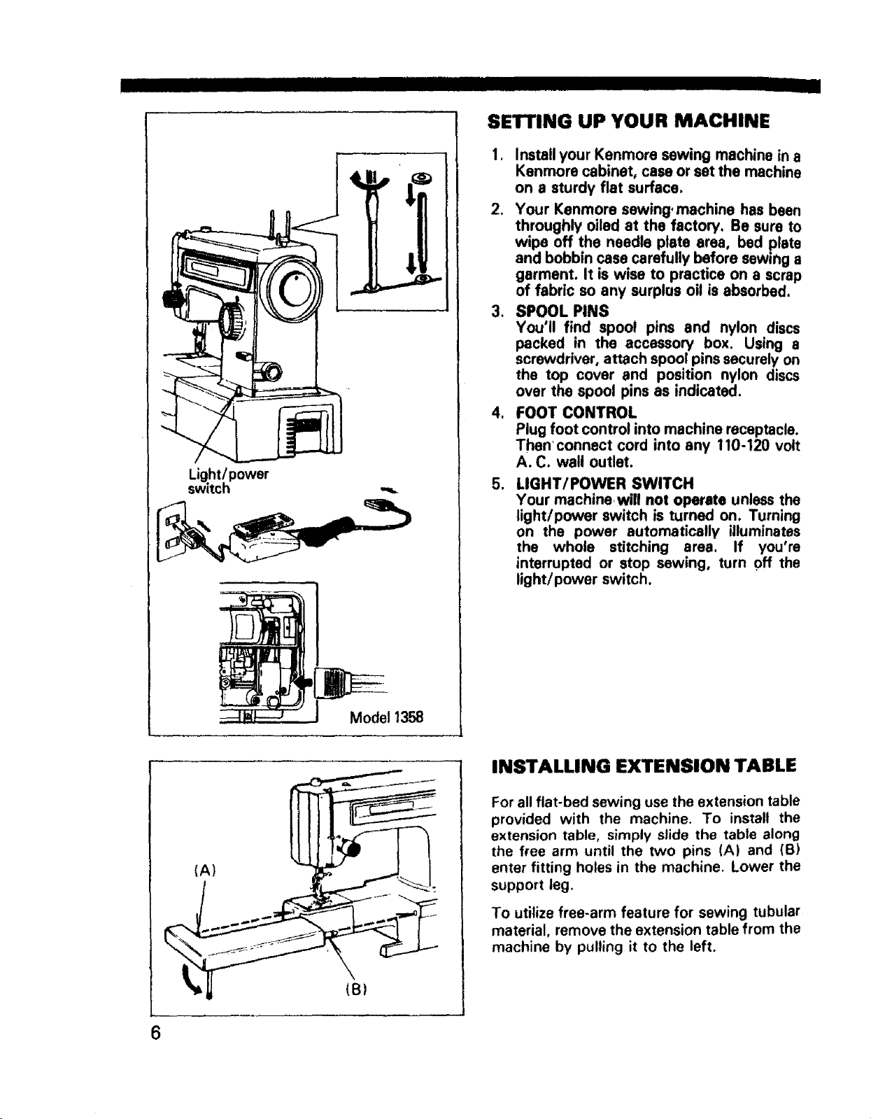
SETTING UP YOUR MACHINE
1. Install your Kenmore sewing machine in a
Kenmore cabinet, case or set the machine
on a sturdy flat surface.
2. Your Kenmore sewing, machine has been
throughly oiled at the factory. Be sure to
wipe off the needle plate area, bed plate
and bobbin case carefully before sewing a
garment, It is wise to practice on a scrap
of fabric so any surplus oil is absorbed,
3. SPOOL PINS
You'll find spool pins and nylon discs
packed in the accessory box. Using a
screwdriver, attach spool pins securely on
the top cover and position nylon discs
over the spool pins as indicated.
4. FOOT CONTROL
Plug foot control into machine receptacle.
Then connect cord into any 110-120 volt
A. C. wall outlet,
Light(power
switch
5. LIGHT/POWER SWITCH
Your machine will not operate unless the
light/power switch is turned on. Turning
on the power automatically illuminates
the whole stitching area. If you're
interrupted or stop sewing, turn off the
light/power switch.
(A)
Model 1358
INSTALLING EXTENSION TABLE
For all fiat-bed sewing use the extension table
provided with the machine. To install the
extension table, simply slide the table along
the free arm until the two pins (A) and (B)
enter fitting holes in the machine, Lower the
support leg.
To utilize free-arm feature for sewing tubular
material, remove the extension table from the
machine by pulling it to the left.
II IH II H IIIIII I I IIIIIIIIIIIIIIIIIIIIIIIIHIIIIIHII
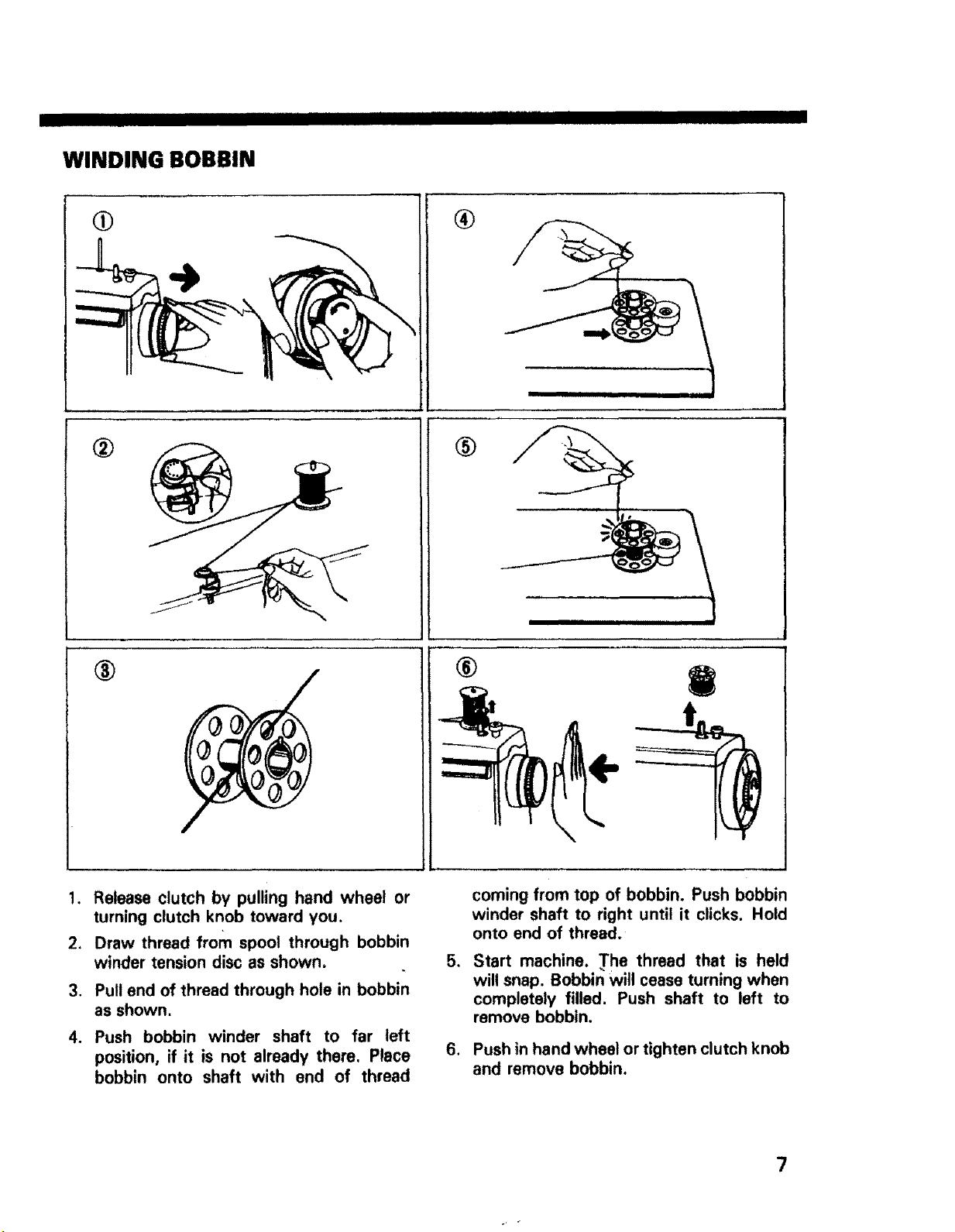
WINDING BOBBIN
O
®
®
®
i I i t
®
!. Release clutch by pulling hand wheel or
turning clutch knob toward you.
2. Draw thread from spool through bobbin
winder tension disc as shown.
3. Pull end of thread through hole in bobbin
as shown.
4. Push bobbin winder shaft to far left
position, if it is not already them. Place
bobbin onto shaft with end of thread
coming from top of bobbin. Push bobbin
winder shaft to right until it clicks. Hold
onto end of thread.
5.
Start machine. The thread that is held
will snap. Bobbin will cease turning when
completely filled. Push shaft to left to
remove bobbin.
,
Push in hand wheel or tighten clutch knob
and remove bobbin.
7
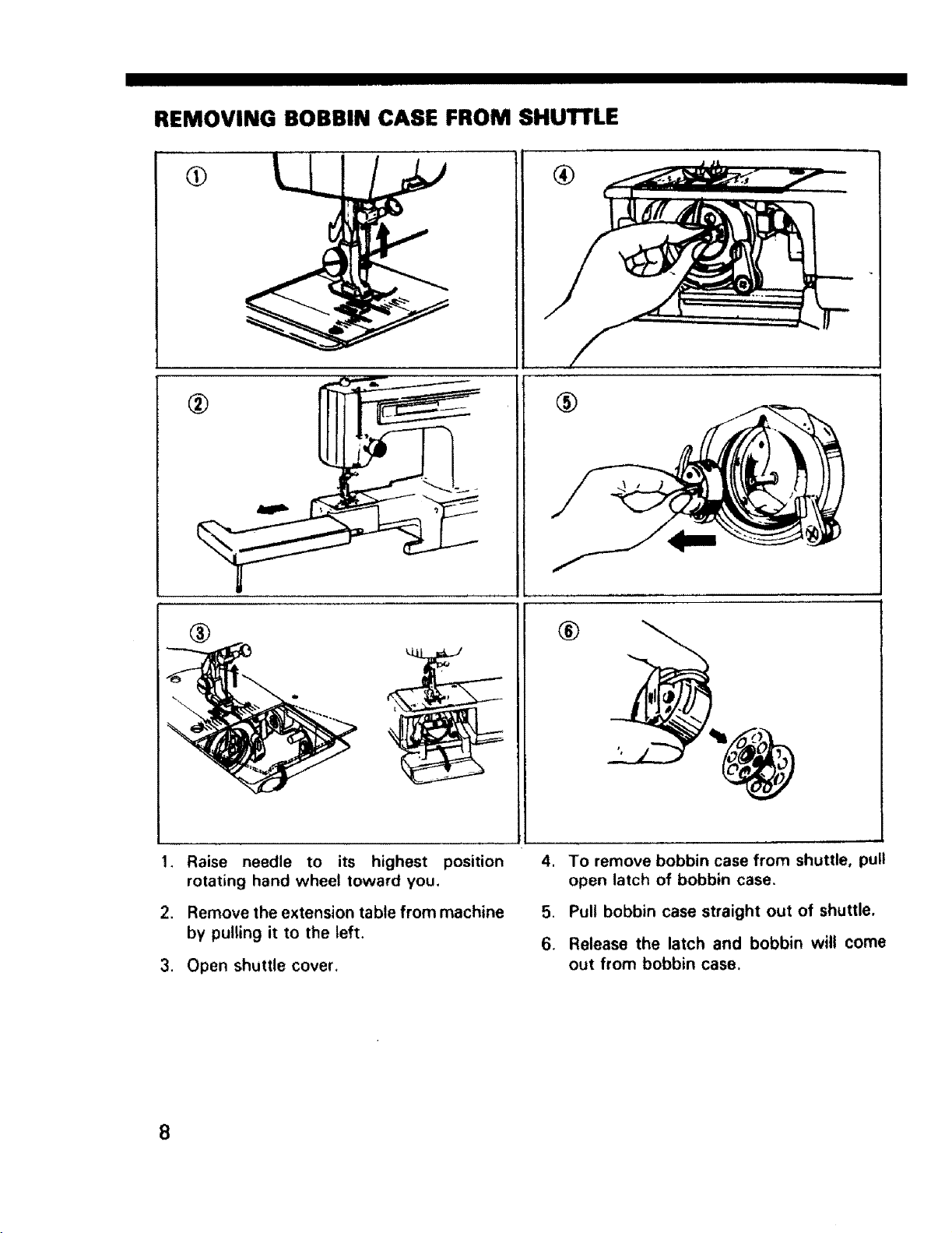
REMOVING BOBBIN CASE FROM SHUTTLE
®
®
1, Raise needle to its highest position 4.
rotating hand wheel toward you.
2. Remove the extension table from machine 5.
by pulling it to the left.
3. Open shuttle cover.
®
To remove bobbin case from shuttle, pull
open latch of bobbin case.
Pull bobbin case straight out of shuttle.
6.
Release the latch and bobbin wilt come
out from bobbin case.
8
I IIII IMH
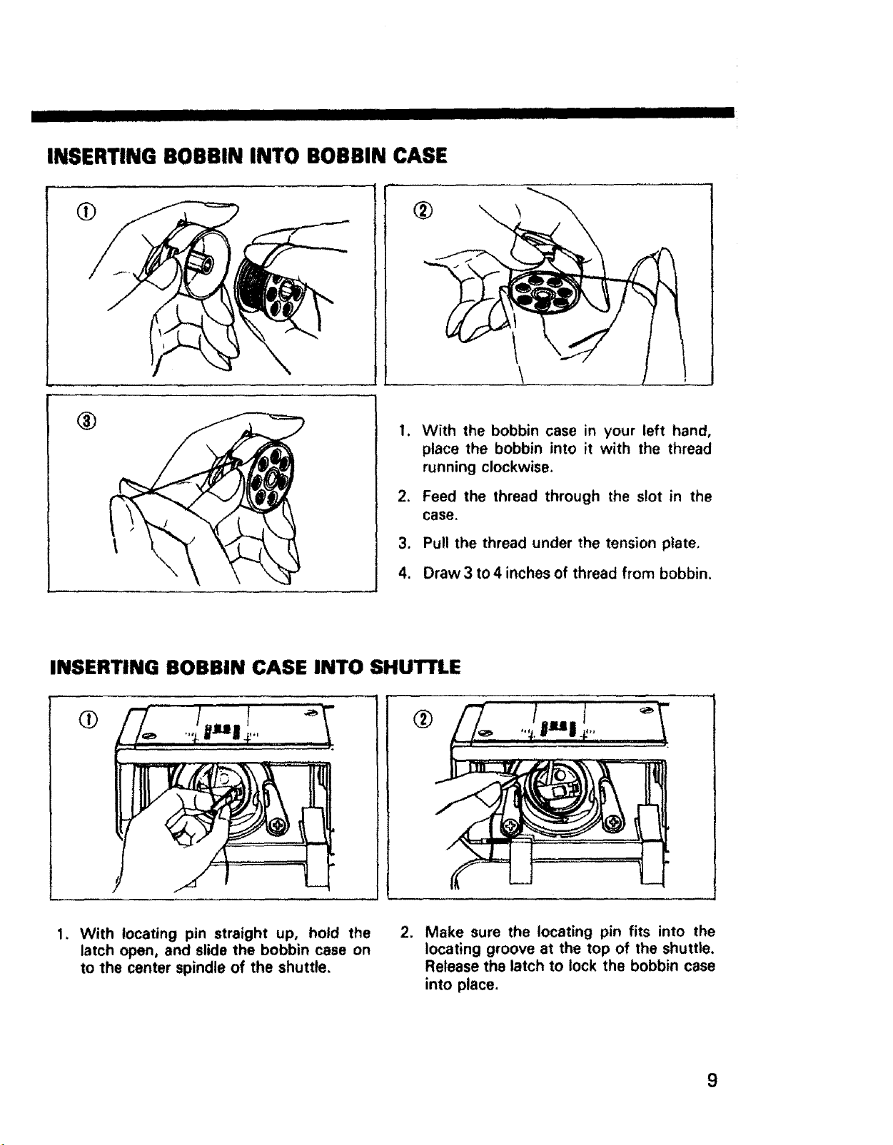
INSERTING BOBBIN INTO BOBBIN CASE
I HI I II
®
,
With the bobbin case in your left hand,
place the bobbin into it with the thread
running clockwise.
*
Feed the thread through the slot in the
case.
3.
Pull the thread under the tension plate.
4.
Draw 3 to 4 inches of thread from bobbin,
INSERTING BOBBIN CASE INTO SHUTTLE
i
With locating pin straight up, hold the
latch open, and slide the bobbin case on
to the center spindle of the shuttle.
.
Make sure the locating pin fits into the
locating groove at the top of the shuttle.
Release the latch to lock the bobbin case
into place.
9
IIIIIIII IIIII IIIII I IIII IIIIIIIIIIIIIIIII
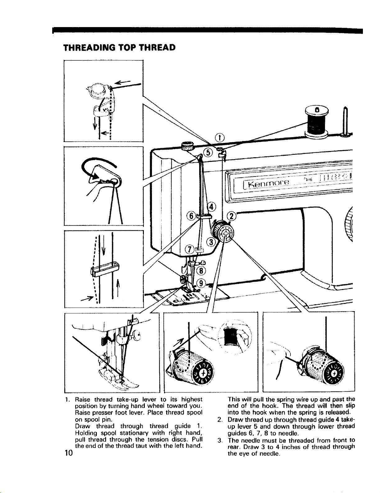
THREADING TOP THREAD
...........
Raise thread take-up lever to its highest
position by turning hand wheel toward you.
Raise presser foot lever. Place thread spool
on spool pin,
Draw thread through thread guide 1.
Holding spool stationary with right hand,
pull thread through the tension discs. Pull
the end of the thread taut with the left hand.
10
This will pull the spring wire up and past the
end of the hook. The thread will then slip
into the hook when the spring is released.
2_
Draw thread up through thread guide 4 take-
up lever 5 and down through lower thread
guides 6, 7, 8 to needle.
3_
The needle must be threaded from front to
rear, Draw 3 to 4 inches of thread through
the eye of needle.
.... IIIIIIIIIIIIII I IIIIIIIIIHIIIIIIIIIIIIIIIIIIIIIII I II I
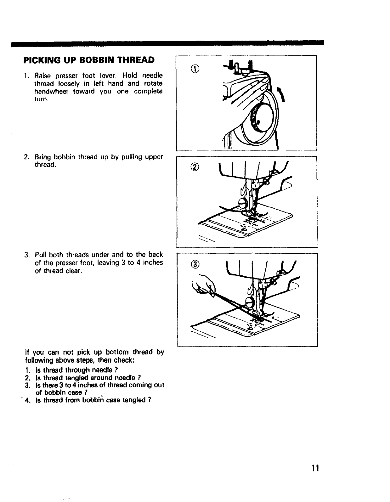
PICKING UP BOBBIN THREAD
1. Raise presser foot lever. Hold needle
thread loosely in left hand and rotate
handwheel toward you one complete
turn.
.
Bring bobbin thread up by pulling upper
thread.
®
3. Pull both threads under and to the back
of the presser foot, leaving 3 to 4 inches
of thread clear.
If you can not pick up bottom thread by
following above steps, then check:
1. Is thread through needle ?
2. Is thread tangled around needle ?
3. Is there 3 to 4 inches of thread coming out
of bobbin case ?
4. Is thread from bobbin case tangled ?
®
11
j IIIIII UlIHHHIIIIIII IIIIII
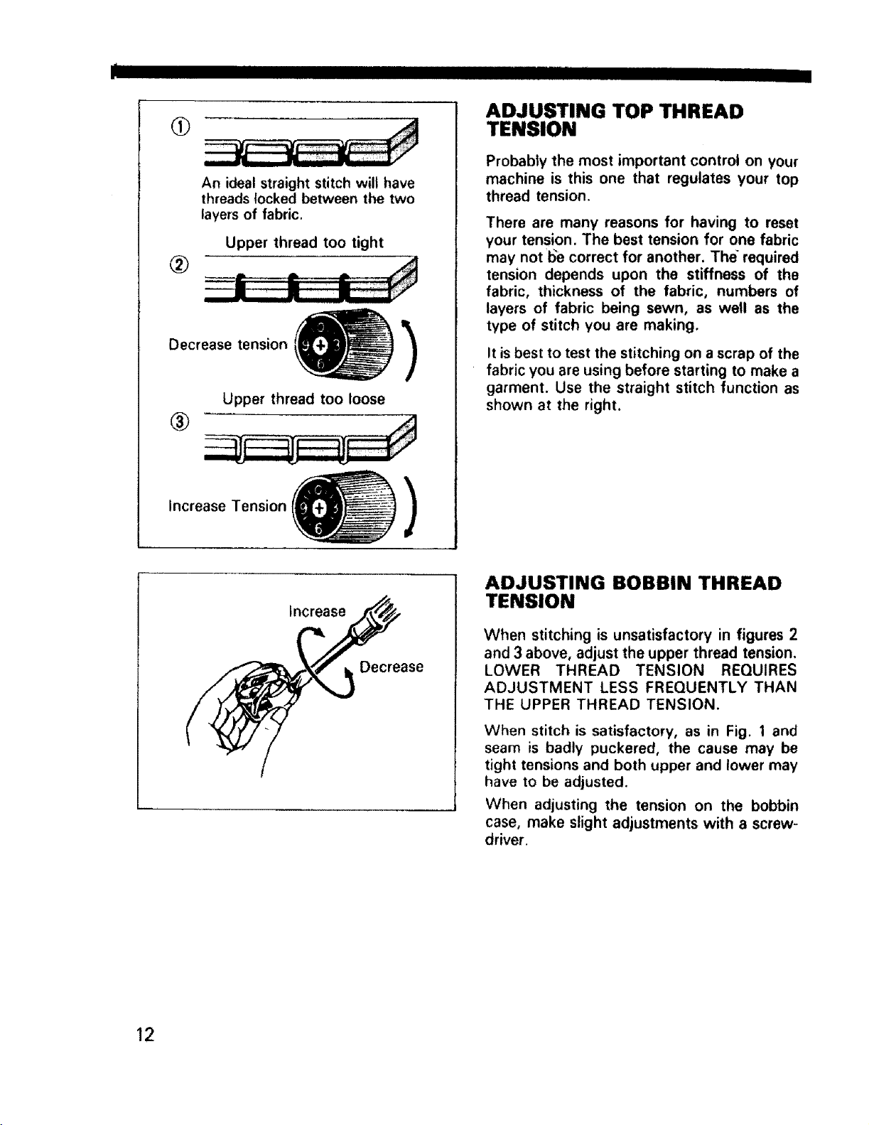
ADJUSTING TOP THREAD
q>
An ideal straight stitch will have
threads locked between the two
layers of fabric.
Upper thread too tight
®
Decrease tension
Upper thread too loose
TENSION
Probably the most important control on your
machine is this one that regulates your top
thread tension.
There are many reasons for having to reset
your tension. The best tension for one fabric
may not I_e correct for another. The required
tension depends upon the stiffness of the
fabric, thickness of the fabric, numbers of
layers of fabric being sewn, as well as the
type of stitch you are making.
It is best to test the stitching on a scrap of the
fabric you are using before starting to make a
garment. Use the straight stitch function as
shown at the right.
®
Increase Tension
Increase
)
Decrease
ADJUSTING BOBBIN THREAD
TENSION
When stitching is unsatisfactory in figures 2
and 3 above, adjust the upper thread tension.
LOWER THREAD TENSION REQUIRES
ADJUSTMENT LESS FREQUENTLY THAN
THE UPPER THREAD TENSION.
When stitch is satisfactory, as in Fig. 1 and
seam is badly puckered, the cause may be
tight tensions and both upper and lower may
have to be adjusted.
When adjusting the tension on the bobbin
case, make slight adjustments with a screw-
driver.
12
I I ! III I
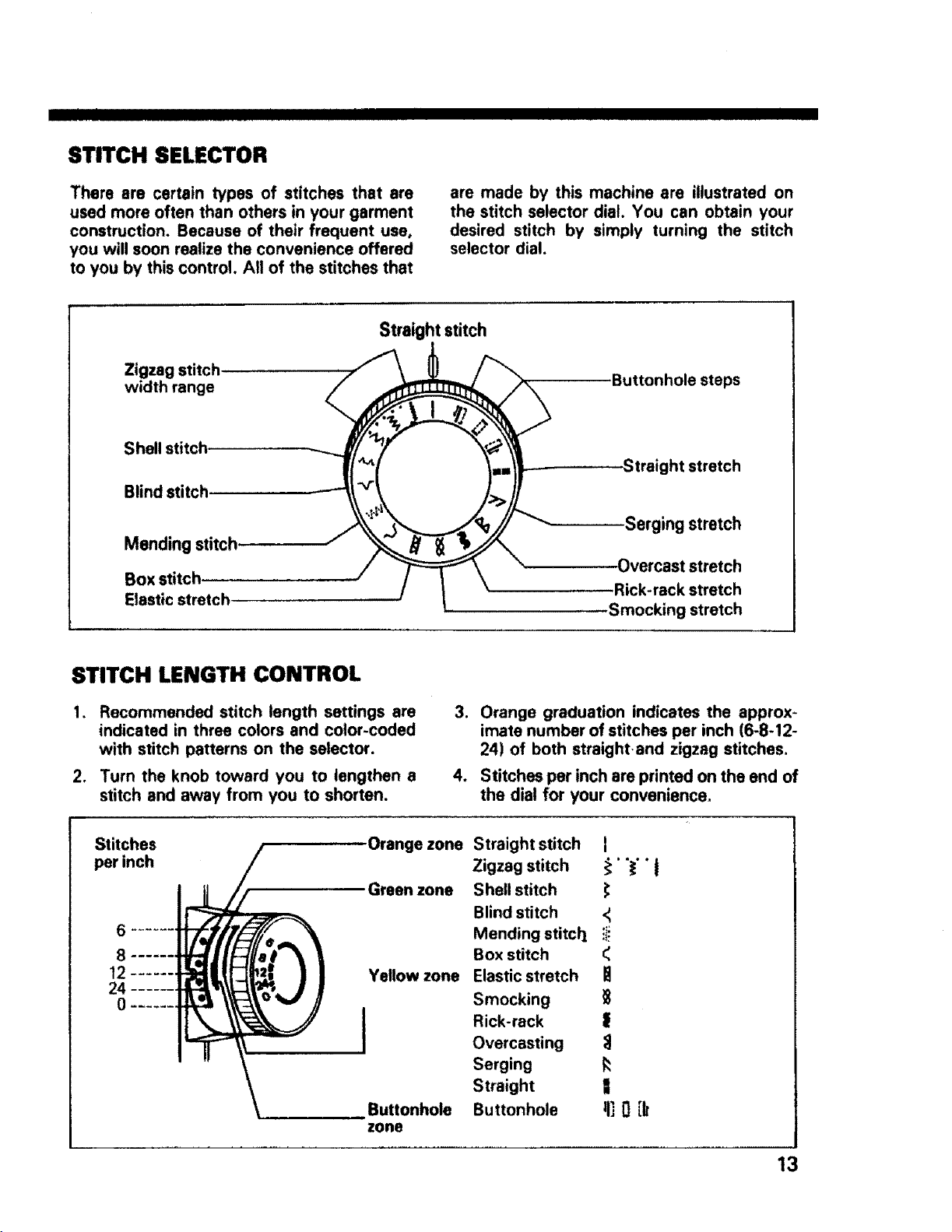
STITCH SELECTOR
There are certain types of stitches that are
used more often than others in your garment
construction. Because of their frequent use,
you will soon realize the convenience offered
to you by this control. All of the stitches that
Straight stitch
Zigzag stitch.
width range
Shell stitch
Blind 1
Mending stitch
Elastic stretch
are made by this machine are illustrated on
the stitch selector dial. You can obtain your
desired stitch by simply turning the stitch
selector dial.
Buttonhole steps
Straight stretch
Serging stretch
stretch
Rick-rack stretch
Smocking stretch
STITCH LENGTH CONTROL
.
Recommended stitch length settings are
indicated in three colors and color-coded
with stitch patterns on the selector.
,
Turn the knob toward you to lengthen a
stitch and away from you to shorten.
Stitches Orange zone
per inch
Green zone
6
8
t2 Yellow zone
24
° I
Buttonhole
zone
3. Orange graduation indicates the approx-
imate number of stitches per inch (6-8-12-
24) of both straight.and zigzag stitches.
4. Stitches per inch are printed on the end of
the dial for your convenience,
Straight stitch [
Zigzag stitch i' '_'" J
Shell stitch
Blind stitch <_
Mending stitcll iii
Box stitch
Elastic stretch
Smocking
Rick-rack |
Overcasting :_
Serging _:
Straight |
Buttonhole II] 0 [k
13
I I ]11[11!11111111IIII
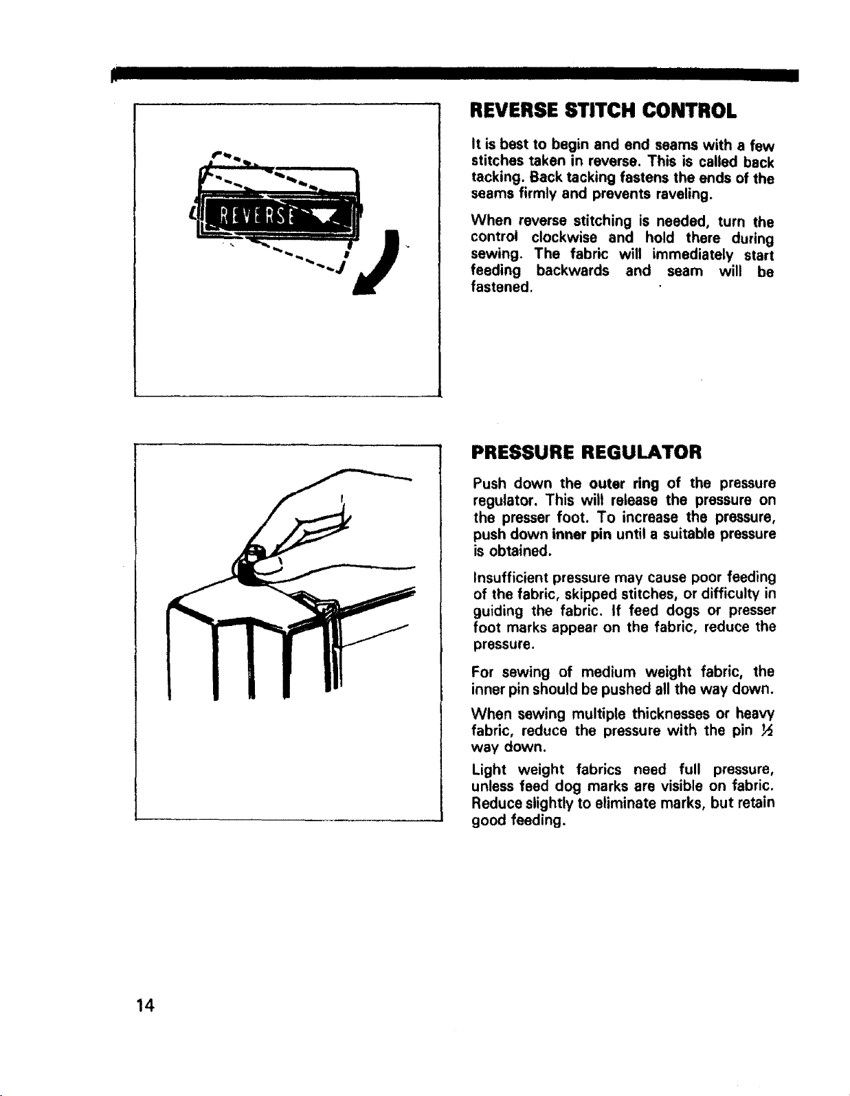
REVERSE STITCH CONTROL
It is best to begin and end seams with a few
stitches taken in reverse. This is called back
tacking. Back tacking fastens the ends of the
seams firmly and prevents raveling.
When reverse stitching is needed, turn the
control clockwise and hold there during
sewing. The fabric will immediately start
J
feeding backwards and seam will be
fastened.
PRESSURE REGULATOR
Push down the outer ring of the pressure
regulator. This will release the pressure on
the presser foot. To increase the pressure,
push down inner pin until a suitable pressure
is obtained.
insufficient pressure may cause poor feeding
of the fabric, skipped stitches, or difficulty in
guiding the fabric. If feed dogs or presser
foot marks appear on the fabric, reduce the
pressure.
For sewing of medium weight fabric, the
inner pin should be pushed all the way down.
When sewing multiple thicknesses or heavy
fabric, reduce the pressure with the pin ½
way down.
Light weight fabrics need full pressure,
unless feed dog marks are visible on fabric.
Reduce slightly to eliminate marks, but retain
good feeding.
14
 Loading...