

Kenmore 119.16148110 Use & Care Manual

Use & Care Guide
Manual de Uso y Cuidado
English / Español
Models/Modelos: 119.16148110
Kenmore®
Liquid Propane Gas Grill
Parilla a gas de propane liquido
P/N MCDKPTA000
Sears Brands Management Corporation
Hoffman Estates, IL 60179 U.S.A
www.kenmore.com
www.sears.com
1
Hardware Pack Listing
A
G
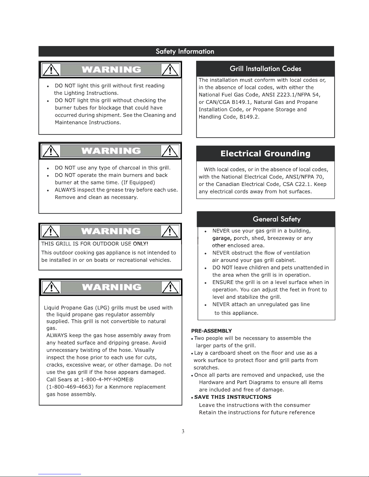
Phillips Head Bolt M6x25mm
Qty: 2pcs
Part No.:MCDKY14000
Flat Head Bolt M6x25mm
Qty: 4pcs
Part No. MCDKY15000
Step Bolt M6
Qty: 4pcs
Part No.:MCDKY16000
B
C
D
Grill Transport Handle Heat Shield
Qty: 2pcs
Part No.:FP00 27
H
Phillips Head Screwdriver
Qty: 1 pc
Part No.:MCDKY20000
I
Battery Size AA
Qty: 1pc
J
Propane Tank Support Chain Hook
Flat Head Bolt M6x12mm
Qty: 8pcs
Part No.:MCDKY17000
Phillips Head Bolt M6x10mm
Qty: 9pcs
Part No.:MCDKY18000
Washer Head Bolt M4x10mm
Qty: 14pcs
Part No.:MCDKY19000
E
F
Qty: 1 pc
Part No.:S4061-000B-001
Propane Tank Support Chain
Qty: 1 pc
Part No.:SE0232-001
4
K

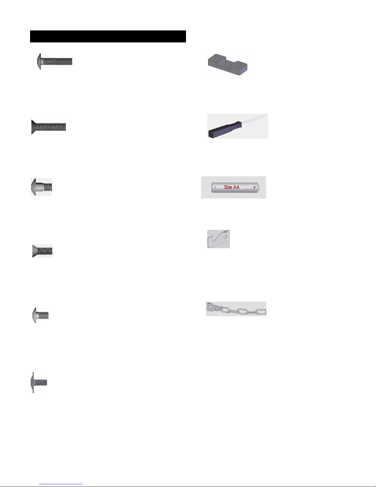
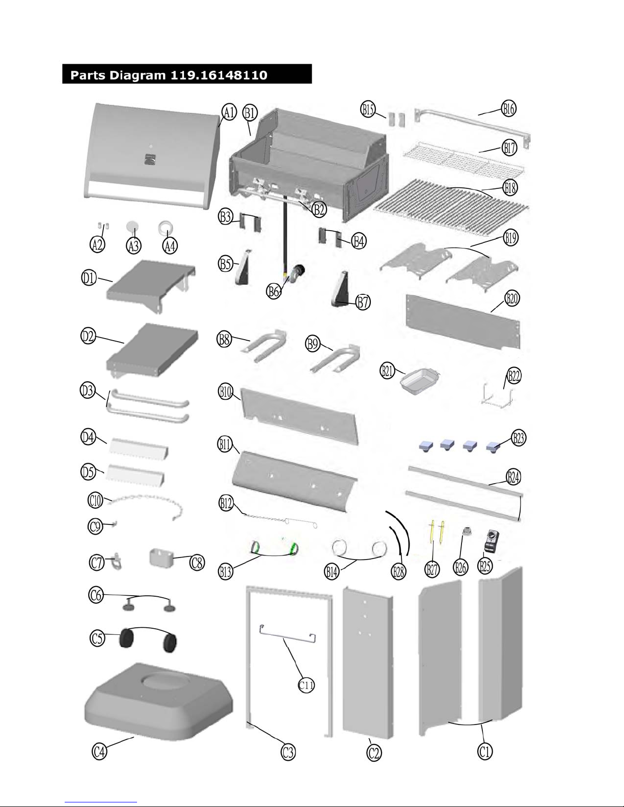
Parts List 119.16148110
Key Qty Part No.
A1 1 HCDKCVA038 Hood Assembly
A2 2 *ASMA0014-03 Hood Bolt
Description
A3 1 SE0208 Thermometer
A4 1 CA0045-002 Thermometer Seat
B1 1 HCDKBDA048 Firebox Assembly
B2 1 SC0094
B3 2 S7007-026D-018
B4 2 S7007-026D-017
B5 1 S1036-026D-016 Control Panel Left Support
B6 1 MCDKADD000 Regulator and Hose Assembly
B7 1 S1036-026D-017 Control Panel Right Support
B8 1 SD0048Z-K00A "U" Burner - Left
B9 1
SD0049Z-K00A "U" Burner - Right
B10 1 *ASMB0081-02 Firebox Front Shield Panel
B11 1 *ASMB0083-01 Control Panel
B12 1 SE0282-001 Manual Igniter Stick
B13 2 PLABS0090-001 Control Knob
B14 2 FA0121-001
B15 2
FP0027 Grill Transport Handle Heat Insulator
B16 1 *ASMB0081-04
B17 1 SE0280-012
B18 2 SE0281-012
B19 2 S1007-012E-014Z Heat Diffuser
Gas Manifold Assembly
Shelf Right-Front Left-Back Support
Shelf Left-Front Right-Back Support
Control Knob Seat
Grill Transport Handle
Warming Rack
Cooking Grate
B20 1 S1017-026D-012 Firebox Rear Shield Panel
B21 1 MCCCYPD125 Grease Pan
B22 1 MCDKYPB000
B23 4 FE0025M
B24 1
*ASMB0081-06 Firebox Assembly Support
B25 1 MCDKFID001 Electric Igniter
B26 1 MCDKFID002 Electric Igniter Button
B27 2 SE9009 Electrode
Grease Pan Bracket
Hood Bumper
5
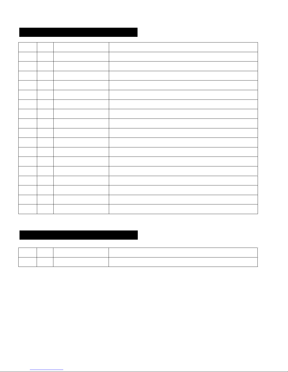
Parts List 119.16148110
Key Qty Part No. Description
B28
C1 2 HCDKFRA038 Cabinet Side Panel
*ASMB0081-07 Electronic Igniter Wire Set
1
C2 1 *ASMC0083-03 Cabinet Front Panel
C3 1 *ASMC0084-02 Cabinet Frame Assembly
C4 1 HCDKBTA048 Cabinet Bottom Panel
C5 2 FE0080 Caster
C6 2 FE0154N Adjustable Foot
C7 1 S8015-000B-001 Bottle Opener
C8 1 S8014-000A-007 Cap Catcher
C9 1 S4061-000B-001 Propane Tank Support Chain Hook
C10 1 SE0232-001 Propane Tank Support Chain
C11 1 MCDKFRH015 LP Tank Bracket
D1 1 S7002-026D-022 Left Shelf Assembly
D2 1 S7002-026D-023 Right Shelf Assembly
D3 2 *ASME0024-03 Shelf Handle
D4 1 *ASME0083-01 Shelf Left Control Panel
D5 1 *ASME0083-02 Shelf Right Control Panel
Not Pictured
N/A 1 PCDKPA0000 Hardware Pack
N/A 1 MCDKPTA000 Manual
If you are missing hardware or have damaged parts after unpacking grill, call 1-800-933-0527 for replacement.
To order replacement parts after using grill, call 1-800-4-MY-HOME®.
6
7
7
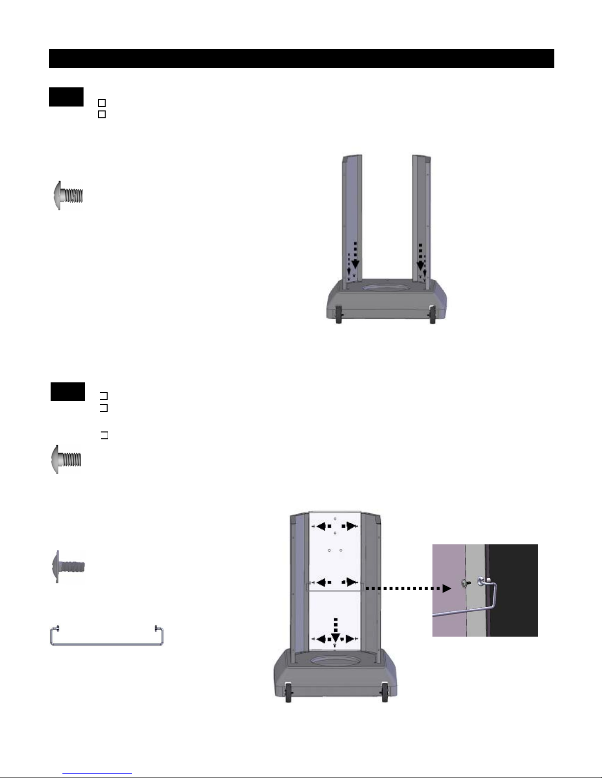
Install Cabinet Left Side Panel and Right Side Panel
1
Attach Cabinet Left Side Panel to the Cabinet Base using 2 Phillips Head Bolts (M6x10mm).
Attach Cabinet Right Side Panel to the Cabinet Base using 2 Phillips Head Bolts (M6x10mm).
Do not fully tighten any bolts at this time.
Phillips Head Bolt M6x10mm
Qty: 4
Assembly Instruction
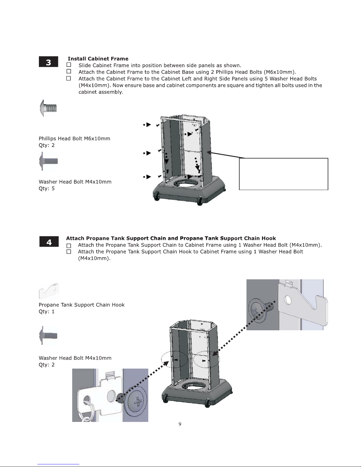
Install Cabinet Front Panel and LP Tank Bracket
2
Attach Cabinet Front Panel to the Cabinet Base using 1 Phillips Head Bolt (M6x10mm).
Attach Cabinet Front Panel to the Cabinet Left and Right Side Panels using 4 Washer Head Bolts
using the top and lower holes(M4x10mm). Do not fully tighten any bolts at this time.
At tach LP Tank Bra cket t o cen ter h ole s of C abi net F ron t Pane l us ing 2 Washe r He ad Bo lts as Sh own
Phillips Head Bolt M6x10mm
Qty: 1
Washer Head Bolt M4x10mm
Qty: 6
LP Tank Bracket
Qty: 1
8
Note: Do not install this
center bolt a t this time.
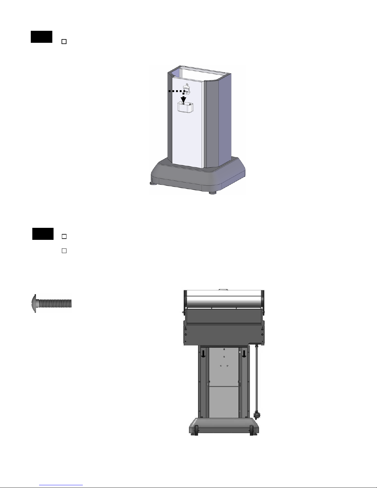
Hang Bottle Cap Catcher
5
Hang Bottle Cap Catcher on the Cabinet Front Panel.
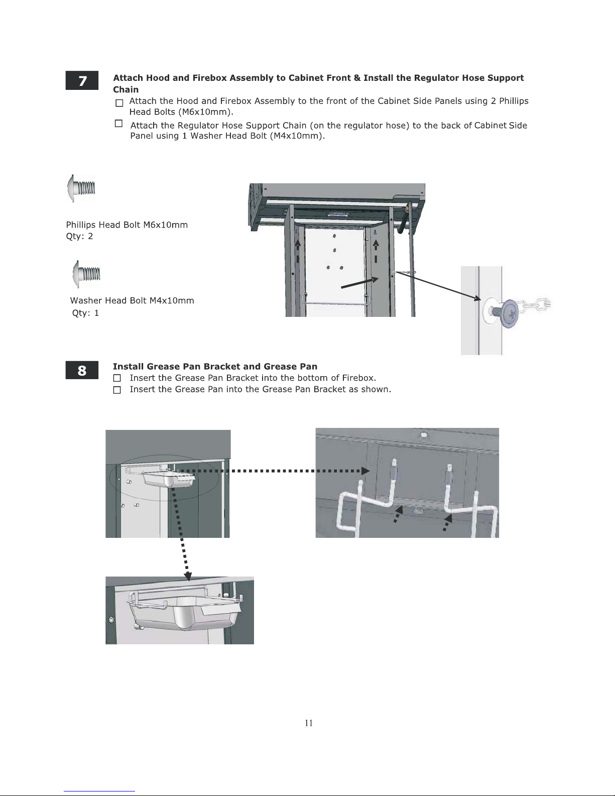
Install Hood and Firebox Assembly
6
Remove regulator and hose from underside of Hood and Firebox Assembly. Remove packing
from regulator.
With the aid of an assistant, place Hood and Firebox Assembly onto the Cabinet, and attach to
the Cabinet Frame using 2 Phillips Head Bolts (M6x25mm).
Phillips Head Bolt M6x25mm
Qty: 2
10
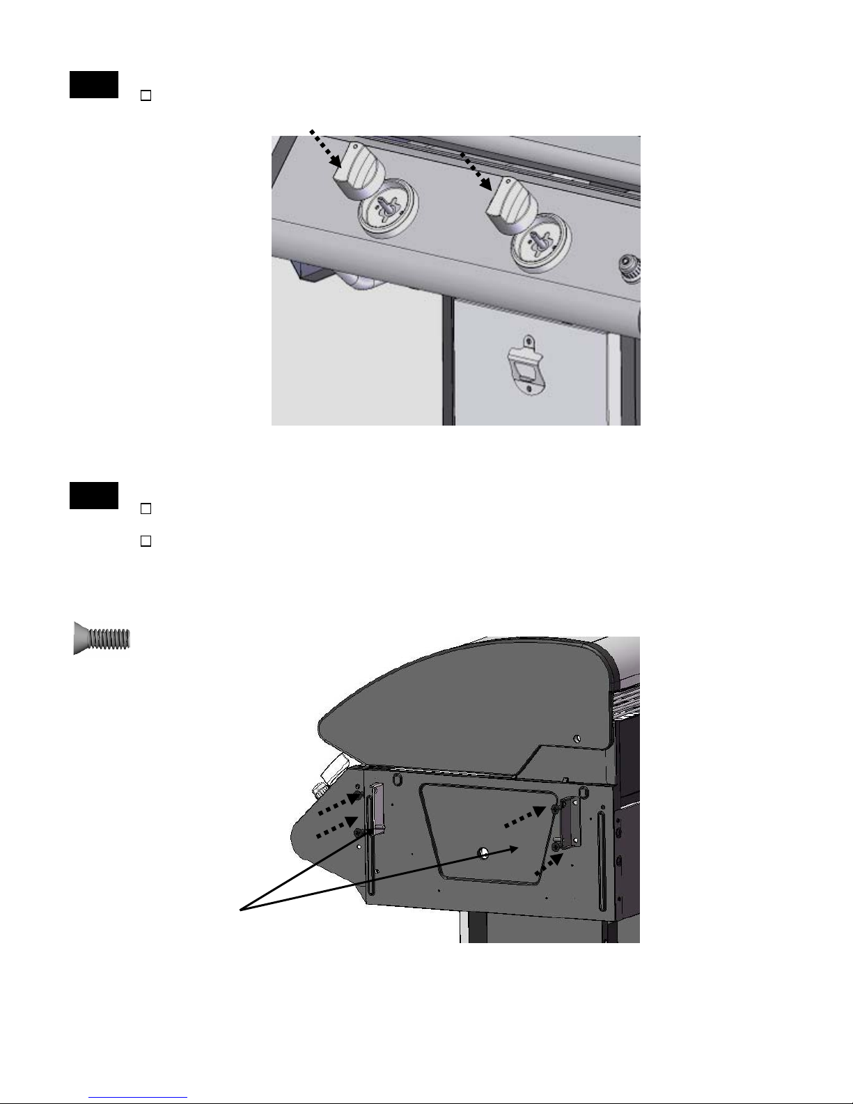
Install Control Knobs
9
10
Attach Side Shelf Right Front Support and Side Shelf Right Back Support to Firebox using 4 Flat
Head Bolts (M6x12mm)
Press 2 Control Knobs onto the valve stems as shown.
Install Side Shelf Supports to Firebox
.
Attach Side Shelf Left Front Support and Side Shelf Left Back Support to Firebox using 4 Flat
Head Bolts (M6x12mm)
Note: Position the supports so that the pins are at the bottom of the supports and extend
towards the center of the Firebox.
.
Flat Head Bolt M6x12mm
Qty: 8
Pin
12
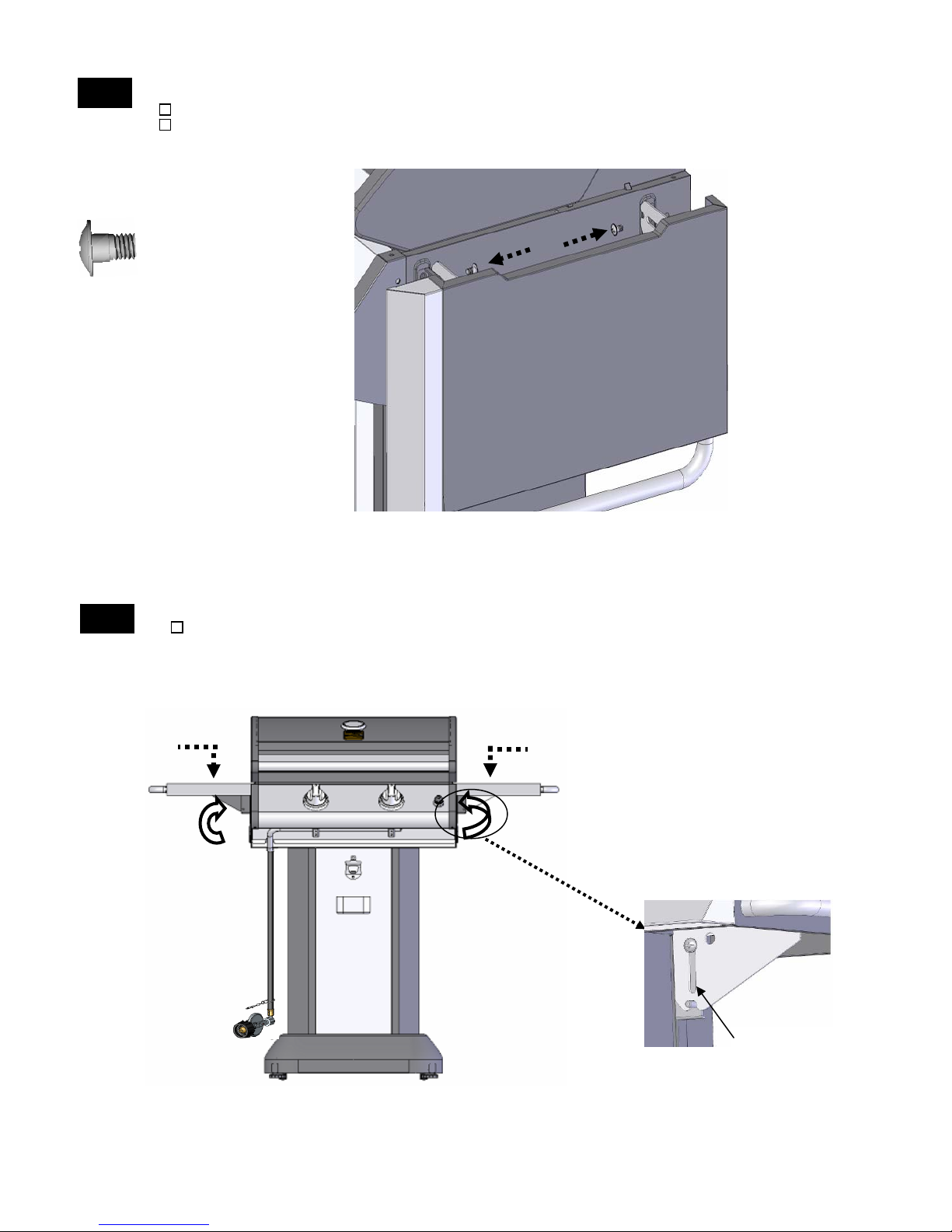
Attach Side Shelves
11
Position Shelf Brackets to the inside of the Shelf Supports.
Attach Left and Right Shelves to Shelf supports with two Step Bolts(M6) each. Securely tighten bolts.
Step Bolt M6
Qty: 4
Side Shelf Operation
12
Pull up on the Left Side Shelf and slide down over the support pins to secure in the upright
position. Repeat the same procedure on the Right Shelf. To lower, slide shelves up and fold down
into storage position.
Pin
13
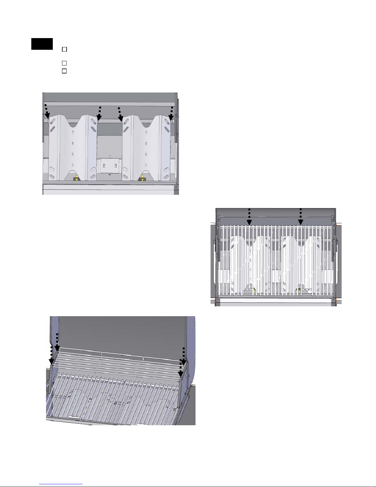
Install the Heat Diffusers, Cooking Grates, Warming Rack
13
Insert the Heat Diffusers into the firebox by placing them into the indentations along the front
and back of the firebox. See Figure 1.
Place the Cooking Grates into the firebox. See Figure 2.
Insert the Warming Rack into the slots of firebox side panels as shown. See Figure 3.
Figure 1
Figure 2
Figure 3
14

Install Grill Transport Handle
14
Attach Transport Handle and 2 Handle Heat Shields to the back of the Firebox using 4 Flat Head
Bolts (M6x25mm).
Grill Transport Handle Heat Shield
Qty: 2
Flat Head Bolt M6x25mm
Qty: 4
Place and Secure LP Cylinder into the Cabinet
15
Be sure the LP cylinder is "OFF" by turning the hand wheel clockwise until it stops. Place the LP
cylinder down into the tank support hole in the bottom of the cabinet. Be sure the grill burner
controls are turned to the "OFF" position. Remove the safety cap from the cylinder valve. Center the
nipple of the grill regulator into the cylinder and turn the black nut clockwise until it stops. Hand
tighten only.
Hang the Propane Tank Support Chain around the LP tank and attach to its hook to secure the
tank.
Propane Tank Support Chain
Qty: 1
15
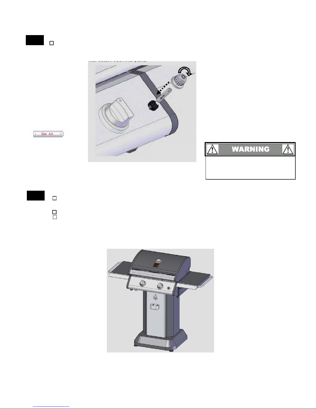
Install Battery
16
Unscrew the electronic igniter button. Place the AA Battery into the igniter with the positive (+) end
up. Screw the electronic igniter button back into place.
Battery (Size AA)
Qty: 1
Do not dispose batteries into
fire as they may leak or
explode.
Congratulations – Assembly is now complete!
17
Remove any additional labels or packing material from the grill except the CSA label. Be sure to
clean all foam packing material out of all areas.
Level your grill by adjusting the 2 front feet.
Please proceed to and read the remaining sections of the Use & Care Guide prior to operating your
grill.
16

Grill Transport
18
Grasp Grill Transport Handle with one hand and Grill Hood Handle with the other. Place foot
against back of grill base for leverage. Tilt grill back onto wheels to transport.
CAUTION: Grill must be completely cooled down before transporting.
17
 Loading...