

Kenmore 117.552, 117.812, 117.813, 117.560 Instructions Manual
%j4.4Z
OWNt
1
0-4
Cet’tijficate
the
guarantee
We
ing
head
family
workmanship
and
date
from
prove
parts
manship,
machine
the
or
Simpsons-Sears
returning
securely.
parts
or
from
cluded
further
We
be
date
When
ing
model
We
to
any
sewing
in.
the
For
machine
free
of
us
do
make
liability
Any
foregoing
ready
Model
Cabinet
from
referring
number.
not
this
of
to
use
purchase.
of
to
they
toamail
(Needles,
which
the
guarantee
defects
purchase.
about
authorize
any
other
in
machine
agreements
reference
this
on
No.
Model
ond
to
machine
be
free
for
defective
be
will
be
is
returned
retail
order
belts,
wear
out
guarantee.)
for
this
to
your
machine,
any
guarantee
connection
other
shallbevoid
page.
No.
SEARS,
SIMPSONS-SEARS
cjf
original
when
from
a
period
the
In
replaced
to
or
store,
bobbins,
from
all
electrical
period
a
guarantee
person
with
those
than
outside
and
record
ROEBUCK
iatan
purchaser
used
defects
of
twenty
event
material
free
the
order
be
natural
of
always
or
to
or
the
contained
or
contradictory
of
number
Read
Date
that
nearest
sure
shuttles,
equipment
one
or
representative
assume
no
in
mail
the
tee
the
for
normal
in
material
working
or
of
charge
store.
and
are
use
year
when
mention
for
sale
of
effect.
of
Serial
Delivered
AND
LIMITED
sew
years
work
Sears
pack
bulbs,
ex
from
writ
the
this
here
your
No.
CO.
We
in
service.
carefully
yourself
over
of
tighten
cord
Unwind
into
drive
Book
directions
are
machine
this
even
other
cabinet
round
cut-out
head
near
as
cord
back
the
any
operation.
for
merely
pulley
connections.
TO
11
extremely
Therefore
and
with
though
make.
Head
and
shanks
in
hinge
into
into
extension
base
IMPOR
AND
top
to
slot
12.
for
thor
the
you
slide
the
hole
plug
place
as
re
of
of
set
at
of
This
Object
The
sewing
this
your
to
order
this
head
lug
head
2)
possible
plate
(see
the
the
around
is
you
in
read
sewing
holes
attached
securely.
up
cabinet,
machine
is
no
provide
In
is
—
operating
anxious
turns
you
oughly
if
In
to
us
to
a
operation
tony
head
the
cabinet.
screws
motor
edge
in
cord
outlet,
leather
course
GIVE
TANT
that
the
urged
are
iii
be
accustomed
To
Install
the
luee
hinge
hinges
two
Tip
(Fig.
bushing
Pull
as
bed
of
plate
bed
inside
and
machine
If
belt
there
PARTICULAR
INFORMATION
e
utmost
of
of
with
machine.
investment
satisfactory
this
familiarize
to
to
machine,
using
Sewing
On
Cabinet
top
on
(Fig.
to
and
back
motor
on
and
slip
push
and
Fig.
9).
is
treadle
hand
or
motor
IMPORTANT
ATTENTION
ON
complete
book
some
Machine
of
open
2)
back
motor
bushing
plug
ready
operated,
wheel
electrical
PAGES
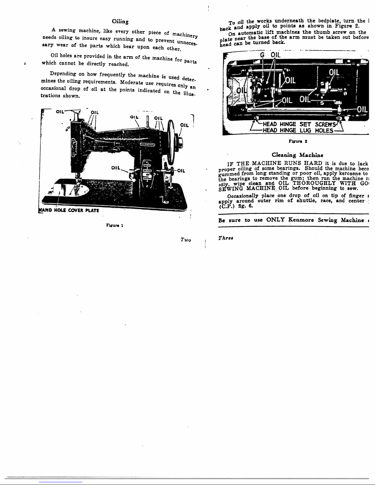
A
needs
sary
wear
Oil
which
Depending
mines
the
occasional
trations
sewing
oiling
holes
cannot
oiling
drop
shown.
machine,
to
insure
of
the
are
provided
be
on
requirements.
of
parts
directly
how
oil
Oiling
like
every
easy
running
which
in
the
reached.
frequently
at
the
other
bear
arm
of
the
Moderate
points
piece
and
to
upon
the
machine
use
indicated
of
prevent
each
machine
is
require
5
on
machinery
unneee
other.
for
used
only
the
Parts
deter.
ilins.
back
plate
bead
‘
On
oil
and
automatiC
near
c&fl
the
apply
the
be
works
base
turned
oil
li-ft
underneath
points
to
machines
the
of
back.
as
arm
the
shown
the
must
bedplate,
thumb
be
in
screw
taken
turn
Figure
out
on
before
I
the
2.
the
a
r
hAND
OILL
HOLE
COVER
OIL
PLATE
Figure
OIL
1
Figure
2
Cleaning
MACHINE
THE
IF
proper
gummed
bearings
the
wipe
idly
SE*ING
Occasionally
apply
(C.P.)
sure
1
Two
Be
Three
oiling
from
clean
MACHINE
around
fig.
to
of
long
to
outer
6.
use
some
standing
remove
and
place
ONLY
bearings.
the
OIL
OIL
one
rim
Machine
RUNS
HARD
Should
or
poor
gum;
then
THOROUGHLY
before
drop
of
shuttle,
of
Kenmore
it
the
oil,
apply
run
beginning
oil
on
race,
Sewing
is
due
machine
kerosene
the
WITH
to
tip
and
to
machine
sew.
of
finger
center
Machine
lack
beco
to
GO
ri
i
(See
Fgiire
enlarged
3
view
of
tension
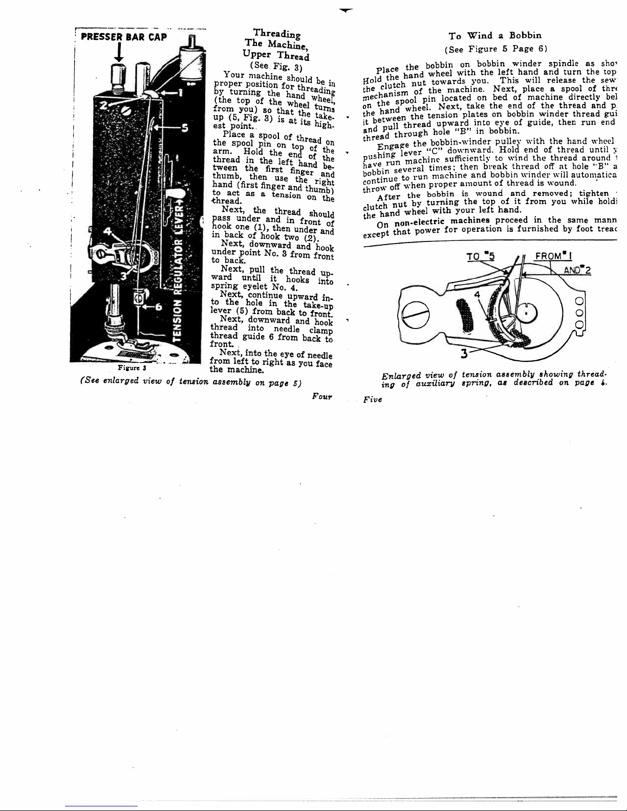
Your
proper
by
turning
(the
from
up
(5,
est
point.
Place
the
spool
arm.
thread
tween
thumb,
hand
to
act
thread,
Next,
pass
oak
in
back
Next,
under
to
back.
Next,
ward
spring
Next,
to
the
lever
Next,
thread
thread
front.
Next,
from
the
machine.
assembly
The
Upper
machine
POS1tjOfl
top
you)
Fig.
Hold
in
the
then
(first
as
under
one
of
downward
point
pull
until
eyelet
Continue
hole
(5)
downward
into
guide
into
left
Threading
Machine,
(See
Fig.
the
Of
the
so
that
3)
a
spool
pin
on
the
the
first
use
finger
a
tension
the
thread
and
(1),
then
hook
No.
the
it
No.
in
from
back
needle
6
the
to
right
on
page
Thread
3)
ShoUld
for
hand
wheel
is
at
of
top
ena
left
finger
the
and
in
under
two
3
from
thread
hooks
4.
upward
the
and
from
eye
as
5)
be
threading
wh
tu
the
take
its
thre
of
the
of
the
hand
be..
and
right
thumb)
on
the
should
front
and
(2).
and
hook
front
up
into
i
takeup
to
front.
hook
clamp
back
of
needle
you
face
Four
Bobbin
Figure
bobbin
the
YOU.
on
into
in
break
and
wound
top
left
a
5
left
This
Next,
bed
the
bobbin
on
eye
bobbin.
pulley
Hold
to
bobbin
thread
of
of
hand.
proceed
Page
winder
hand
of
end
of
wind
thread
and
it
will
place
machine
of
guide,
with
end
the
winder
is
removed;
from
in
6)
spindle
and
release
a
the
winder
the
of
thread
off
viIl
wound.
you
the
turn
spool
directly
thread
thread
then
hand
thread
hole
at
automatica
while
same
by
as
the
the
of
run
until
around
tighten
foot
sha
top
sew
thr
and
gui
end
wheel
“B’
-
holdi
mann
trea
be]
,
I
a
Wind
To
(See
place
the
1{0
i
of
1d
clutch
the
inecmsm
the
fl
hand
the
between
it
null
and
thread
Engage
shin
rn
have
bobbin
contin
throw
After
clutch
hand
the
On
except
spool
through
several
off
nut
non.electriC
that
hand
nut
of
wheel.
the
thread
the
lever
machine
run
to
when
the
by
wheel
power
wheel
the
pin
tension
“C”
times;
proper
bobbin
turning
bobbin
the
on
with
towards
machine.
located
take
Next,
plates
upward
“B
hole
bobbin-winder
downward.
sufficiently
then
machine
amount
is
the
your
with
machines
operationisfurnished
for
to
on
thread.
page
4.
Five
Enlarged
of
ing
view
auxiliary
of
tension
spring,
assembly
as
described
showing
BOBBIN
CASE
OGLE
BOBBIN
If
STOP
SCREW
u
CoNL
WINDER
PULLEy
Sz
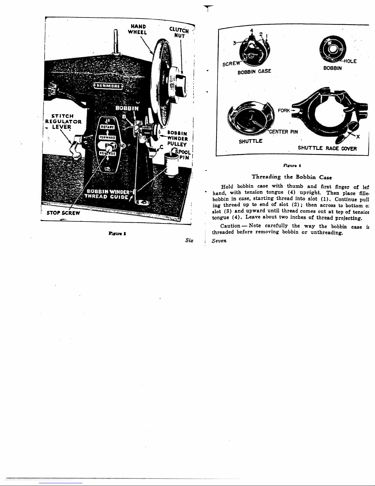
Hold
hand,
bobbin
thread
ing
(3)
slot
tongue
Caution
threaded
Seven
SHUTTLE
bobbin
with
cnse,
in
and
(4).
before
tension
U
upward
Leave
—
Note
Threading
case
tongue
starting
end
to
until
about
carefully
removing
with
thread
of
xu
the
slot
thread
two
bobbin
Bobbin
thumb
(4)
into
(2);
inches
the
7x
and
upright.
slot
then
conies
of
way
or
unthreading.
Case
first
(1).
across
out
thread
the
finger
Then
Continue
at
top
projecting.
bobbin
to
place
bottom
of
of
flI1e
pull
tensioz
case
let
o:
N

While
thread
inches),
with
cornea
and
thread
the
hole.
foot,
extending
turn
right
the
Lead
keeping
To
To
holding
the
hand,
back
you
the
the
Remove
gu
Draw
up.
are
ends
loosely
through
of
top
until
The
holding
of
upper
the
Up
in
hand
the
lower
both
thread
Bobbin
Lower
the
eye
needle
and
threads
left
of
wheel
thread
come
in
Case
Turn
wise)
3)
Then
cover
reach
Clasp
the
your
Fig.
finger
and
readily
Follow
in
in
spindle
fits
shuttle,
Thread
hand,
needle
from
goes
will
up
back
presser
from
hand
until
at
is
remove
plate
down
thumb
left
7.
Then
lift
the
replacing
shuttle.
The
over
the
(three
:,OU
all
the
fonn
through
under
foot
take-up
its
permitting
to
the
bobbin
and
hand
with
up
bobbin
removed.
the
same
the
hole
inside
the
center
as
shown
end
way
a
loop
the
the
slot.
Shuttle
wheel
highest
the
hand
bobbin.
first
as
the
on
case
bobbIn
in
the
the
bottom
of
or
OClcwiae)
do
°‘er
nee.fle
(clock.
(5,
Fig.
point
hole
YOU
case
with
finger
shown
second
latch
“s”
can
procedure
center
of
pin
in
Fig.
Eigkt
to
of
j
be
case
case
the
6.
First
on
bACk
iained.
point
press
shuttle
the
from
shuttle
OUT
Turn
entering
finger
(CP,
opposite
exactly
lined
over
5
huttle
FORCED
place
under
which
Nine
Remove
remove
its
Next,
the
of
end
rear
under
iCP,
FORCE.
the
the
the
of
Fig.
each
in
the
U,
tail
the
be
shuttle
pin
will
hinges.
turn
nele
of
cover
race
Pin
Fig.
hand
needle
left
so
8)
other
with
line
SHARP
of
properly
position.
into
race
(H)
snap
Shuttle
the
Next,
is
latch
H.
8)
To
wheel
band,
the
the
and
back
hand
the
just
G,
(Fig.
Next,
and
Replace
plate
centers
in
the
point
arrow
placed
cover
push
to
from
Pigur.
hole
remove
hand
entering
shown
6)take
it
until
hole.
hold
the
driving
of
in
When
by
right
its
8
wheel
in
so
be
can
the
the
the
of
outer
pins
shuttle
(S).
the
the
slipping
holding
the
cover
bobbin
needle
Fig.
may
it
hold
readily
Shuttle
point
With
shuttle
the
edge
It
race,
shuttle
side
position.
Shuttle
plate
case
(clockwise)
plate
This
8.
be
readily
the
of
removed
the
of
thumb
the
by
slotted
the
of
(DP).
be
will
imperative
is
it
and
is
fork
the
back
and
as
center
needle
the
holes,
When
almost
must
in
over
Race
tip
already
until
hole.
will
removed
and
center
shuttle,
properly
that
never
position
left
at
latch
head
ex
the
Then
release
pin
WITH
just
is
first
pin
directly
are
directly
the
side
(G)
in
be
re
 Loading...