

Kenmore 110.C8787*, 110.C8789* Owner's Manual
®
Electric Dryer
Use & Care Guide
Sécheuse électrique
Guide d’utilisation et d’entretien
Models/Modèles 110.C8787✼, C8789✼
✼ = color number/numéro de couleur
W10182355A Sears Canada Inc., Toronto, Ontario, Canada M5B 2B8 www.sears.ca

TABLE OF CONTENTS
PROTECTION AGREEMENTS
PROTECTION AGREEMENTS.......................................................2
WARRANTY.....................................................................................3
DRYER SAFETY..............................................................................4
INSTALLATION INSTRUCTIONS ..................................................5
Tools and Parts ............................................................................5
Optional Pedestal.........................................................................5
Location Requirements ...............................................................5
Electrical Requirements................................................................7
Venting Requirements..................................................................8
Plan Vent System .........................................................................9
Install Vent System.................................................................... 10
Install Leveling Legs .................................................................. 10
Connect Vent............................................................................. 11
Level Dryer................................................................................. 11
Reverse Door Swing.................................................................. 11
Complete Installation................................................................. 12
DRYER USE ................................................................................. 13
Starting Your Dryer.................................................................... 13
Stopping Your Dryer.................................................................. 14
Pausing or Restarting................................................................ 14
Control Locked.......................................................................... 14
Drying and Cycle Tips ............................................................... 14
Status Lights.............................................................................. 15
Cycles........................................................................................ 15
Options ...................................................................................... 16
Modifiers.................................................................................... 17
Changing Cycles, Options and Modifiers ................................. 17
End of Cycle Signal ................................................................... 17
TUMBLE FREE™ Heated Dryer Rack....................................... 17
DRYER CARE.............................................................................. 18
Cleaning the Dryer Location...................................................... 18
Cleaning the Lint Screen........................................................... 18
Cleaning the Dryer Interior ........................................................ 19
Removing Accumulated Lint..................................................... 19
Vacation and Moving Care........................................................ 19
Changing the Drum Light .......................................................... 19
TROUBLESHOOTING.................................................................. 20
SERVICE NUMBERS ............................................... BACK COVER
Master Protection Agreements
Congratulations on making a smart purchase. Your new
Kenmore® product is designed and manufactured for years of
dependable operation. But like all products, it may require
preventive maintenance or repair from time to time. That’s when
having a Master Protection Agreement can save you money and
aggravation.
The Master Protection Agreement also helps extend the life of
your new product. Here’s what the Agreement* includes:
✔ Parts and labor needed to help keep products operating
properly under normal use, not just defects. Our coverage
goes well beyond the product warranty. No deductibles, no
functional failure excluded from coverage— real protection.
✔ Expert service by a force of more than 10,000 authorized
Sears service technicians, which means someone you can
trust will be working on your product.
✔ Unlimited service calls and nationwide service, as often as
you want us, whenever you want us.
✔ “No-lemon” guarantee – replacement of your covered
product if four or more product failures occur within twelve
months.
✔ Product replacement if your covered product can’t be fixed.
✔ Annual Preventive Maintenance Check at your request – no
extra charge.
✔ Fast help by phone – we call it Rapid Resolution – phone
support from a Sears representative on all products. Think of
us as a “talking owner’s manual.”
✔ Power surge protection against electrical damage due to
power fluctuations.
✔ $250 Food Loss Protection annually for any food spoilage
that is the result of mechanical failure of any covered
refrigerator or freezer.
✔ Rental reimbursement if repair of your covered product takes
longer than promised.
✔ 10% discount off the regular price of any non-covered repair
service and related installed parts.
Once you purchase the Agreement, a simple phone call is all that
it takes for you to schedule service. You can call anytime day or
night, or schedule a service appointment online.
The Master Protection Agreement is a risk free purchase. If you
cancel for any reason during the product warranty period, we will
provide a full refund. Or, a prorated refund anytime after the
product warranty period expires. Purchase your Master
Protection Agreement today!
Some limitations and exclusions apply. For prices and
additional information in the U.S.A. call 1-800-827-6655.
*Coverage in Canada varies on some items. For full details
call Sears Canada at 1-800-361-6665.
Sears Installation Service
For Sears professional installation of home appliances, garage
door openers, water heaters, and other major home items, in the
U.S.A. or Canada call 1-800-4-MY-HOME
®
.
2

KENMORE ELITE® APPLIANCE WARRANTY
ONE YEAR LIMITED WARRANTY
When installed, operated and maintained according to all
instructions supplied with the product, if this appliance fails due
to a defect in material or workmanship within one year from the
date of purchase, call 1-800-4-MY-HOME
repair.
TWO YEAR LIMITED WARRANTY ON SENSOR SMART™
ELECTRONIC BOARD
For two years from the date of purchase, when this dryer is
installed, operated and maintained according to all instructions
supplied with the product, Sears will replace the electronic
control board if defective in materials or workmanship. After the
first year, customer assumes any labor costs associated with
replacement of these parts.
If this appliance is used for other than private family purposes,
this warranty applies for only 90 days from the date of purchase.
THIS WARRANTY COVERS ONLY DEFECTS IN MATERIAL
AND WORKMANSHIP. SEARS WILL NOT PAY FOR:
1. Expendable items that can wear out from normal use,
including but not limited to filters, belts, light bulbs, and bags.
2. A service technician to instruct the user in correct product
installation, operation or maintenance.
3. A service technician to clean or maintain this product.
4. Damage to or failure of this product if it is not installed,
operated or maintained according to all instructions supplied
with the product.
5. Damage to or failure of this product resulting from accident,
abuse, misuse or use for other than its intended purpose.
6. Damage to or failure of this product caused by the use of
detergents, cleaners, chemicals or utensils other than those
recommended in all instructions supplied with the product.
7. Damage to or failure of parts or systems resulting from
unauthorized modifications made to this product.
®
to arrange for free
DISCLAIMER OF IMPLIED WARRANTIES; LIMITATION OF
REMEDIES
Customer’s sole and exclusive remedy under this limited
warranty shall be product repair as provided herein. Implied
warranties, including warranties of merchantability or fitness for a
particular purpose, are limited to one year or the shortest period
allowed by law. Sears shall not be liable for incidental or
consequential damages. Some states and provinces do not allow
the exclusion or limitation of incidental or consequential
damages, or limitations on the duration of implied warranties of
merchantability or fitness, so these exclusions or limitations may
not apply to you.
This warranty applies only while this appliance is used in the
United States and Canada.
This warranty gives you specific legal rights, and you may also
have other rights which vary from state to state.
Sears, Roebuck and Co.
Dept. 817WA, Hoffman Estates, IL 60179
Sears Canada Inc.
Toronto, Ontario, Canada M5B 2B8
PRODUCT RECORD
In the space below, record your complete model number, serial
number, and purchase date. You can find this information on the
model and serial number label located on the product.
Have this information available to help you obtain assistance or
service more quickly whenever you contact Sears concerning
your appliance.
Model number __ __ __. __________________________________________
Serial number___________________________________________________
Purchase date __________________________________________________
Save these instructions and your sales receipt for future
reference.
3
DRYER SAFETY
Your safety and the safety of others are very important.
We have provided many important safety messages in this manual and on your appliance. Always read and obey all safety
messages.
This is the safety alert symbol.
This symbol alerts you to potential hazards that can kill or hurt you and others.
All safety messages will follow the safety alert symbol and either the word “DANGER” or “WARNING.”
These words mean:
You can be killed or seriously injured if you don't immediately
DANGER
WARNING
All safety messages will tell you what the potential hazard is, tell you how to reduce the chance of injury, and tell you what can
happen if the instructions are not followed.
IMPORTANT SAFETY INSTRUCTIONS
WARNING:
including the following:
■
Read all instructions before using the dryer.
■
Do not place items exposed to cooking oils in your dryer.
Items contaminated with cooking oils may contribute to
a chemical reaction that could cause a load to catch fire.
■
Do not dry articles that have been previously cleaned in,
washed in, soaked in, or spotted with gasoline, drycleaning solvents, or other flammable or explosive
substances as they give off vapors that could ignite or
explode.
■
Do not allow children to play on or in the dryer. Close
supervision of children is necessary when the dryer is
used near children.
■
Before the dryer is removed from service or discarded,
remove the door to the drying compartment.
■
Do not reach into the dryer if the drum is moving.
■
Do not install or store the dryer where it will be exposed
to the weather.
■
Do not tamper with controls.
To reduce the risk of fire, electric shock, or injury to persons when using the dryer, follow basic precautions,
follow instructions.
can be killed or seriously injured if you don't
You
instructions.
■
Do not repair or replace any part of the dryer or attempt
any servicing unless specifically recommended in this
Use and Care Guide or in published user-repair
instructions that you understand and have the skills to
carry out.
■
Do not use fabric softeners or products to eliminate static
unless recommended by the manufacturer of the fabric
softener or product.
■
Do not use heat to dry articles containing foam rubber or
similarly textured rubber-like materials.
■
Clean lint screen before or after each load.
■
Keep area around the exhaust opening and adjacent
surrounding areas free from the accumulation of lint, dust,
and dirt.
■
The interior of the dryer and exhaust vent should be
cleaned periodically by qualified service personnel.
■
See installation instructions for grounding requirements.
follow
SAVE THESE INSTRUCTIONS
4
INSTALLATION INSTRUCTIONS
Tools and Parts
Gather the required tools and parts before starting installation.
Read and follow the instructions provided with any tools listed
here.
■ Flat-blade screwdriver
■ #2 Phillips screwdriver
■ Adjustable wrench that
opens to 1" (2.54 cm) or
hex-head socket wrench
(for adjusting dryer feet)
■ Level
■ Vent clamps
Parts supplied
Remove parts package from dryer drum. Check that all parts are
included.
4 Leveling legs
NOTE: Do not use leveling legs if installing the dryer on a
pedestal.
■ Caulking gun and
compound (for installing
new exhaust vent)
■ Tin snips (new vent
installations)
■ ¼" nut driver or socket
wrench
■ Tape measure
For a garage installation, you will need to place the 10" (25.4 cm)
pedestal at least 9" (22.9 cm) above the floor. You will need to
place the 15.5" (39.4 cm) pedestal at least 3" (7.6 cm) above the
floor.
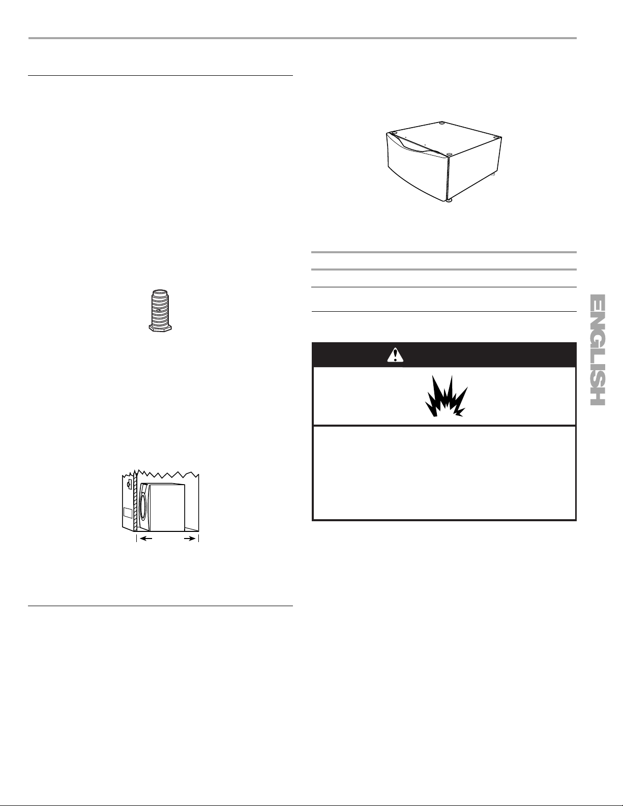
Optional pedestal (15.5" [39.4 cm] model shown)
To order, call your local Sears store. For further information,
please call 1-800-4-MY-HOME
®
(1-800-469-4663).
Pedestal Height Color Part Number
10" (25.4 cm) White 46822
15.5" (39.4 cm) White 57822
Location Requirements
WARNING
Parts needed
Check local codes. Check existing electrical supply and venting.
See “Electrical Requirements” and “Venting Requirements”
before purchasing parts.
■ For close-clearance installations between 31.5" (80.01 cm)
and 37" (93.98 cm), see “Plan Vent System” section for
venting requirements.
37"
(93.98 cm)
Mobile home installations require metal exhaust system hardware
available for purchase from your local Sears store or Sears
Service Center. For further information, please call
1-800-4-MY-HOME
®
(1-800-469-4663).
Optional Pedestal
Are you placing the dryer on a pedestal? You have the option of
purchasing pedestals of different heights separately for this dryer.
You may select a 10" (25.4 cm) pedestal or a 15.5" (39.4 cm)
pedestal with a storage drawer. The pedestal will add to the total
height of the dryer for a total height of approximately
46" (116.8 cm) or 51.5" (130.8 cm), respectively.
Explosion Hazard
Keep flammable materials and vapors, such as
gasoline, away from dryer.
Place dryer at least 18 inches (46 cm) above the floor
for a garage installation.
Failure to do so can result in death, explosion, or fire.
You will need
■ A location that allows for proper exhaust installation. See
“Venting Requirements.”
■ A separate 30-amp circuit.
■ A grounded electrical outlet located within 2 ft (61 cm) of
either side of the dryer. See “Electrical Requirements.”
■ A sturdy floor to support the total dryer weight of 200 lbs
(90.7 kg). The combined weight of a companion appliance
should also be considered.
■ A level floor with a maximum slope of 1" (2.5 cm) under entire
dryer. (If slope is greater than 1" [2.5 cm], install Extended
Dryer Feet Kit, Part Number 279810.) Clothes may not tumble
properly and automatic sensor cycles may not operate
correctly if dryer is not level.
■ For a garage installation, you will need to place the dryer at
least 18" (46 cm) above the floor. If you are using a pedestal,
you will need 18" (46 cm) to the bottom of the dryer.
5
Do not operate your dryer at temperatures below 45ºF (7ºC). At
lower temperatures, the dryer might not shut off at the end of an
automatic cycle. Drying times can be extended.
The dryer must not be installed or stored in an area where it will
be exposed to water and/or weather.
Check code requirements. Some codes limit, or do not permit,
installation of the dryer in garages, closets, mobile homes or
sleeping quarters. Contact your local building inspector.
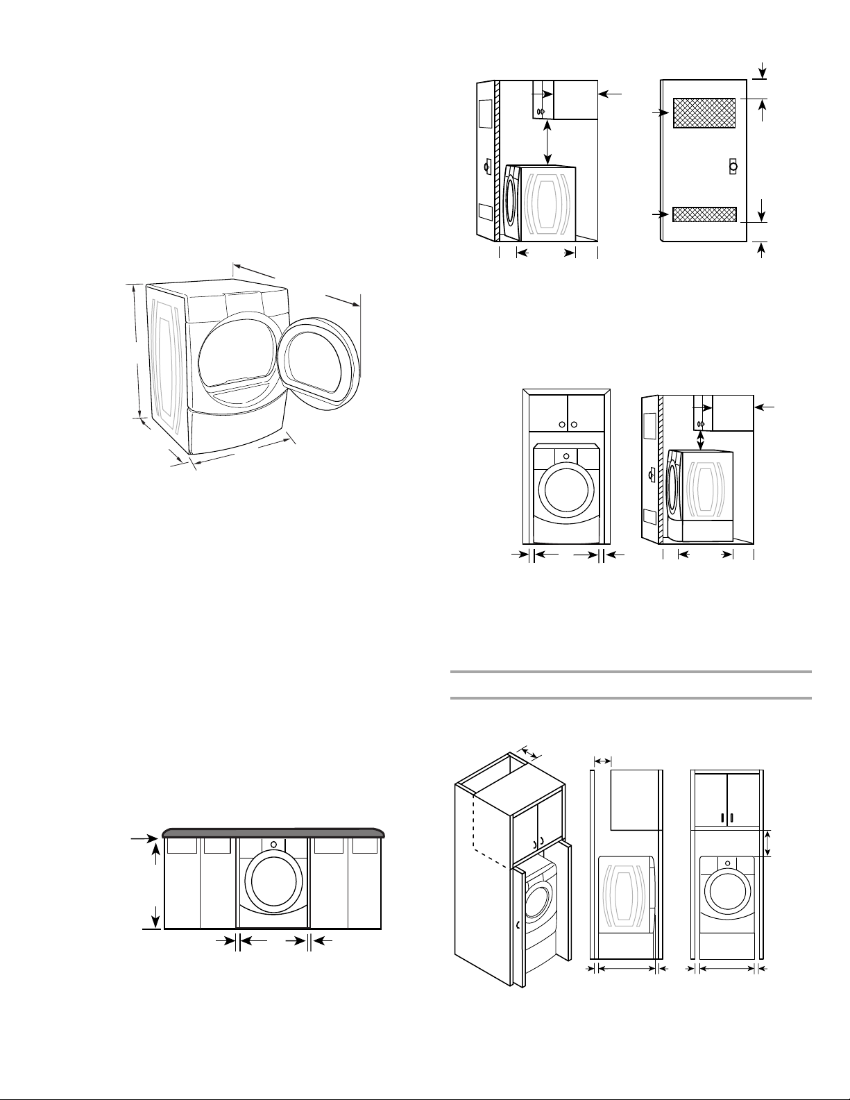
Installation clearances
The location must be large enough to allow the dryer door to
open fully.
Dryer Dimensions
50½"
(128.27 cm)
Closet installation - Dryer only
14" max.*
(35.6 cm)
18" min.*
(45.72 cm)
(155 cm2)
1"*
(2.5 cm)
31½"
(80 cm)
5"**
(12.7 cm)
A
A. Side view - closet or confined area
B. Closet door with vents
48 in.
(310 cm2)
24 in.
3"*
(7.6 cm)
2*
2*
3"*
(7.6 cm)
B
38"
(96.52 cm)
*31½"
(80.01 cm)
27"
(68.6 cm)
*Most installations require a minimum 5" (12.7 cm) clearance
behind the dryer for the exhaust vent with elbow. See “Venting
Requirements.”
Installation spacing for recessed area or closet installation
The following spacing dimensions are recommended for this
dryer. This dryer has been tested for spacing of 0" (0 cm)
clearance on the sides and rear. Recommended spacing should
be considered for the following reasons:
■ Additional spacing should be considered for ease of
installation and servicing.
■ Additional clearances might be required for wall, door and
floor moldings.
■ Additional spacing should be considered on all sides of the
dryer to reduce noise transfer.
■ For closet installation, with a door, minimum ventilation
openings in the top and bottom of the door are required.
Louvered doors with equivalent ventilation openings are
acceptable.
■ Companion appliance spacing should also be considered.
Custom undercounter installation - Dryer only
*Required spacing
**For side or bottom venting, 0" (0 cm) spacing is allowed.
Recessed or closet installation - Dryer on pedestal
14" max.*
(35.6 cm)
18" min.*
(45.72 cm)
1"
(2.5 cm)
27"
(68.6 cm)
1"
(2.5 cm)
A
A. Recessed area
B. Side view - closet or confined area
1"*
(2.5 cm)
31¹⁄₂"
(80 cm)
B
**
5"
(12.7 cm)
*Required spacing
**For side or bottom venting, 0" (0 cm) spacing is allowed.
Installation spacing for cabinet installation
■ For cabinet installation, with a door, minimum ventilation
openings in the top of the cabinet are required.
7"* (17.8 cm)
7"* (17.8 cm)
0"
(0 cm)
38" min.
(96.52 cm)
*Required spacing
6
1"*
(2.5 cm)
27"
(68.6 cm)
1"*
(2.5 cm)
31¹⁄₂"
(80.0 cm)
1"*
(2.5 cm)
1"
(2.5 cm)
27"
(68.6 cm)
1"
(2.5 cm)
5"**
(12.7 cm)
*Required spacing
**For side or bottom venting, 0" (0 cm) spacing is allowed.
9"*
(22.9 cm)
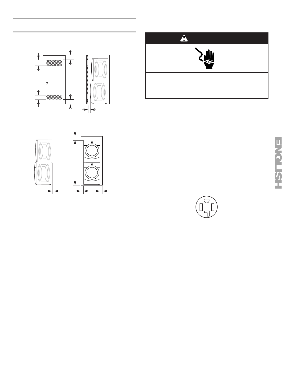
Recommended installation spacing for recessed or
closet installation, with stacked washer and dryer
Electrical Requirements
The dimensions shown are for the recommended spacing.
48 in.2 *
(310 cm2)
3"* (7.6 cm)
3"* (7.6 cm)
2
*
24 in.
(155 cm2)
1"* (2.5 cm)
*Required spacing
6"* (15.2 cm)
76"
(193 cm)
5¹⁄₂"**
(14 cm)
1"
(2.5 cm)
27"
(68.6 cm)
1"
(2.5 cm)
WARNING
Electrical Shock Hazard
Plug into a grounded 4 prong outlet.
Failure to do so can result in death or electrical shock.
It is your responsibility
■ To contact a qualified electrical installer.
■ To be sure that the electrical connection is adequate and in
conformance with the Canadian Electrical Code, C22.1-latest
edition and all local codes. A copy of the above codes
standard may be obtained from: Canadian Standards
Association, 178 Rexdale Blvd., Toronto, ON M9W 1R3
Canada.
■ To supply the required 4 wire, single phase, 120/240 volt,
60 Hz., AC only electrical supply on a separate 30-amp
circuit, fused on both sides of the line. A time-delay fuse or
circuit breaker is recommended. Connect to an individual
branch circuit.
■ This dryer is equipped with a CSA International Certified
Power Cord intended to be plugged into a standard 14-30R
wall receptacle. The cord is 5 ft (1.52 m) in length. Be sure
wall receptacle is within reach of dryer’s final location.
*Required spacing
**For venting out the side, 1" (2.5 cm) spacing is allowed.
Mobile home - additional installation requirements
This dryer is suitable for mobile home installations.
The installation must conform to the Canadian Manufactured
Home Standard, CAN/CSA Z240 MH.
Mobile home installations require:
■ Metal exhaust system hardware, which is available for
purchase from your local Sears store or Sears Service Center.
■ Special provisions must be made in mobile homes to
introduce outside air into the dryer. The opening (such as a
nearby window) should be at least twice as large as the dryer
exhaust opening.
4-wire receptacle 14-30R
■ Do not use an extension cord.
If you are using a replacement power supply cord, it is
recommended that you use Power Supply Cord Replacement
Part Number 3394208.
1-800-4-MY-HOME®
For further information, please call
(1-800-469-4663).
7
GROUNDING INSTRUCTIONS
■
For a grounded, cord-connected dryer:
This dryer must be grounded. In the event of malfunction or
breakdown, grounding will reduce the risk of electric shock
by providing a path of least resistance for electric current.
This dryer is equipped with a cord having an equipmentgrounding conductor and a grounding plug. The plug must
be plugged into an appropriate outlet that is properly
installed and grounded in accordance with all local codes
and ordinances.
WARNING: Improper connection of the equipment-
grounding conductor can result in a risk of electric shock.
Check with a qualified electrician or service representative
or personnel if you are in doubt as to whether the dryer is
properly grounded. Do not modify the plug provided with the
dryer: if it will not fit the outlet, have a proper outlet installed
by a qualified electrician.
SAVE THESE INSTRUCTIONS
Venting Requirements
WARNING
Fire Hazard
Use a heavy metal vent.
Do not use a plastic vent.
Do not use a metal foil vent.
Failure to follow these instructions can result in death
or fire.
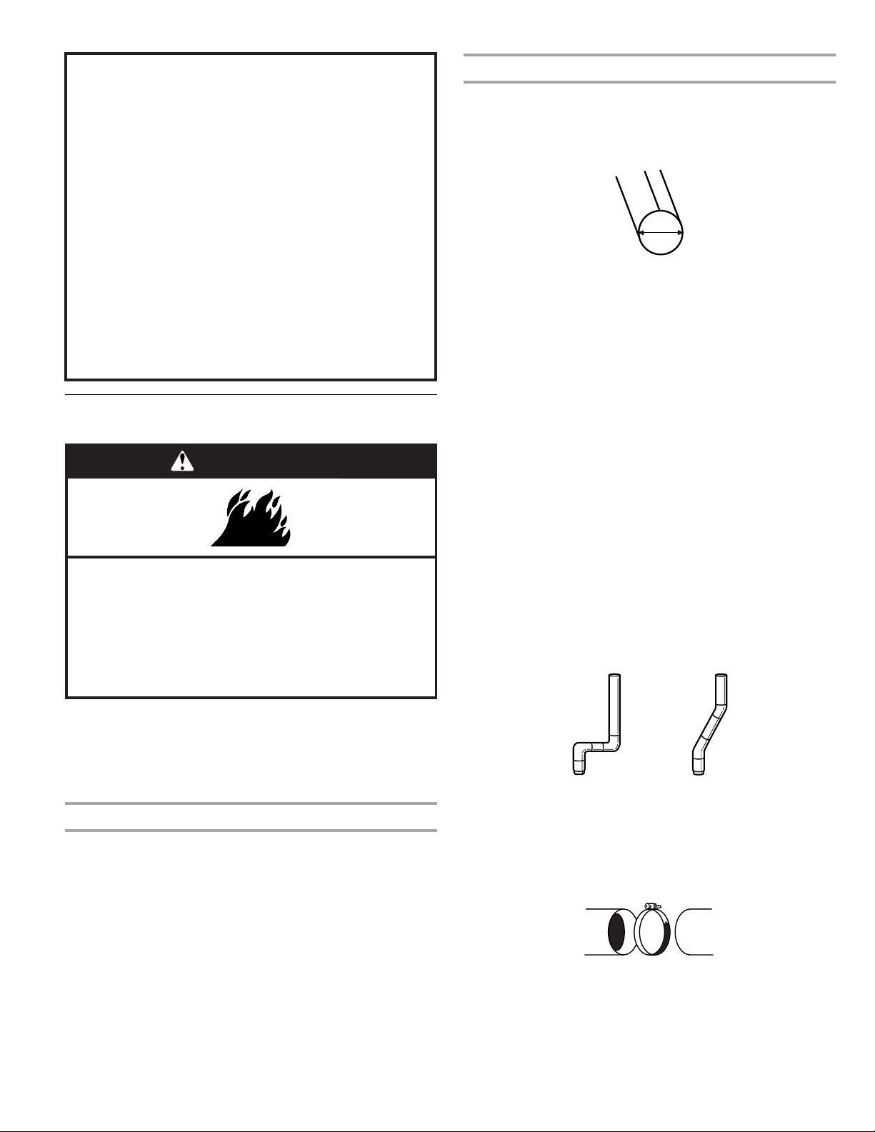
If this is a new vent system
Vent material
■ Use a heavy metal vent. Do not use plastic or metal foil vent.
■ 4" (10.2 cm) heavy metal exhaust vent and clamps must be
used. DURASAFE™ venting products are recommended.
4"
10.2 cm
4" (10.2 cm) heavy metal exhaust vent
DURASAFE™ vent products can be purchased from your
dealer. For further information, please call
1-800-4-MY-HOME
www.sears.com or www.sears.ca.
Rigid metal vent
■ For best drying performance, rigid metal vents are
recommended.
■ Rigid metal vent is recommended to avoid crushing and
kinking.
Flexible metal vent
■ Flexible metal vents are acceptable only if accessible for
cleaning.
■ Flexible metal vent must be fully extended and supported
when the dryer is in its final location.
■ Remove excess flexible metal vent to avoid sagging and
kinking that may result in reduced airflow and poor
performance.
■ Do not install flexible metal vent in enclosed walls, ceilings or
floors.
Elbows
45° elbows provide better airflow than 90° elbows.
®
(1-800-469-4663) or visit our website at
WARNING: To reduce the risk of fire, this dryer MUST BE
EXHAUSTED OUTDOORS.
IMPORTANT: Observe all governing codes and ordinances.
The dryer exhaust must not be connected into any gas vent,
chimney, wall, ceiling or a concealed space of a building.
If using an existing vent system
■ Clean lint from the entire length of the system and make sure
exhaust hood is not plugged with lint.
■ Replace any plastic or metal foil vent with rigid or flexible
heavy metal vent.
■ Review Vent system chart. Modify existing vent system if
necessary to achieve the best drying performance.
8
Good Better
Clamps
■ Use clamps to seal all joints.
■ Exhaust vent must not be connected or secured with screws
or other fastening devices that extend into the interior of the
duct. Do not use duct tape.
Clamp
Exhaust
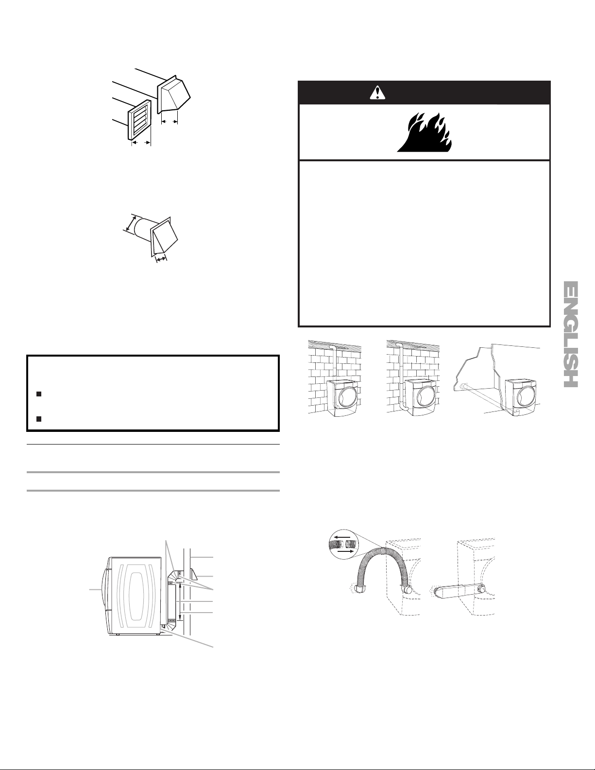
Recommended hood styles are shown here.
B
Optional exhaust installations
This dryer can be converted to exhaust out the right side, left
side, or through the bottom.
dryer converted.
Contact your local dealer to have the
A
4"
(10.2 cm)
4"
(10.2 cm)
A. Louvered hood style
B. Box hood style
The angled hood style (shown here) is acceptable.
4"
(10.2 cm)
2½"
(6.4 cm)
■ An exhaust hood should cap the vent to keep rodents and
insects from entering the home.
■ Exhaust hood must be at least 12" (30.5 cm) from the ground
or any object that may be in the path of the exhaust (such as
flowers, rocks or bushes, snow line, etc.).
■ Do not use an exhaust hood with a magnetic latch.
Improper venting can cause moisture and lint to collect
indoors, which may result in:
Moisture damage to woodwork, furniture, paint, wallpaper,
carpets, etc.
Housecleaning problems and health problems.
Plan Vent System
Choose your exhaust installation type
Recommended exhaust installations
Typical installations vent the dryer from the rear of the dryer.
Other installations are possible.
B
WARNING
Fire Hazard
Cover unused exhaust holes with one of the
following kits:
279818 (white)
279915 (black diamond)
280102 (pacific blue)
280103 (champagne)
280189 (barolo)
Contact your local dealer.
Failure to follow these instructions can result in death,
fire, electrical shock, or serious injury.
A
A. Standard rear offset exhaust installation
B. Left or right side exhaust installation
C. Bottom exhaust installation (not an option
with pedestal installations)
Alternate installations for close clearances
Venting systems come in many varieties. Select the type best for
your installation. Two close-clearance installations are shown.
Refer to the manufacturer’s instructions.
B
C
A
A. Dryer
B. Elbow
C. Wall
D. Exhaust hood
C
D
E
F
G
H
E. Clamps
F. Rigid metal or flexible metal vent
G. Vent length necessary to connect elbows
H. Exhaust outlet
AB
A. Over-the-top installation (also available with one offset elbow)
B. Periscope installation
NOTE: The following kits for close clearance alternate
installations are available for purchase. For further information,
please call 1-800-4-MY-HOME
®
(1-800-469-4663).
9
■ Over-the-Top Installation:
Part Number 26-49900
■ Periscope Installation (For use with dryer vent to wall vent
mismatch):
Part Number 4396037 - 0" (0 cm) to 18" (45.72 cm) mismatch
Part Number 4396011 - 18" (45.72 cm) to 29" (73.66 cm)
mismatch
Part Number 4396014 - 29" (73.66 cm) to 50" (127 cm)
mismatch
Special provisions for mobile home installations
The exhaust vent must be securely fastened to a noncombustible
portion of the mobile home structure and must not terminate
beneath the mobile home. Terminate the exhaust vent outside.
Number of
90º turns
or elbows
0Rigid metal
1Rigid metal
2Rigid metal
3Rigid metal
4Rigid metal
Type of
vent
Flexible metal
Flexible metal
Flexible metal
Flexible metal
Flexible metal
Box or
Louvered
hoods
64 ft (20 m)
36 ft (11 m)
54 ft (16.5 m)
31 ft (9.4 m)
44 ft (13.4 m)
27 ft (8.2 m)
35 ft (10.7 m)
25 ft (7.6 m)
27 ft (8.2 m)
23 ft (7 m)
Angled
hoods
58 ft (17.7 m)
28 ft (8.5 m)
48 ft (14.6 m)
23 ft (7 m)
38 ft (11.6 m)
19 ft (5.8 m)
29 ft (8.8 m)
17 ft (5.2 m)
21 ft (6.4 m)
15 ft (4.6 m)
Install Vent System
1. Install exhaust hood. Use caulking compound to seal exterior
wall opening around exhaust hood.
2. Connect vent to exhaust hood. Vent must fit inside exhaust
hood. Secure vent to exhaust hood with 4" (10.2 cm) clamp.
3. Run vent to dryer location. Use the straightest path possible.
See “Determine vent path” in “Plan Vent System.” Avoid 90º
turns. Use clamps to seal all joints. Do not use duct tape,
screws or other fastening devices that extend into the interior
of the vent to secure vent.
Determine vent path
■ Select the route that will provide the straightest and most
direct path outdoors.
■ Plan the installation to use the fewest number of elbows and
turns.
■ When using elbows or making turns, allow as much room as
possible.
■ Bend vent gradually to avoid kinking.
■ Use the fewest 90° turns possible.
Determine vent length and elbows needed for best
drying performance
■ Use the following Vent system chart to determine type of vent
material and hood combinations acceptable to use.
■ NOTE: Do not use vent runs longer than those specified in
the Vent system chart. Exhaust systems longer than those
specified will:
■ Shorten the life of the dryer.
■ Reduce performance, resulting in longer drying times and
increased energy usage.
The Vent system chart provides venting requirements that will
help to achieve the best drying performance.
Vent system chart
NOTE: Side and bottom exhaust installations have a 90º turn
inside the dryer. To determine maximum exhaust length, add one
90º turn to the chart.
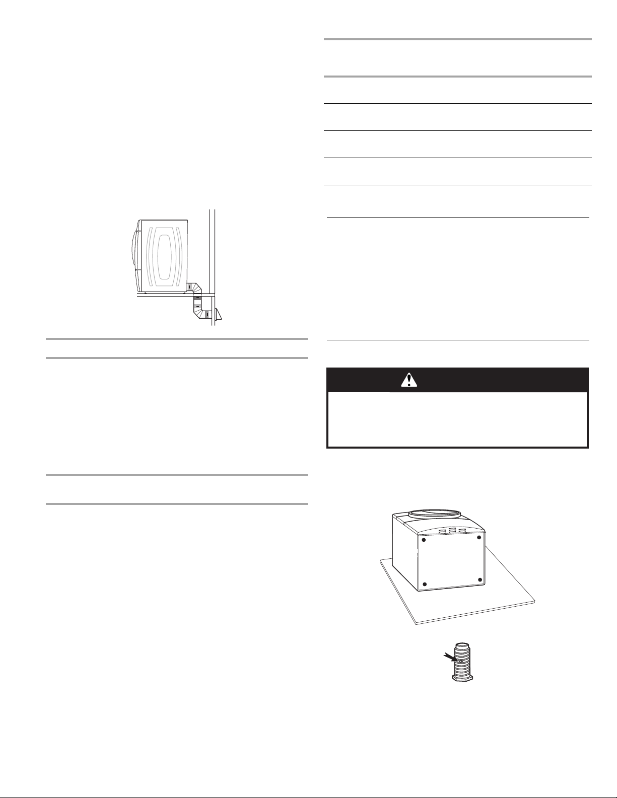
Install Leveling Legs
WARNING
Excessive Weight Hazard
Use two or more people to move and install dryer.
Failure to do so can result in back or other injury.
1. To protect the floor, use a large flat piece of cardboard from
the dryer carton. Place cardboard under the entire back edge
of the dryer.
2. Firmly grasp the body of the dryer (not the console panel).
Gently lay the dryer on the cardboard. See illustration.
3. Examine the leveling legs. Find the diamond marking.
4. Screw the legs into the leg holes by hand. Use a wrench to
finish turning the legs until the diamond marking is no longer
visible.
5. Place a carton corner post from dryer packaging under each
of the 2 dryer back corners. Stand the dryer up. Slide the
dryer on the corner posts until it is close to its final location.
Leave enough room to connect the exhaust vent.
10
Connect Vent
C
1. Using a 4" (10.2 cm) clamp, connect vent to exhaust outlet in
dryer. If connecting to existing vent, make sure the vent is
clean. The dryer vent must fit over the dryer exhaust outlet
and inside the exhaust hood. Check that the vent is secured
to exhaust hood with a 4" (10.2 cm) clamp.
2. Move dryer into its final location. Do not crush or kink vent.
3. (On gas models) Check that there are no kinks in the flexible
gas line.
4. Once the exhaust vent connection is made, remove the
corner posts and cardboard.
Level Dryer
Check the levelness of the dryer. Check levelness first side to
side, then front to back.
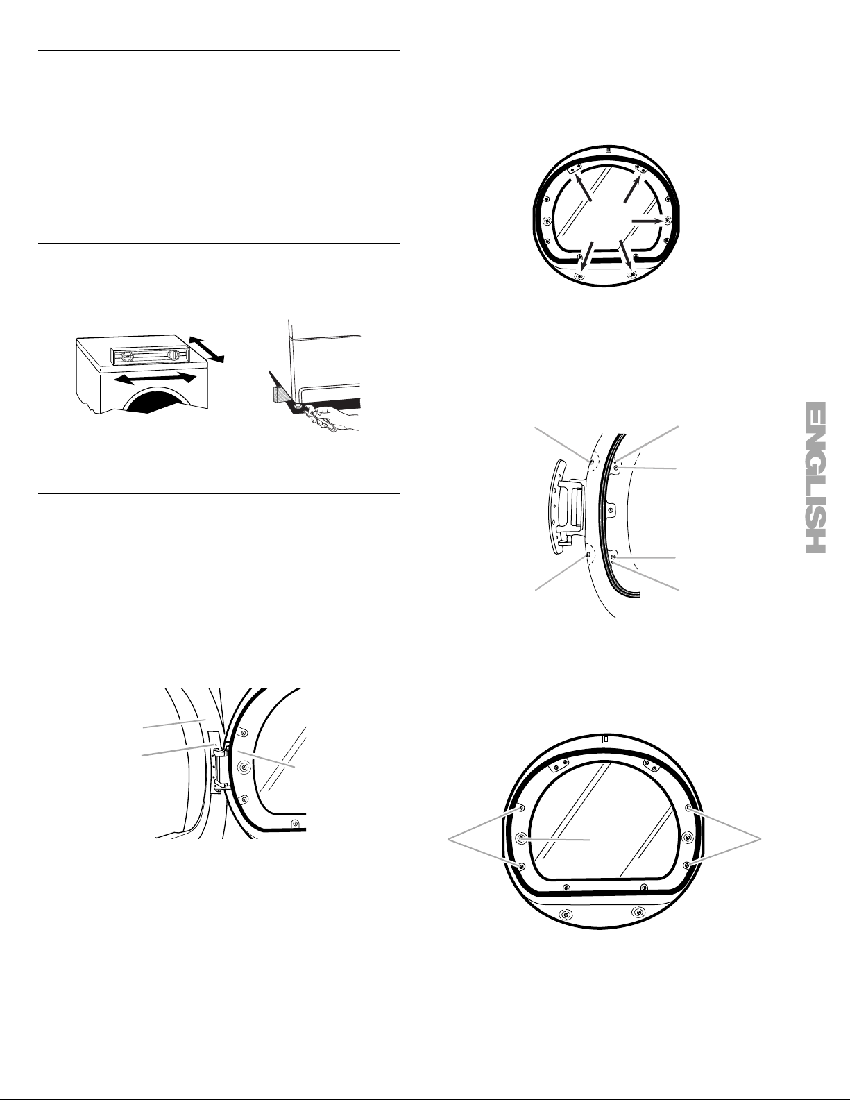
4. Lay the dryer door on a flat, protected surface with the inside
door assembly facing up.
Remove the 5 screws to release the outer door assembly
from the inner door assembly, as indicated below. See
illustration. It is important that you remove only the
5 indicated screws.
5. Lift the inner door assembly off of the outer door assembly.
Set the outer door assembly aside.
Reverse the hinge
1. Place the inner door, screw head side up, on the work space.
2. Remove the 4 hinge screws that hold the hinge to the door
and remove hinge.
If the dryer is not level, prop up the dryer using a wood block.
Use a wrench to adjust the legs up or down and check again for
levelness.
Reverse Door Swing
You can change your door swing from a right-side opening to a
left-side opening, if desired.
NOTE: For ease of installation, you may want to use 2 or more
people to remove and reattach the dryer door.
Remove the door
1. Place a towel or soft cloth on top of the dryer or work space
to protect the surface.
2. Open the dryer door. Remove the 5 screws that hold the door
hinge on the front panel of the dryer.
A
C
B
A
B
C
C
A
A. Hinge side screw
B. Locator pins on hinge
C. Top side screw
3. Move the large hole screw to the opposite side. Remove the
2 plug screws and plastic plugs, and insert them in the
original screw holes on the opposite side.
B
3. Remove the door.
A. Dryer front panel
B. Dryer door
C. Screws
A
A. Hinge screws
B. Large hole screw
C. Plug screws and plastic plugs
B
11
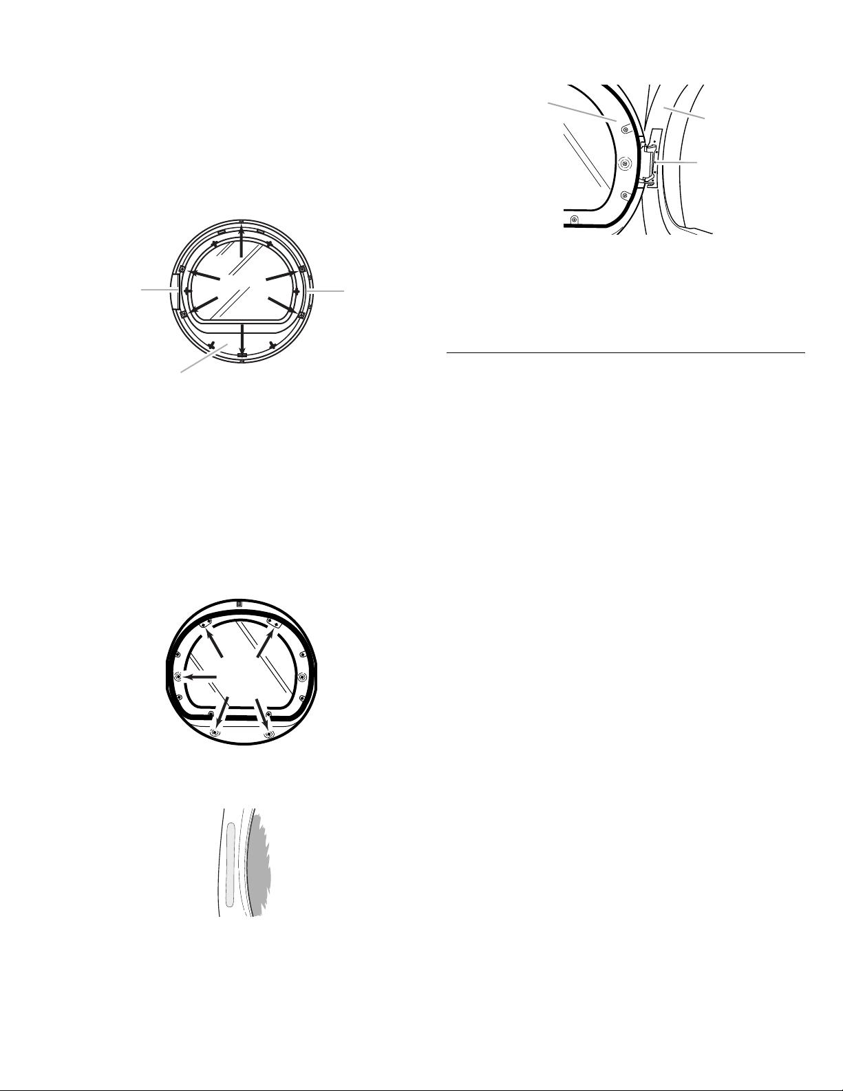
4. Move hinge to the other side and reattach with the 4 screws
C
B
removed in Step 2. Make sure locator pins line up in holes
and drive the top 2 screws in place first to help drive locator
pins into proper location.
5. Set the inner door assembly aside.
Reverse the door handle
1. Place the outer door assembly face down on work space.
2. Remove the 6 screws that hold the intermediate door to the
outer door assembly. Remove the intermediate door, and set
hinge shield aside. Remove the hinge hole cover.
B
NOTE: Two or more people may be needed to reattach the
dryer door.
A
C
A. Dryer door
B. Dryer front panel
C. Insert this hinge screw first.
5. Close the door and check that it latches securely.
6. Check for fingerprints on the glass. Clean the glass if
necessary.
A
A. Intermediate door
B. Hinge shield
C. Hinge hole cover
3. Rotate the window assembly 180º and reattach the
intermediate door, hinge shield and hinge hole cover with the
6 screws removed in Step 2.
Reinstalling the door
1. Place the inner door assembly into the outer door assembly.
To fit correctly, the inside door assembly edge is completely
inside the outside door assembly edge.
2. Reassemble the inner and outer door assemblies with the
5screws.
3. Remove existing label from the opposite side of the door and
discard. Find label provided with the Use and Care Guide and
apply over original hinge holes.
4. Align the door by placing the locating tabs on the hinge with
the locating holes on the dryer front panel. Insert and tighten
the center hinge screw. The door will hang in place while you
insert and tighten the remaining 4 screws.
Complete Installation
1. Check that all parts are now installed. If there is an extra part,
go back through the steps to see which step was skipped.
2. Check that you have all of your tools.
3. Dispose of/recycle all packaging materials.
4. Check the dryer’s final location. Be sure the vent is not
crushed or kinked.
5. Check that the dryer is level. See “Level Dryer.”
6. Plug into a grounded 4 prong outlet. Turn on power.
7. Remove any protective film or tape remaining on the dryer.
8. Read “Dryer Use.”
9. Wipe the dryer drum interior thoroughly with a damp cloth to
remove any dust.
10. Select a Timed Dry heated cycle, and start the dryer. Do not
select the Air Dry Temperature setting.
If the dryer will not start, check the following:
■ Controls are set in a running or “On” position.
■ Start button has been pushed firmly.
■ Dryer is plugged into a grounded outlet.
■ Electrical supply is connected.
■ Household fuse is intact and tight, or circuit breaker has
not tripped.
■ Dryer door is closed.
This dryer automatically runs an installation diagnostic routine at
the start of its first cycle.
If you receive an L2 code, there may be a problem with your
home power supply keeping the dryer’s heater from turning
on. See “Troubleshooting.”
If you receive an AF code, your dryer vent may be crushed or
blocked. See “Troubleshooting.”
NOTE: You may notice an odor when the dryer is first heated.
This odor is common when the heating element is first used. The
odor will go away.
12
DRYER USE
Starting Your Dryer
WARNING
Explosion Hazard
Keep flammable materials and vapors, such as
gasoline, away from dryer.
Do not dry anything that has ever had anything
flammable on it (even after washing).
Failure to follow these instructions can result in death,
explosion, or fire.
WARNING: To reduce the risk of fire, electric shock, or injury to
persons, read the IMPORTANT SAFETY INSTRUCTIONS before
operating this appliance.
Follow these basic steps to start your dryer. Please refer to
specific sections of this manual for more detailed information.
1. Clean lint screen before each load. See “Cleaning the Lint
Screen.”
2. Place laundry in dryer and shut door.
3. Press the POWER button. Then rotate the dial or press a
Timed Cycles button to select the desired Auto or Timed
Cycle. The indicator light for the selected Auto or Timed cycle
will glow green. The preset modifiers for the selected cycle
will glow green. Selectable options will glow amber. If an
option or modifier is unavailable with the selected cycle, the
light will not illuminate. The estimated or actual cycle time (in
minutes) will show in the display.
To use an Auto Cycle
NOTE: A light next to each feature will glow green when the
feature is selected or will glow amber when the feature is
selectable. The light will not glow when the selection is
unavailable with the cycle or option combinations selected.
■ Select an Auto Cycle.
WARNING
Fire Hazard
No washer can completely remove oil.
Do not dry anything that has ever had any type of oil on
it (including cooking oils).
Items containing foam, rubber, or plastic must be dried
on a clothesline or by using an Air Cycle.
Failure to follow these instructions can result in death
or fire.
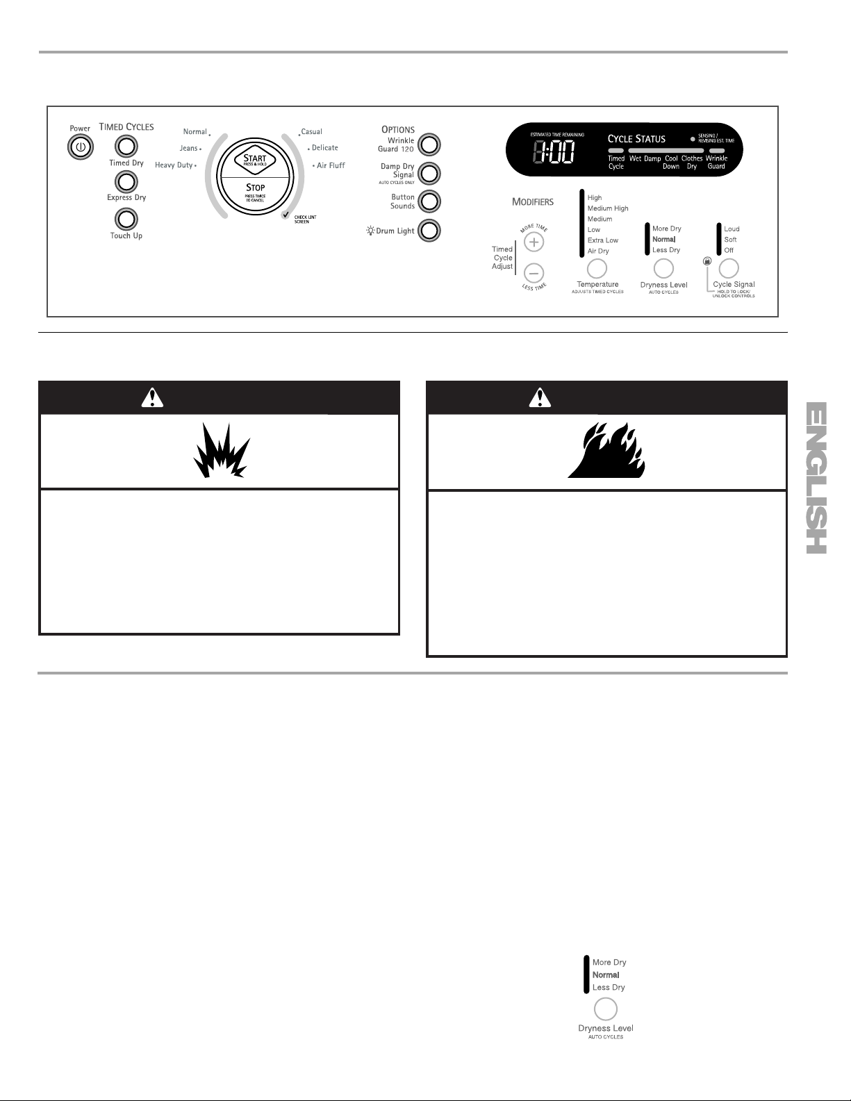
■ Select DRYNESS LEVEL to adjust how dry you want the
load. As the cycle runs, the control senses the dryness of
the load and adjusts the time automatically for the
selected dryness level.
NOTE: Most loads may be dried using Normal dryness
level, which is shown in bold letters on your control panel.
Normal is the energy preferred dryness level and will use
the least energy.
■ Select the desired Options.
To make changes during an Auto Cycle:
■ Press STOP once.
■ Adjust Dryness Level.
NOTE: Dryness Level selections can be made only while
using Auto Cycles. You can select a different dryness
level, depending on your load, by pressing Dryness Level
and choosing More Dry, Normal or Less Dry. Selecting
More Dry, Normal or Less Dry automatically adjusts the
sensed time needed.
13

How Auto Dry works
SmartHeat™ improves drying performance with Auto Moisture
Sensing Plus, which advances the cycle as moisture is extracted
from clothing. A thermistor (electronic temperature sensor) and
moisture sensing strips in the dryer drum help measure the
amount of moisture in the clothes as they tumble. An electronic
control determines the load type to help save time, avoid
overdrying, and increase the accuracy of the end dryness level.
After the first 5 minutes of an automatic cycle, the estimated time
display will adjust based on the approximate load size, cycle,
dryness level selected and amount of moisture left in the clothes.
When the clothes have reached approximately 80% of the
dryness level selected, the estimated time display will adjust
again, showing the final drying time. Auto Moisture Sensing Plus
takes the guesswork out of drying time and enhances fabric care.
To use a Timed Cycle
NOTE: A light next to each feature will glow green when the
feature is selected or will glow amber when the feature is
selectable. The light will not glow when the selection is
unavailable with the cycle or option combinations selected.
■ Press a Timed Cycles button or, to select Air Fluff, rotate
the control knob to the desired cycle.
■ Press MORE TIME or LESS TIME until the desired drying
time is displayed. Tap MORE TIME or LESS TIME, and the
time will change by 1-minute intervals. Press and hold
MORE TIME or LESS TIME, and the time will change by
5-minute intervals.
NOTE: The More Time and Less Time buttons can be
used only with Timed Cycles.
■ Press TEMPERATURE until the desired temperature
glows.
NOTE: During a Timed Cycle, you can change the settings for
Time, Temperature, WRINKLE GUARD
®
and End of Cycle
Signal. Press STOP twice to stop the dryer and clear the
settings. Select another cycle or option.
4. (OPTIONAL STEP) If desired, select OPTIONS. For more
details, see “Options.”
5. (OPTIONAL STEP) If desired, set the
End of Cycle Signal
.
Select LOUD or SOFT by pressing the Cycle Signal button to
alert you when a cycle ends.
6. Press and hold START for approximately 3 seconds until
dryer starts. Be sure the door is closed.
■ If you do not press Start within 5 minutes of selecting the
cycle, the dryer automatically shuts off.
■ If you wish to end your drying cycle after pressing Start,
press Stop twice.
Stopping Your Dryer
To stop your dryer at any time
Press STOP twice or open the door.
Pausing or Restarting
To pause the dryer at any time
Open the door or press STOP once.
To restart the dryer
Close the door. Press and hold START until dryer starts.
NOTE: Drying will continue from where the cycle was interrupted
if you close the door and press START within 5 minutes. If the
cycle is interrupted for more than 5 minutes, the dryer will shut
off. Select new cycle settings before restarting the dryer.
Control Locked
This feature allows you to lock your settings to avoid unintended
use of the dryer. You can also use the Control Locked feature to
avoid unintended cycle or option changes during dryer operation.
To enable the Control Locked feature:
Press and hold CYCLE SIGNAL for 3 seconds. The Control
Locked indicator light glows, and a single beep tone is heard. To
unlock, press and hold CYCLE SIGNAL for 3 seconds. The
indicator light turns off.
Drying and Cycle Tips
Select the correct cycle and dryness level or temperature for your
load. If an Auto Cycle is running, the display shows the estimated
cycle time, which is determined by your dryer automatically
sensing the dryness level of your load. If a Timed Cycle or
SteamCare Cycle is running, the display shows the exact number
of minutes remaining in the cycle.
Cool Down tumbles the load without heat during the last few
minutes of all cycles. Cool Down makes the loads easier to
handle and reduces wrinkling. The length of the Cool Down
depends on the load size and dryness level.
Drying tips
■ Follow care label directions when they are available.
■ If desired, add a fabric softener sheet. Follow package
instructions.
■ To reduce wrinkling, remove the load from the dryer as soon
as tumbling stops. This is especially important for permanent
press, knits and synthetic fabrics.
■ Avoid drying heavy work clothes together with lighter fabrics.
This could cause overdrying of lighter fabrics and lead to
increased shrinkage or wrinkling.
Cycle tips
■ Dry most loads using the preset cycle settings.
■ Refer to the Auto, Timed or SteamCare Cycles Preset
Settings chart (in the “Cycles” section) for a guide to drying
various loads.
■ Drying temperature and Dryness Level are preset when
you choose an Auto Cycle. You can select a different
dryness level, depending on your load, by pressing
Dryness Level and choosing More Dry, Normal or Less
Dry.
NOTE: You cannot use the Timed Cycle Adjust and you
cannot modify temperature with the Auto Cycles.
■ If you wish to adjust the cycle length of a Timed Cycle,
press More Time or Less Time. Adjust the temperature of
a Timed Cycle by pressing TEMPERATURE until the
desired temperature is selected.
NOTE: You cannot use the Dryness Level with Timed or
SteamCare Cycles.
14
 Loading...