

Kenmore 110.C6808*, 110.C6809* Owner's Manual
®
Electric Dryer
Use & Care Guide
Sécheuse électrique
Guide d'utilisation et d'entretien
Models/Modèles 110.C6808✼, C6809✼
✼ = color number/numéro de couleur
W10164638B Sears Canada Inc., Toronto, Ontario, Canada M5B 2B8 www.sears.ca

TABLE OF CONTENTS
WARRANTY.....................................................................................2
DRYER SAFETY..............................................................................3
INSTALLATION INSTRUCTIONS ..................................................4
Tools and Parts ............................................................................4
Location Requirements ...............................................................5
Electrical Requirements................................................................6
Venting Requirements..................................................................6
Plan Vent System .........................................................................7
Install Vent System.......................................................................9
Install Leveling Legs .....................................................................9
Connect Vent................................................................................9
Connect Inlet Hose.......................................................................9
Level Dryer................................................................................. 10
Reverse Door Swing.................................................................. 10
Complete Installation................................................................. 11
DRYER USE ................................................................................. 12
Starting Your Dryer.................................................................... 12
Stopping, Pausing, or Restarting .............................................. 14
Drying and Cycle Tips ............................................................... 14
Status Lights.............................................................................. 14
KENMORE ELITE® APPLIANCE WARRANTY
ONE YEAR LIMITED WARRANTY
When installed, operated and maintained according to all
instructions supplied with the product, if this appliance fails due
to a defect in material or workmanship within one year from the
date of purchase, call 1-800-4-MY-HOME
repair.
If this appliance is used for other than private family purposes, this warranty applies for only 90 days from the date of purchase.
THIS WARRANTY COVERS ONLY DEFECTS IN MATERIAL
AND WORKMANSHIP. SEARS WILL NOT PAY FOR:
1. Expendable items that can wear out from normal use,
including but not limited to filters, belts, light bulbs, and bags.
2. A service technician to instruct the user in correct product
installation, operation or maintenance.
3. A service technician to clean or maintain this product.
4. Damage to or failure of this product if it is not installed,
operated or maintained according to all instructions supplied
with the product.
5. Damage to or failure of this product resulting from accident,
abuse, misuse or use for other than its intended purpose.
6. Damage to or failure of this product caused by the use of
detergents, cleaners, chemicals or utensils other than those
recommended in all instructions supplied with the product.
®
to arrange for free
Cycles ........................................................................................ 15
Modifiers .................................................................................... 16
Options ...................................................................................... 16
Cycle Signal............................................................................... 17
Changing Cycles, Modifiers, and Options ................................ 17
Drying Rack ............................................................................... 17
DRYER CARE............................................................................... 18
Cleaning the Dryer Location...................................................... 18
Cleaning the Lint Screen ........................................................... 18
Cleaning the Dryer Interior......................................................... 19
Removing Accumulated Lint ..................................................... 19
Water Inlet Hoses ...................................................................... 19
Vacation, Storage, and Moving Care ........................................ 19
Changing the Drum Light .......................................................... 20
TROUBLESHOOTING.................................................................. 20
Dryer Operation ......................................................................... 20
Dryer Results ............................................................................. 21
PROTECTION AGREEMENTS.................................................... 22
SERVICE NUMBERS ...............................................BACK COVER
7. Damage to or failure of parts or systems resulting from
unauthorized modifications made to this product.
DISCLAIMER OF IMPLIED WARRANTIES; LIMITATION OF
REMEDIES
Customer’s sole and exclusive remedy under this limited
warranty shall be product repair as provided herein. Implied
warranties, including warranties of merchantability or fitness for a
particular purpose, are limited to one year or the shortest period
allowed by law. Sears shall not be liable for incidental or
consequential damages. Some states and provinces do not allow
the exclusion or limitation of incidental or consequential
damages, or limitations on the duration of implied warranties of
merchantability or fitness, so these exclusions or limitations may
not apply to you.
This warranty applies only while this appliance is used in the United States and Canada.
This warranty gives you specific legal rights, and you may also have other rights which vary from state to state.
Sears, Roebuck and Co.
Dept. 817WA, Hoffman Estates, IL 60179
Sears Canada Inc.
Toronto, Ontario, Canada M5B 2B8
2

DRYER SAFETY
Your safety and the safety of others are very important.
We have provided many important safety messages in this manual and on your appliance. Always read and obey all safety
messages.
This is the safety alert symbol.
This symbol alerts you to potential hazards that can kill or hurt you and others.
All safety messages will follow the safety alert symbol and either the word “DANGER” or “WARNING.”
These words mean:
You can be killed or seriously injured if you don't immediately
DANGER
WARNING
All safety messages will tell you what the potential hazard is, tell you how to reduce the chance of injury, and tell you what can
happen if the instructions are not followed.
follow instructions.
can be killed or seriously injured if you don't
You
instructions.
follow
3

INSTALLATION INSTRUCTIONS
Tools a nd Parts
Gather the required tools and parts before starting installation. Read and follow the instructions provided with any tools listed here.
Parts supplied:
Remove parts package from dryer drum. Check that all parts were included.
■ Flat-blade screwdriver
■ #2 Phillips screwdriver
■ Adjustable wrench that
opens to 1" (25 mm) or
hex-head socket wrench
adjusting dryer feet)
(for
■ Tin snips (new vent
installations)
4
■ Level
■ Vent clamps
■ Caulking gun and
compound (for installing
new exhaust vent)
■ Tap e me asu re
A
B
C
A. Leveling legs (4)
B. “Y” connector
C. Short inlet hose
D. Long inlet hose
E. Rubber washer
D
E

Parts needed:
Check local codes, check existing electrical supply, and venting and see “Electrical Requirements” and “Venting Requirements” before purchasing parts.
Mobile home installations require
metal exhaust system hardware
available for purchase from your local Sears store or Sears
Service Center. For further information, please call 1-800-4-MY-
®
HOME
(1-800-469-4663).
Location Requirements
You will need
■ A location that allows for proper exhaust installation. See
“Venting Requirements.”
■ A separate 30-amp circuit.
■ A grounded electrical outlet located within 2 ft (610 mm) of
either side of the dryer. See “Electrical Requirements.”
■ A sturdy floor to support the total weight (dryer and load) of
200 lbs (90.7 kg). The combined weight of a companion
appliance should also be considered.
■ Cold water faucets located within 4 ft (1.2 m) of the water fill
valves, and water pressure of 20-100 psi (138-690 kPa). You
may use the water supply for your washer using the “Y”
connector and short hose (if needed) which are provided.
■ 20-100 psi (138-690 kPa) for best performance.
■ A level floor with a maximum slope of 1" (25 mm) under entire
dryer.
Do not operate your dryer at temperatur
lower temperatures, the dryer might not shut off at the end of an
automatic cycle. Drying times can be extended.
The dryer must not be installed or st
be exposed to water and/or weather.
Check code requirements. Some cod
installation of the dryer in garages, closets, mobile homes or
sleeping quarters. Contact your local building inspector.
Installation Clearances
The location must be large enough to allow the dryer door to open fully.
es below 45ºF (7ºC). At
ored in an area where it will
es limit, or do not permit,
Dryer Dimensions
1
43
/2"
(1105 mm)
1
/4"
1
29
/4"
(743 mm)
29"
(737 mm)
22
(565 mm)
*Most installations require a minimum 5" (127 mm) clearance
behind the dryer for the exhaust vent with elbow. See “Venting
Requirements.”
Installation spacing for recessed area or closet installation
The following spacing dimensions are recommended for this
dryer. This dryer has been tested for spacing of 0" (0 mm)
cl
earance on the sides and rear. Recommended spacing should
be considered for the following reasons:
■ Additional spacing should be considered for ease of
installation and servicing.
■ Additional clearances might be required for wall, door and
floor moldings.
■ Additional spacing should be considered on all sides of the
dryer to reduce noise transfer.
■ For closet installation, with a door, minimum ventilation
openings in the top and bottom of the door are required.
Louvered doors with equivalent ventilation openings are
acceptable.
■ Companion appliance spacing should also be considered.
■ Additional spacing is required if you exhaust out the rear of
the dryer to either the right or left side.
14" máx.*
18"*
(457 mm)
1"
(25 mm)
29"
(737 mm)
A
(356 mm)
1"
(25 mm)
A. Recessed area
B. Side view - closet or confined area
C. Closet door with vents
1
/4"
29
(743 mm)
B
48 in.2*
(310 cm2)
2
24 in.
*
2
(155 cm
)
5"
(127 mm)
3"*
(76 mm)
3"*
(76 mm)
C
*Required spacing
Mobile Home - Additional Installation Requirements
This dryer is suitable for mobile home installations.
The installation must conform to the Canadian Manufactured
Home Standar
Mobile home installations require:
■ Metal exhaust system hardware, which is available for
purchase from your local Sears store or Sears Service Center.
■ Special provisions must be made in mobile homes to
introduce outside air into the dryer. The opening (such as a
nearby window) should be at least twice as large as the dryer
exhaust opening.
d, CAN/CSA Z240 MH.
5

Electrical Requirements
Part Number 3394208.
1-800-4-MY-HOME®
For further information, please call
(1-800-469-4663).
WARNING
Electrical Shock Hazard
Plug into a grounded 4 prong outlet.
Failure to do so can result in death or electrical shock.
It is your responsibility
■ To contact a qualified electrical installer.
■ To be sure that the electrical connection is adequate and in
conformance with the Canadian Electrical Code, C22.1-latest
edition and all local codes. A copy of the above codes
standard may be obtained from: Canadian Standards
Association, 178 Rexdale Blvd., Toronto, ON M9W 1R3
Canada.
■ To supply the required 4 wire, single phase, 120/240 volt,
60 Hz., AC only electrical supp
circuit, fused on both sides of the line. A time-delay fuse or
circuit breaker is recommended. Connect to an individual
branch circuit.
■ This dryer is equipped with a CSA International Certified
Power Cord intended to be plugged into a standard 14-30R
wall receptacle. The cord is 5 ft (1.52 m) in length. Be sure
wall receptacle is within reach of dryer’s final location.
ly on a separate 30-amp
GROUNDING INSTRUCTIONS
■
For a grounded, cord-connected dryer:
This dryer must be grounded. In the event of malfunction or
breakdown, grounding will reduce the risk of electric shock
by providing a path of least resistance for electric current.
This dryer is equipped with a cord having an equipmentgrounding conductor and a grounding plug. The plug must
be plugged into an appropriate outlet that is properly
installed and grounded in accordance with all local codes
and ordinances.
WARNING: Improper connection of the equipment-
grounding conductor can result in a risk of electric shock.
Check with a qualied electrician or service representative
or personnel if you are in doubt as to whether the dryer is
properly grounded. Do not modify the plug provided with
the dryer: if it will not t the outlet, have a proper outlet
installed by a qualied electrician.
SAVE THESE INSTRUCTIONS
Venting Requirements
WARNING
4-wire receptacle 14-30R
■ Do not use an extension cord.
If you are using a replacement power supply cord, it is
ecommended that you use Power Supply Cord Replacement
r
Fire Hazard
Use a heavy metal vent.
Do not use a plastic vent.
Do not use a metal foil vent.
Failure to follow these instructions can result in death
or re.
WARNING: To reduce the risk of fire, this dryer MUST BE
EXHAUSTED OUTDOORS.
IMPORTANT: Obse
The dryer exhaust must not be connected into any gas vent,
imney, wall, ceiling, attic, crawlspace, or a concealed space of
ch
a building.
If using an existing vent system
■ Clean lint from the entire length of the system and make sure
exhaust hood is not plugged with lint.
■ Replace any plastic or metal foil vent with rigid heavy metal
vent or flexible metal vent.
■ Review Vent system chart. Modify existing vent system if
necessary to achieve the best drying performance. Only rigid
or flexible metal vent shall be used for exhausting.
rve all governing codes and ordinances.
6

If this is a new vent system
A
Vent material
■ Use a heavy metal vent. Do not use plastic or metal foil vent.
■ 4" (102 mm) heavy metal exhaust vent and clamps must be
used. DURASAFE™ venting products are recommended.
4" (102 mm) heavy metal exhaust vent
DURASAFE™ vent products can be purchased from your
dealer. For further information, please call
1-800-4-MY-HOME® (1-800-469-4663) or visit our website at
www.sears.com or www.sears.ca.
Rigid metal vent
■ For best drying performance, rigid metal vents are
recommended.
■ Rigid metal vent is recommended to avoid crushing and
kinking.
Flexible metal vent
■ Flexible metal vents are acceptable only if accessible for
cleaning.
■ Flexible metal vent must be fully extended and supported
when the dryer is in its final location.
■ Remove excess flexible metal vent to avoid sagging and
kinking that may result in reduced airflow and poor
performance.
■ Do not install flexible metal vent in enclosed walls, ceilings,
or floors.
■ The total length of flexible metal vent should not exceed
7¾ ft (2.4 m).
Elbows
45° elbows provide better airflow than 90° elbows.
Exhaust
Recommended hood styles are shown here.
B
A
4"
(102 mm)
4"
(102 mm)
A. Louvered hood style
B. Box hood style
The angled hood style (shown here) is acceptable.
4"
(102 mm)
■ An exhaust hood should cap the vent to keep rodents and
C
2½"
(64 mm)
insects from entering the home.
■ Exhaust hood must be at least 12" (305 mm) from the ground
or any object that may be in the path of the exhaust (such as
flowers, rocks or bushes, snow line, etc.).
■ Do not use an exhaust hood with a magnetic latch.
Improper venting can cause moisture and lint to collect
indoors, which may result in:
Moisture damage to woodwork, furniture, paint, wallpaper,
carpets, etc.
Housecleaning problems and health problems.
Plan Vent System
Good Better
Clamps
■ Use clamps to seal all joints.
■ Exhaust vent must not be connected or secured with screws
or other fastening devices that extend into the interior of the
vent and catch lint. Do not use duct tape.
Clamp
Choose your exhaust installation type
Recommended exhaust installations
Typical installations vent the dryer from the rear of the dryer. Other installations are possible.
B
C
D
E
F
G
B
H
A. Dryer
B. Elbow
C. Wall
D. Exhaust hood
E. Clamps
F. Rigid metal or flexible metal vent
G. Vent length necessar
H. Exhaust outlet
y to connect elbows
7

Optional exhaust installations
Venting systems come in many varieties. Select the type best for your installation.
■ Over-the-top installation:
Part Number 26-49900
Special provisions for mobile home installations
The exhaust vent must be securely fa
stened to a noncombustible
portion of the mobile home structure and must not terminate
beneath the mobile home. Terminate the exhaust vent outside.
This dryer can be converted to exhaust out the bottom. If you
prefer, you may contact your local dealer to have the dryer
converted. This dryer can also be exhausted from the rear to
either the right or left side. Optional kits for these exhaust
installations are needed. Refer to the manufacturer’s instructions
for kit installation instructions.
A B
A. Standard rear offset exhaust installation
B. Rear exhaust installation to right side (Part Number
C. Bottom exhaust installation
D. Over-the-top installation (also available with one
04) or left side (Part Numbers 8544761 and
82125
8212504).
C
o
ffset elbow)
D
NOTE: The following kits for alternate installations are available
for purchase. For further information, please call
1-800-4-MY-HOME
■ Rear exhaust installation to right side:
®
(1-800-469-4663).
Part Number 8212504
■ Rear exhaust installation to left side:
Part Number 8544761 and 8212504
■ Bottom exhaust installation:
Part Number 8212503
Determine vent path
■ Select the route that will provide the straightest and most
direct path outdoors.
■ Plan the installation to use the fewest number of elbows and
turns.
■ When using elbows or making turns, allow as much room as
possible.
■ Bend vent gradually to avoid kinking.
■ Use the fewest 90° turns possible.
Determine vent length and elbows needed for best drying performance
■ Use the following Vent system chart to determine type of vent
material and hood combinations acceptable to use.
NOTE:
Do not use vent runs longer than those specified in
the Vent system chart. Exhaust systems longer than those
specified will:
■ Shorten the life of the dryer.
■ Reduce performance, resulting in longer drying times and
increased energy usage.
The Vent system chart provides venting requirements that will help to achieve the best drying performance.
Vent system chart
NOTE: Bottom exhaust performance is equivalent to adding two
elbows. To determine maximum exhaust length, add two elbows
to the chart.
NOTE:
equivalent to adding one elbow. To determine maximum exhaust
length, add one elbow to the chart.
Performance of rear exhaust to either side of the dryer is
Number of
90
º turns
or elbows
Type of
vent
Box or
Louvered
hoods
0 Rigid metal 200 ft (61 m) 185 ft (56.4 m)
1 Rigid metal 190 ft (58 m) 175 ft (53.3 m)
2 Rigid metal 180 ft (55 m) 165 ft (50.3 m)
3 Rigid metal 170 ft (51.8 m) 155 ft (47.2 m)
4 Rigid metal 160 ft (48.8 m) 145 ft (44.2 m)
Angled
hoods
8

Install Vent System
1. Install exhaust hood. Use caulking compound to seal exterior
wall opening around exhaust hood.
onnect vent to exhaust hood. Vent must fit inside exhaust
2. C
hood. Secure vent to exhaust hood with 4" (102 mm) clamp.
3. Ru
n vent to dryer location. Use the straightest path possible.
See “Determine vent path” in “Plan Vent System.” Avoid 90º
turns. Use clamps to seal all joints. Do not use duct tape,
screws, or other fastening devices that extend into the
interior of the vent to secure vent, which can catch lint.
Install Leveling Legs
WARNING
Excessive Weight Hazard
Use two or more people to move and install dryer.
Failure to do so can result in back or other injury.
1. To avoid damaging the floor, use a large, flat piece of
cardboard from the dryer carton. Place cardboard under the
entire back edge of the dryer.
2. Firmly
grasp the body of the dryer (not the top or console
panel). Gently lay the dryer on the cardboard. See illustration.
2. Remove old rubber washer from inlet hose and replace with
new rubber washer provided. If space permits, attach the
brass female end of the “Y” connector to the cold water
faucet.
NOTE: If “Y” con
faucet, go to Step 6. If “Y” connector cannot be attached
directly to the cold water faucet, the short hose must be
used. Continue with Step 3.
3. Attach short hose to cold water faucet. Screw on coupling by
hand until it is seated on faucet.
4. Using pliers, tighten the couplings with an additional two-
thirds turn.
NOTE:
Do not overtighten. Damage to the coupling can
result.
5. Attach “Y” connector to brass male end of small hose. Screw
on coupling by hand until it is seated on connector.
6. One end of the
coupling. Attach this end to the “Y” connector.
7. Attach washer cold inlet hose to other end of “Y” connector.
Screw on coupling by hand until it is seated on connector.
8. Usin
g pliers, tighten the couplings with an additional
two-thirds turn.
nector can be attached directly to cold water
long hose has a wire mesh strainer inside the
3. Examine the leveling legs. Find the diamond marking.
4. Screw the legs into the leg holes by hand. Use a wrench to
finish turning the legs until the diamond marking is no longer
visible.
5. Plac
e a carton corner post from dryer packaging under each
of the 2 dryer back corners. Stand the dryer up. Slide the
dryer on the corner posts until it is close to its final location.
Leave enough room to connect the exhaust vent.
Connect Vent
1. Using a 4" (102 mm) clamp, connect vent to exhaust outlet in
dryer. If connecting to existing vent, make sure the vent is
clean. The dryer vent must fit over the dryer exhaust outlet
and inside the exhaust hood. Check that the vent is secured
to exhaust hood with a 4" (102 mm) clamp.
2. Move dryer
3. Once the exhaust vent connection is made, remove the
corner posts and cardboard.
into its final location. Do not crush or kink vent.
Connect Inlet Hose
The dryer must be connected to the cold water faucet using the new inlet hoses. Do not use old hoses.
1. Turn cold water faucet off and remove washer inlet hose.
A
A. Inlet to cold water
NOTE: Do not overtighten. Damage to the coupling can result.
9. Attach
other end of long hose to fill valve at bottom of dryer
back panel. Screw on coupling by hand until it is seated on fill
valve connector.
9

10. Using pliers, tighten the coupling with an additional two-
thirds turn.
NOTE: Do not overtighten. Damage to the coupling can result.
11. Check that the water faucets are on.
12. Check for leaks around “Y” connector, faucet, and hoses.
Level Dryer
Check the levelness of the dryer. Check levelness first side to side, then front to back.
3. Loosen the top scr
4. Remove the dryer door and the hinges by lifting upward on
the door. Lay the door on a flat, protected surface, with the
inside of the door facing up. Remove remaining 2 loose
screws from dryer front panel.
5. Remove the 4 plastic plugs located outside the dryer door
opening.
ew from each of the 2 hinges in Step 2.
A
B
A
B
A. Loosen these screws.
B. Remove these screws.
If the dryer is not level, prop up the dryer using a wood block. Use a wrench to adjust the legs up or down and check again for levelness.
Reverse Door Swing
You can change your door swing from a right-side opening to a left-side opening, if desired.
1. Place a
to avoid damaging the surface.
Remove the door assembly
1. Op
2. Re
attach the dryer door to the front panel of the dryer.
towel or soft cloth on top of the dryer or work space
en the dryer door.
move the bottom screw from each of the 2 hinges that
6. Install 4 plastic plugs into screw holes in the dryer left where
the hinges were removed in Step 4.
Reverse the strike
1. Remove the
door strike from the dryer door opening.
10

2. Remove the cosmetic screw opposite the door strike.
A
A
B
A. Door strike
B. Cosmetic screw
3. Reinstall the door strike and cosmetic screw on the opposite
side of the dryer door opening from where they were
removed.
NOTE:
Door strike and plugs must be on the same side of the
dryer door opening.
Reinstall the door
1. Remove the 4 screws and 2 hinges from the dryer door.
place the 4 screws in the same holes.
2. Re
5. Insta
ll screws in the top hinge holes in the door. Do not
tighten screws. Leave approximately ¼" (5 mm) of screw
exposed.
A
A. Install these screws first.
6. Hang door by placing screw heads into top slotted holes of
hinges and slide door down. Align bottom screw holes in
hinge and door. Install two bottom screws. Tighten all hinge
screws.
3. Remove the 4 screws from the opposite side of the door.
4. Install the 2 hinges to the front panel of the dryer using
4 screws. Use the non-slotted side to attach the hinge to the
fr
ont panel.
7. Close door to engage door strike.
Complete Installation
1. Check that all parts are now installed. If there is an extra part,
go back through the steps to see which step was skipped.
2. C
heck that you have all of your tools.
spose of/recycle all packaging materials.
3. Di
sure the water faucets are on.
4. Be
5. Che
6. Check the dryer’s final location. Be sure the vent is not
7. Che
8. Plug
9. Remove any film
10. R
ck for leaks around “Y” connector, faucet, and hoses.
crushed or kinked.
ck that the dryer is level. See “Level Dryer.”
into a grounded 4 prong outlet. Turn on power.
or tape remaining on the dryer.
NOTE: Glass door
models have a film on the window that
should be removed.
ead “Dryer Use.”
11

11. Wipe the dryer drum interior thoroughly with a damp cloth to
remove any dust.
12. If you
13. Test dryer operation by selecting a Timed Dry heated cycle
live in a hard water area, use of a water softener is
recommended to control the buildup of scale through the
water system in the dryer. Over time, the buildup of lime scale
may clog different parts of the water system, which will
reduce product performance. Excessive scale buildup may
lead to the need for certain part replacement or repair.
and starting the dryer. For this test, do not select the Air Only
modifier.
If the dryer will not start, check the following:
■ Controls are set in a running or “On” position.
■ Start button has been pushed firmly.
■ Dryer is plugged into an outlet and/or electrical supply
is on.
DRYER USE
■ Household fuse is intact and tight, or circuit breaker has
not tripped.
■ Dryer door is closed.
This dryer automatically runs an installat
the start of its first cycle.
If you receive an “L2” code, there may be a problem with your home power supply keeping the dryer’s heater from turning on. See “Troubleshooting.”
If you receive an “AF” code, your
or blocked. See “Troubleshooting.”
NOTE:
This odor is common when the heating element is first used. The
odor will go away.
You may notice an odor when the dryer is first heated.
ion diagnostic routine at
dryer vent may be crushed
Starting Your Dryer
WARNING
Explosion Hazard
Keep ammable materials and vapors, such as
gasoline, away from dryer.
Do not dry anything that has ever had anything
ammable on it (even after washing).
Failure to follow these instructions can result in death,
explosion, or re.
WARNING: To reduce the risk of fire, electric shock, or injury to
persons, read the IMPORTANT SAFETY INSTRUCTIONS before
operating this appliance.
This manual covers several differ
have all of the cycles and features described.
Follow these basic steps to start your dryer. Please refer to
fic sections of this manual for more detailed information.
speci
ent models. Your dryer may not
WARNING
Fire Hazard
No washer can completely remove oil.
Do not dry anything that has ever had any type of oil on
it (including cooking oils).
Items containing foam, rubber, or plastic must be dried
on a clothesline or by using an Air Cycle.
Failure to follow these instructions can result in death
or re.
an lint screen before each load. See “Cleaning the Lint
1. Cle
Screen.”
2. Place
3. Pr
4. T
laundry into dryer and shut door.
ess POWER.
urn the cycle selector knob to the desired cycle. The preset
settings for Auto Dry Cycles or Timed Cycles will illuminate.
12

The estimated (Auto Dry Cycles) or actual (Timed Cycles)
cycle time (in minutes) will show in the display.
NOTE: A d
efault time is displayed when an Auto Dry Cycle is
selected. During the first few minutes of the drying process,
the cycle time may automatically vary from the default time
based on the size and fabric type of the load. Toward the end
of the drying process, the estimated time display will adjust
again, showing the final drying time.
Dual Action Drying System
The Dual Action Drying system uses two motors: one to
tumble
your clothes and another to provide the best airflow
for drying your load. Your dryer senses and adapts to the load
you are drying, your cycle settings and your installation setup
by varying the blower motor speed. Your dryer will
continuously adjust throughout the drying cycle.
When a cycle begins, you will hear the clothes tumbling,
foll
owed by the Dual Action blower motor starting.
Throughout the cycle, you may hear the sound of airflow
increasing or decreasing. This sound is normal.
To use an Auto Dry Cycle
■ Press POWER.
■ Select an Auto Dry Cycle.
■ Select DRYNESS LEVEL to adjust how dry you want the
load. As the cycle runs, the control senses the dryness of
the load and adjusts the time automatically for the
selected dryness level.
The default dryness setting is Normal when an Auto Dry
Cycle is selected. You can select a different dryness level,
depending on your load, by pressing DRYNESS LEVEL
and choosing More, Normal, or Less. Selecting More,
Normal, or Less automatically adjusts the dryness level at
which the dryer will shut off. Once a dryness level is set, it
cannot be changed without stopping the cycle.
■ Select the desired Options.
To make changes during an Auto Dry Cycle:
■ Press STOP.
■ Adjust Dryness Level.
Dryness Level selections can be made only while
NOTE:
using Auto Dry Cycles.
NOTE:
The Time Adjust features can be used only with
Timed Cycles and the Touch Up cycle.
■ Press TEMPERATURE until the desired temperature
illuminates.
NOTE: During a Timed Cycle, you can change the settings for
Time, Temperature, WRINKLE GUARD
®
150, and Cycle
Signal.
NOTE: Th
e Temperature feature can be used only with
Timed Cycles and the Touch Up cycle.
5. (OPTIONAL STEP) If desired, select OPTIONS. For more
details, see “Options.”
6. (OPTI
ONAL STEP) If desired, press
CYCLE SIGNAL. A signal
will sound to alert you when a cycle ends. For more details,
see “Cycle Signal.”
7. Press START. Be sure the door is closed.
■ If you do not press Start within 5 minutes of selecting the
cycle, the dryer automatically shuts off.
■ If you wish to end your drying cycle after pressing Start,
press STOP twice.
To use a SteamCare Cycle
■ Press POWER.
■ Turn the knob to desired SteamCare Cycle.
■ Press the TIME ADJUST up or down arrows until the
desired drying time is displayed. Press the up or down
arrows and the time will change by 1-minute intervals.
Press and hold the up or down arrows and the time will
change by 5-minute intervals.
NOTE:
The Time Adjust features can be used only with
Timed Cycles and the Touch Up cycle.
Auto Dry Cycles take the guesswor
k out of drying time
and enhance fabric care. The amount of time that is
displayed is the estimated time remaining in the cycle.
To use a Timed Cycle
■ Select a Timed Cycle.
■ Press the TIME ADJUST (More Time or Less Time)
buttons until the desired drying time is displayed. Press
MORE TIME or LESS TIME once and the time will change
by 1-minute intervals. Press and hold MORE TIME or
LESS TIME and the time will change by 5-minute
intervals.
■ Press TEMPERATURE until the desired temperature
illuminates.
NOTE: The Temperature feature can be used only with
Timed Cycles and the Touch Up cycle.
During the Touch Up cycle, you can change the
NOTE:
settings for Time Adjust and Temperature. Open the door or
press PAUSE/CANCEL once to pause the cycle, or press
PAUSE/CANCEL twice to cancel a cycle.
13

Stopping, Pausing, or Restarting
To stop or pause your dryer at any time
Open the door or press STOP once. Press STOP twice to cancel a cycle.
To restart the dryer
Close the door. Press START until dryer starts.
Drying will continue from where the cycle was interrupted
NOTE:
if you close the door and press Start within 5 minutes. If the cycle
is interrupted for more than 5 minutes, the dryer will shut off.
Select new cycle settings before restarting the dryer.
Drying and Cycle Tips
Select the correct cycle and dryness level or temperature for your
load. If an Auto Dry Cycle is running, the display shows the
estimated cycle time when your dryer is automatically sensing
the dryness level of your load. If a Timed Cycle is running, the
display shows the exact number of minutes remaining in the
cycle.
Cool Down tumbles the load without heat during the last few minutes of all cycles. Cool Down makes the loads easier to handle and reduces wrinkling. The length of the Cool Down depends on the load size and dryness level.
Drying tips
■ Follow care label directions when they are available.
■ If desired, add a fabric softener sheet. Follow package
instructions.
■ To reduce wrinkling, remove the load from the dryer as soon
as tumbling stops. This is especially important for permanent
press, knits, and synthetic fabrics.
■ Avoid drying heavy work clothes together with lighter fabrics.
This could cause overdrying of lighter fabrics and lead to
increased shrinkage or wrinkling.
Cycle tips
■ Dry most loads using the preset cycle settings.
■ Refer to the Auto or Timed Preset Cycle Settings charts (in
the “Cycles” section) for a guide to drying various loads.
■ Drying temperature and dryness level are preset when
you choose an Auto Dry Cycle. You can select a different
dryness level, depending on your load, by pressing
Dryness Level and choosing More, Normal, or Less.
NOTE: Y
choose a Temperature with the Auto Dry Cycles.
■ If you wish to adjust the cycle length of a Timed Cycle,
press the Time Adjust (More Time or Less Time) arrows.
Adjust the temperature of a Timed Cycle by pressing
Temperature until the desired temperature is selected.
NOTE: You cannot choose a dryness level with Timed
Cycles.
ou cannot use the Time Adjust and you cannot
Status Lights
Follow the progress of your dryer with the drying Status indicator lights.
Wet
The Wet light illuminates at the beginning of an Auto Cycle if a wet item is detected.
■ In an Auto Cycle, if a wet item is not detected after
approximately 5 minutes, the dryer goes directly into Cool
D
own and the Cool Down and WRINKLE GUARD
illuminate, if selected.
■ In a Timed Cycle, wet items are not detected. The dryer will
continue to run for the length of time selected, and the Wet
light will illuminate. The damp light will not illuminate.
Damp
The Damp light illuminates in an Auto Dry Cycle when the laundry is approximately 80% dry. Damp Dry Signal beeps, if selected. See “Options.”
Cool Down
The Cool Down light illuminates during the cool down part of the cycle. Laundry cools for ease in handling.
Clothes Dry
The Clothes Dry light illuminates when the drying cycle is
finished. This indicator stays on during WRINKLE GUARD
WRINKLE GUARD®
The WRINKLE GUARD® light illuminates when this option is
selected. This indicator stays on during WRINKLE GUARD
Check Lint Screen
The Check Lint Screen light reminds you to check the lint screen. The light illuminates when the user selects a cycle. It goes out when the door is opened, Start is pressed, or after 5 minutes elapses.
Indicator lights
Other indicator lights show Cycle, Options, Modifiers, and Cycle Signal settings selected. The display shows the estimated or actual time remaining.
®
indicators
®
.
®
.
14
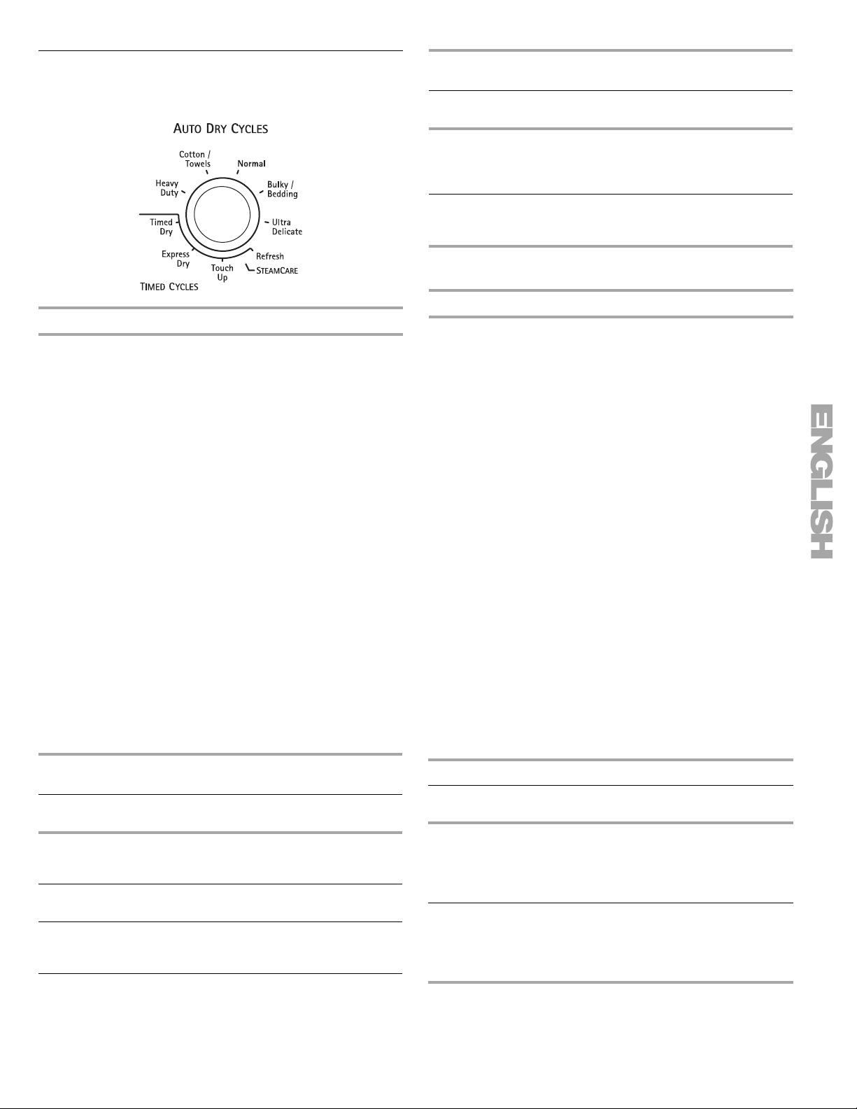
Cycles
Select the drying cycle that matches the type of load you are drying. See Auto or Timed Preset Cycle Settings charts.
Auto Preset Cycle Settings
Follow care label directions.
Auto Dry Cycles
Load Type
BULKY/BEDDING
Jackets, comforters,
cotton or pol
filled pillows
yester fiber
Temperature Time*
(Minutes)
Medium 60
Auto Dry Cycles
Auto Dry Cycles allow you to match the cycle to the load you are
drying. See the following Auto Preset Cycle Settings chart. Each
cycle dries certain fabrics at the recommended temperature. A
sensor detects the moisture in the load and automatically adjusts
the drying time for optimal drying.
Heavy Duty
Use this cycle to get high heat for heavyweight mixed loads, cottons, and jeans.
Cotton/Towels
Use this cycle to get high heat for drying heavy fabrics such as towels, sheets, or cottons.
Normal
Use this cycle to get medium heat for drying casual business clothes, permanent press blends, or work clothes.
Bulky/Bedding
Use this cycle to get medium heat for drying large items that
require very long drying times such as jackets, comforters, and
cotton or polyester fiber filled pillows. Rearrange the load when
the Damp Dry signal sounds. This step will aid in the drying
process.
Ultra Delicate
Use this cycle to get extra-low heat to gently dry items such as washable knit fabrics, blouses, or lingerie.
Auto Preset Cycle Settings
Follow care label directions.
Auto Dry Cycles
Load Type
HEAVY DUTY
Heavyweight mixed loads,
cottons, jeans
COTTON/TOWELS
Towels, sheets, cottons
NORMAL
Casual clothes,
permanent pr
ess
Temperature Time*
(Minutes)
High 50
High 45
Medium 40
ULTRA DELICATE
Washable knits, blouses,
ngerie
li
*Estimated Time with Auto Dry Level (Normal) setti
vary depending on load type and load size.
Extra-Low 25
ng. Time will
SteamCare Cycles
Use SteamCare Cycles to help smooth out wrinkles from dry
items, such as clothes that have been worn or clothes that have
been left in the dryer too long. When a SteamCare Cycle is
selected, the estimated time remaining display shows the actual
time remaining in the cycle.
NOTE: Results m
garments with wrinkle-free finish may yield better results than
those without.
Use of a fabric softener sheet is not recommended with
ste
am cycles as it may cause temporary staining on the
clothes.
ay vary depending on fabric. 100% cotton
Refresh
This cycle is best for smoothing out wrinkles and reducing odors
from loads consisting of one to four dry items of wrinkle-free
cotton, cotton-polyester blend, common knits, and synthetic
garments. In this cycle a small amount of water is sprayed into
the dryer drum after several minutes of tumbling with heat. The
dryer will continue to tumble with heat followed by a brief cool
down. The heat level and cycle time are not adjustable.
Touch Up
This cycle is best for touching up clothes that have been left in
the dryer too long. In this cycle, a small amount of water is
sprayed into the dryer drum after several minutes of tumbling
with heat. The dryer will continue to tumble with heat followed by
a brief cool down. The dry time and temperature can be adjusted
for this cycle.
NOTE: Overloading the dryer may not yield the same results.
SteamCare Preset Cycle Settings
Timed Cycles
Load Type
REFRESH
Helps to smooth out
kles and reduce odors
wrin
from loads consisting of
one to four dry items.
Touch Up Helps to smooth out wrinkles in loads left in the dryer for an extended period.
Default
Temperature
Medium High
Medium High 20
Default Time
(Minutes)
15
15
 Loading...