

Kenmore 11094762300 Installation Guide

27 IN. (69 CM) GAS LAUNDRY CENTER
INSTALLATION INSTRUCTIONS
INSTRUCCIONES DE INSTALACION PARA EL CENTRO
DE LAVANDERIA A GAS DE 27 PULG. (69 CM)
Table ofContents / |ndice
WASHER/DRYER SAFETY ............................. 1
INSTALLATION INSTRUCTIONS ................... 3
Tools and Parts ............................................. 3
Alternate Parts ............................................... 3
Location Requirements ................................ 3
Drain System ................................................. 5
Electrical Requirements ................................ 5
Gas Supply Requirements ............................ 6
Venting Requirements ................................... 7
Remove Shipping Strap ................................ 7
Install Leveling Legs ...................................... 8
Connect the Drain Hose ................................ 8
Connect the Inlet Hoses ................................ 8
Secure the Drain Hose .................................. 9
Plan Vent System .......................................... 9
Install Vent System ...................................... 11
Level Laundry Center .................................. 11
Make Gas Connection ................................ 12
Connect Vent ............................................... 12
Complete Installation .................................. 12
SERVICE NUMBERS ................. BACK COVER
SEGURIDAD DE LA LAVADORA/SECADORA.***., 14
INSTRUCCIONES DE INSTALAClON .................... 15
Herramientas y piezas ........................................... 15
Piezas alternativas ................................................. 16
Requisites de Iocalizaci6n .................................... 16
Sistema de desagL_e ........................................... 17
Requisitos el_ctricos ............................................. 18
Requisitos del suministro de gas .......................... 19
Requisitos de ventilaci6n ...................................... 20
Quite el fleje de embalaje ...................................... 21
Instalaci6n de tas patas niveladoras ..................... 21
Conecte ta manguera de desagQe ........................ 21
Conecte las mangueras de entrada ...................... 22
Fijaci6n de ta manguera de desagQe .................... 23
Planificaci6n del sistema de ventilaci6n ............... 23
Instalaci6n del sistema de ventilaci6n .................. 25
C6mo nivelar el centro de lavanderia ................... 25
Conexi6n del suministro de gas ........................... 25
Conexi&n del ducto de escape ............................. 26
C6mo terminar la instalaci6n ................................ 26
NUMEROS DE SERVICIO ......... CONTRAPORTADA
WASHER/DRYER SAFETY
Your safety and the safety of others are very important.
We have provided many important safety messages in this manual and on your appliance. Always read and obey all safety
messages.
This is the safety alert symbol.
This symbol alerts you to potential hazards that can kill or hurt you and others.
All safety messages will follow the safety alert symbol and either the word "DANGER" or "WARNING."
These words mean:
You can be killed or seriously injured if you don't immediately
follow instructions,
You can be killed or seriously injured if you don't follow
instructions,
All safety messages will tell you what the potential hazard is, tell you how to reduce the chance of injury, and tell you what can
happen if the instructions are not followed.
IMPORTANT SAFETY INSTRUCTIONS
When discarding or storing your old clothes dryer, remove the door.
SAVE THESE INSTRUCTIONS
3980417
WARNING: For your safety, the information in this manual must be followed to minimize
the risk of fire or explosion, or to prevent property damage, personal injury, or death.
- Do not store or use gasoline or other flammable vapors and liquids in the vicinity of this
or any other appliance.
- WHAT TO DO IF YOU SMELL GAS:
• Do not try to light any appliance.
• Do not touch any electrical switch; do not use any phone in your building.
• Clear the room, building, or area of all occupants.
• Immediately call your gas supplier from a neighbor's phone. Follow the gas supplier's
instructions.
• If you cannot reach your gas supplier, call the fire department.
- Installation and service must be performed by a qualified installer, service agency, or
the gas supplier.
In the State of Massachusetts, the following installation instructions apply:
• Installations and repairs must be performed by a qualified or licensed contractor, plumber, or gasfitter qualified or
licensed by the State of Massachusetts.
• If using a ball valve, it shall be a T-handle type.
• A flexible gas connector, when used, must not exceed 3 feet.
2

INSTALLATION INSTRUCTIONS
Check that you have everything necessary for correct installation.
Proper installation is your responsibility.
Tools needed:
• 8in. or lOin. adjustable • Knife
wrench (for gas
connections) • Safety glasses
• Flat-blade screwdriver • Vent clamps
• Adjustable wrench that • Pipe-joint compound
opens to 1 in. (2.5 cm) or resistant to L.R gas
9/16in. (14 ram) open-end • Caulking gun and
wrench (for adjusting compound (for installing
laundry center feet) new exhaust vent)
• Level • Gloves
• % in. nut driver or socket • Pliers that open to
wrench 1%e in. (3.95 cm)
• Wood block(for leveling) • Scissors
• Ruler or measuring tape • Tin snips(new vent
installation)
Parts supplied:
Remove parts package from the washer basket. Check that all
parts are included.
3
Parts listed are available from your local Sears store or Sears
Service Center. For further information, please call
1-800-4-MY-HOME ®(1-800-469-4663}.
If You Have You Will Need to Buy
Laundry tub or Sump pump system (if not already
standpipe taller than available)
96 in. (2.4 m)
1 in. (2.5 cm) 2 in. (5 cm) diameter to 1 in. (2.5 cm)
diameter standpipe diameter standpipe adapter, Part
Number 3363920
Overhead sewer Standard 20 gal. (76 L) 34 in. (86.4 cm)
tall drain tub or utility sink and sump
pump (available from local plumbing
suppliers)
Floor drain Siphon break, Part Number 285320,
additional drain hose, Part Number
285702 and connector kit,
Part Number 285442
Drain hose too short Drain hose, Part Number 285664 and
connector kit, Part Number 285442
Lint clogged drain Drain protector, Part Number 367031
Water faucets 2 longer water fill hoses:
beyond reach of fill 6 ft (1.8 m) Part Number 76314,
hoses 10 ft (3.0 m) Part Number 350008
1. Water inlet hoses (2)
2. Inlet hose flat washers (4)
3. Front leveling feet with nuts (2)
4. Shipping strap (not in parts
bag, see "Remove Shipping Strap")
Parts needed:
Check local codes and with gas supplier, check existing gas
supply, electrical supply and venting, and read "Electrical
Requirements," "Gas Supply Requirements" and "Venting
Requirements" before purchasing parts.
Mobile home installations require special parts (listed following)
available for purchase from your local Sears store or Sears
Service Center. For further information, please call
1-800-4-MY-HOME _(1-800-469-4663).
• Mobile Home Installation Kit. Ask for Part Number 346764.
• Metal exhaust system hardware.
5. Drain hose
6. Yellow, single wire
hose clamp
7 Silver, double-wire
hose clamp
tL,X_):S;t©_'1_:_,eq ,, ye _s_;eyl1:,s
Explosion Hazard
Keep flammable materials and vapors, such as
gasoline, away from dryer.
Failure to do so can result in death, explosion, or fire.
You will need
• A location that allows for proper exhaust installation. A gas
laundry center must be exhausted to the outdoors. See
"Venting Requirements."
• A grounded electrical outlet located within 2 ft (61 cm) of
either side of the laundry center. See "Electrical
Requirements."

• Asturdyfloortosupportthelaundrycenterweight(laundry
center,waterandload)of500Ibs(226.8kg).
• Alevelfloorwithamaximumslopeof1in.(2.5cm)under
entirelaundrycenter.Clothesmaynottumbleproperlyand
automaticsensorcyclesmaynotoperatecorrectlyiflaundry
centerisnotlevel.Installingoncarpetisnotrecommended.
• Awaterheatersettodeliver120°F(49°C)watertothe
washer.
• Hotandcoldwaterfaucetslocatedwithin4f_(1.2m)ofthe
hotandcoldwaterfillvalves,andwaterpressureof5-100psi
(34.5-689.6kPa).
Thelaundrycentermustnotbeinstalledorstoredinanarea
whereitwillbeexposedtowaterand/orweather.
Donotoperateyourwasherintemperaturesatorbelow32°F
(O°C).Somewatercanremaininthewasherandcancause
damageinlowtemperatures.See"LaundryCenterCare"inthe
"LaundryCenterUserInstructions"forwinterizinginformation.
Donotoperateyourdryerintemperaturesbelow45°F(7°C).At
lowertemperatures,thedryermightnotshutoffattheendofan
automaticcycle.Thiscanresultinlongerdryingtimes.
Checkcoderequirements.Somecodeslimit,ordonotpermit,
installationofthelaundrycenteringarages,closets,mobile
homes,orsleepingquarters.Contactyourlocalbuilding
inspector.
NOTE:Nootherfuel-burningappliancecanbeinstalledinthe
sameclosetasadryer.
Installation Clearances
The location must be large enough to fully open the dryer door.
Laundry Center Dimensions
Minimum installation spacing for recessed area or closet
installation
The following dimensions shown are for the minimum spacings
allowed.
• Additional spacing should be considered for ease of
installation and servicing.
• Additional clearances might be required for wall, door and
floor moldings.
• Additional spacing of 1 in. (2.5 cm) on all sides of the laundry
center is recommended to reduce noise transfer.
For closet installation, with a door, minimum ventilation
openings in the top and bottom of the door are required.
Louvered doors with equivalent ventilation openings are
acceptable.
• Rear clearance may be 0 in. when house exhaust system is
lined up directly with dryer exhaust.
o _ o
m
m
(o_) (msm) (ore) (2.sm)(m.sm)
f 2
"
1. Recessed area
2. Side view - closet or confined area
3. Closet door with vents
(14=.)
a'(T.eun)
3
* Most installations require a minimum 51/2in. (14 cm) clearance
behind the dryer for the exhaust vent with elbow. See "Venting
Requirements."
Mobile Home - Additional Installation Requirements
This laundry center is suitable for mobile home installations.
The installation must conform to the Manufactured Home
Construction and Safety Standard, Title 24 CFR, Part 3280
(formerly the Federal Standard for Mobile Home Construction
and Safety, Title 24, HUD Part 280).
Mobile home installations require:
• Metal exhaust system hardware which is available for
purchase from your local Sears store or Sears Service Center.
• Mobile Home Installation Kit Part Number 346764. See "Tools
and Parts" section for ordering information.
• Special provisions must be made in mobile homes to
introduce outside air into the dryer. The opening (such as a
nearby window) should be at least twice as large as the dryer
exhaust opening.
4

The laundry center can be installed using the standpipe drain
system (floor or wall), the laundry tub drain system, or the floor
drain system. Select the drain hose installation method you need.
See "Alternate Parts."
Standpipe drain system - wall or floor (view 1 & 2)
The standpipe drain requires a minimum diameter standpipe of
2 in. (5 cm). The minimum carry-away capacity can be no less
than 17 gal. (64 L) per minute. A 2 in. (5 cm) diameter to 1 in.
(2.5-cm) diameter standpipe adapter kit is available. See
"Alternate Parts."
The top of the standpipe must be at least 39 in. (99 cm) high and
no higher than 96 in. (2.4 m) from the bottom of the washer.
1 2
Laundry tub drain system (view 3)
The laundry tub needs a minimum 20 gal. (76 L) capacity. The top
of the laundry tub must be at least 34 in. (86.4 cm) above the floor
and no higher than 96 in. (2.4 m) from the bottom of the washer.
Floor drain system (view 4)
The floor drain system requires a siphon break that may be
purchased separately. See "Alternate Parts."
The siphon break must be a minimum of 28 in. (71 cm) from the
bottom of the washer. Additional hoses might be needed.
Electrical Shock Hazard
Plug into a grounded 3 prong outlet.
Do not remove ground prong.
Do not use an adapter.
Do not use an extension cord.
Failure to follow these instructions can result in death,
fire, or electrical shock.
A 120-volt, 60-Hz., AC-only, 15- or 20-ampere, fused
electrical supply is required. Time-delay fuse or circuit
breaker is recommended. It is also recommended that a
separate circuit serving only this appliance be provided.
To minimize possible shock hazard, the cord must be
plugged into a mating, 3 prong, ground-type outlet, grounded
in accordance with local codes and ordinances. If a mating
outlet is not available, it is the personal responsibility and
obligation of the customer to have the properly grounded
outlet installed by a qualified electrician.
IMPORTANT: The laundry center must be electrically
grounded in accordance with local codes, or in the absence
of local codes, with the National Electrical Code,
ANSI/NFPA 70.
If codes permit and a separate ground wire is used, it is
recommended that a qualified electrician determine that the
ground path is adequate.
Do not ground to a gas pipe.
Check with a qualified electrician if you are not sure the
laundry center is properly grounded.
Do not have a fuse in the neutral or ground circuit.
GROUNDING INSTRUCTIONS
• For a grounded, cord-connected washer/dryer:
This washer/dryer must be grounded. In the event of mal-
function or breakdown, grounding will reduce the risk of
electric shock by providing a path of least resistance for
4
electric current. This washer/dryer is equipped with a cord
having an equipment-grounding conductor and a grounding
plug. The plug must be plugged into an appropriate outlet
that is properly installed and grounded in accordance with
all local codes and ordinances.
WARNING: Improper connection of the equipment-
grounding conductor can result in a risk of electric shock.
Check with a qualified electrician or service representative or
personnel if you are in doubt as to whether the washer/dryer
is properly grounded. De not modify the plug provided with
the washer/dryer: if it will not fit the outlet, have a proper
outlet installed by a qualified electrician.
SAVE THESE INSTRUCTIONS

Must include a shutoff valve:
An individual shutoff valve must be installed within six (6) feet
(1.8 m) of the laundry center in accordance with the National
Fuel Gas Code, ANSI Z223.1/NFPA 54. The location should
be easy to reach for opening and closing.
1
2
ExplosionHazard
UseanewAGAorCSAapprovedgassupplyline.
Installashut-offvalve.
Securelytightenallgasconnections.
IfconnectedtoLP,haveaqualifiedpersonmakesure
gaspressuredoesnotexceed13"(33cm)water
column.
Examplesofaqualifiedpersoninclude:
licensedheatingpersonnel,
authorizedgascompanypersonnel, and
authorized service personnel.
Failure to do so can result in death, explosion, or fire.
Gas Type
Natural Gas:
This laundry center is equipped for use with NATURAL GAS. It is
design-certified by CSA International for L.R (propane or butane)
gases with appropriate conversion.
• Your laundry center must have the correct burner for the type
of gas in your home. Burner information is located on the
rating plate in the door well of your dryer. If this information
does not agree with the type of gas available, contact your
local Sears store or Sears Service Center.
LP. gas conversion:
Conversion must be made by a qualified technician.
No attempt shall be made to convert the appliance from the gas
specified on the model/serial rating plate for use with a different
gas without consulting the serving gas supplier.
IMPORTANT: The gas installation must conform with local codes,
or inthe absence of local codes, with the National Fuel Gas Code,
ANSI Z223.1/NFPA 54.
Gas Supply Line
• _/2in. IPS pipe is recommended
• 3/8in. approved tubing is acceptable for lengths under 20 ft
(6.1 m) if local codes and gas supplier permit.
• Lengths over 20 ft (6.1 m) should use larger tubing.
• Must include V8in. NPT plugged tapping accessible for test
gauge connection, immediately upstream of the gas supply
connection to the dryer (see illustration).
• Gas supply line coupling must be 34 in. (86.4 cm) to 37 in.
(94 cm) from the floor.
3
1, Gas shutoff valve
2. _ in. NPT plugged tapping
3. _/2in, NPT gas supply line
4. Gas supply line coupling 34 in. (86.4 cm) min.
to 37 in. (94 cm) max. from floor
If you are using natural gas, do not use copper tubing.
If your laundry center has been converted to use L.R gas,
% in. L.R compatible copper tubing can be used. If the total
length of the supply line is more than 20 ft (6.1 m), use larger
tubing.
NOTE: Pipe joint compounds that resist the action of L.R gas
must be used. Do not use TEFLON _<tape.
Dryer Gas Connection
• This laundry center is equipped with its own permanent,
flexible gas connector, design-certified by CSA International,
for connecting the laundry center to the gas supply line.
Flexible gas connector
Burner Input Requirements:
Elevations up to 10,000 feet (3,048 meters):
• The design of this laundry center is certified by CSA
International for use at altitudes up to 16,000 ft (3,048 m)
above sea level at the B.T.U. rating indicated on the model/
serial number plate. Burner input adjustments are not
required when the dryer is operated up to this elevation.
Elevations above 10,000 feet (3,048 meters):
• When installed above 10,000 ft (3,048 m) a 4% reduction of
the burner B.T.U. rating shown on the model/serial number
plate is required for each 1,000 ft (365 m) increase in
elevation.
Gas Supply Pressure Testing
• The laundry center must be disconnected from the gas
supply piping system during any pressure testing.
_TEFLON is a registered trademark of E.I. Du Pont De Nemours and Company
6
Fire Hazard
Use a heavy metal vent.
Do not use a plastic vent.
Do not use a metal foil vent.
Failure to follow these instructions can result in death
or fire.
WARNING: To reduce the risk of fire, this laundry center
MUST BE EXHAUSTED OUTDOORS.
4 in. (10.2 cm) heavy metal exhaust vent and clamps must be
used. DURASAFE TM venting products are recommended and are
available from your local Sears store or Sears Service Center.
DURASAFF M vent products can be purchased from your dealer.
For further information, please call 1-800-4-MY-HOME ®
(1-800-469-4663) or visit our Internet site at www.sears.cem.
• The dryer exhaust must not be connected into any gas vent,
chimney, wall, ceiling, or a concealed space of a building.
• Do not use an exhaust hood with a magnetic latch.
• Do not install flexible metal vent in enclosed walls, ceilings or
floors.
Use clamps to seal all joints. Exhaust vent must not be
connected or secured with screws or other fastening devices
which extend into the interior of the duct. Do not use duct
tape.
IMPORTANT: Observe all governing codes and ordinances.
Improper venting can cause moisture and lint to collect
indoors, which may result in:
• Moisture damage to woodwork, furniture, paint, wail-
paper, carpets, etc.
• Housecleaning problems and health problems.
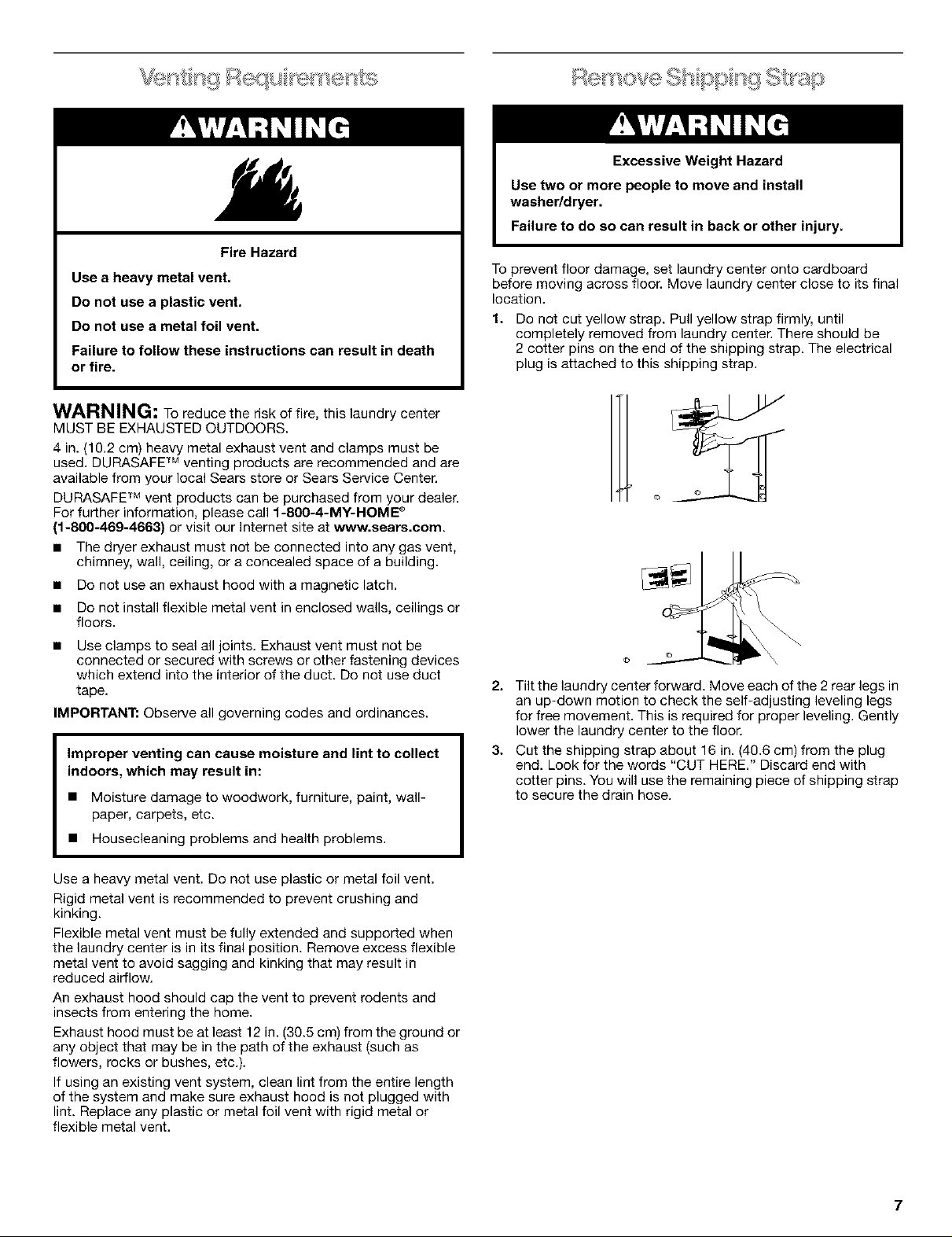
To prevent floor damage, set laundry center onto cardboard
before moving across floor. Move laundry center close to its final
location.
1.
Do not cut yellow strap. Pull yellow strap firmly, until
completely removed from laundry center. There should be
2 cotter pins on the end of the shipping strap. The electrical
plug is attached to this shipping strap.
2. Tilt the laundry center forward. Move each of the 2 rear legs in
an up-down motion to check the self-adjusting leveling legs
for free movement. This is required for proper leveling. Gently
lower the laundry center to the floor.
3. Cut the shipping strap about 16 in. (40.6 cm) from the plug
end. Look for the words "CUT HERE." Discard end with
cotter pins. You will use the remaining piece of shipping strap
to secure the drain hose.
Use a heavy metal vent. Do not use plastic or metal foil vent.
Rigid metal vent is recommended to prevent crushing and
kinking.
Flexible metal vent must be fully extended and supported when
the laundry center is in its final position. Remove excess flexible
metal vent to avoid sagging and kinking that may result in
reduced airflow.
An exhaust hood should cap the vent to prevent rodents and
insects from entering the home.
Exhaust hood must be at least 12 in. (30.5 cm) from the ground or
any object that may be in the path of the exhaust (such as
flowers, rocks or bushes, etc.).
If using an existing vent system, clean lint from the entire length
of the system and make sure exhaust hood is not plugged with
lint. Replace any plastic or metal foil vent with rigid metal or
flexible metal vent.
7

Install the front leveling feet
1. Prop up the front of the laundry center about 4 in. (10.2 cm)
with a wood block or similar object. The block needs to
support the weight of the laundry center.
2. Screw the lock nut onto each foot to within 1 in. (2.5 cm) of
the base.
4. Open clamp. Twist hose back and forth while pushing onto
drain connector on the side of the laundry center. Continue
until hose contacts the ribbed stops on the cabinet.
3. Screw the feet into the correct holes at the front corner of the
laundry center until the nuts touch the washer.
NOTE: Do not tighten the nuts until the laundry center is level.
4. Tilt the laundry center back and remove the wood block.
Gently lower the laundry center to the floor.
For mobile home use
Laundry centers with gas dryers must be securely fastened to the
floor.
Mobile home installations require a Mobile Home Installation Kit.
See "Tools and Parts" section for ordering information.
Proper connection of the drain hose protects your floors from
damage due to water leakage. To prevent the drain hose from
coming off or leaking, it must be installed per the following
instructions:
IMPORTANT: To ensure proper installation, this procedure must
be followed exactly.
1. Check the drain hose to see whether it is the proper length.
2. Wet the inside of the straight end of the drain hose with tap
water. DO NOT USE ANY OTHER LUBRICANT.
3. Squeeze ears of the silver, double-wire clamp with pliers to
open. Place clamp over the straight end of the drain hose
% in. (6.4 ram) from the end.
5. Place clamp over the area marked "CLAMR" Release clamp.
For laundry tub or standpipe drain systems
1. Open the yellow single-wire clamp and slide over the hooked
end of the drain hose to secure the rubber and corrugated
sections together.
2. Put hooked end of drain hose into laundry tub or standpipe.
Rotate hook to eliminate kinks.
1. Hooked end
2. Drain hose
To prevent drain water from going back into the washer:
• Do not straighten hooked end of the drain hose and force
excess drain hose into standpipe. Hose should be secure but
loose enough to provide a gap for air.
• Do not lay excess hose on the bottom of the laundry tub.
For use with floor drain
Remove the drain hose hook from the corrugated drain hose. You
may need additional parts. See "Floor Drain" under "Alternate
Parts."
Connect et oses
1.
Insert a new flat washer (supplied) into each end of the inlet
hoses. Firmly seat the washers in the couplings.
u
1 2
1.Coupling
mm)
2. Washer
Connect the inlet hoses to the water faucets
Make sure the washer basket is empty.
2. Attach the hose with the red coupling to the hot water faucet.
Screw on coupling by hand until seated on the washer.
8

3. Attach the hose with the blue coupling to the cold water NOTE: Replace inlet hoses after 5 years of use to reduce the risk
faucet. Screw on coupling by hand until seated on the of hose failure. Record hose installation or replacement dates for
washer, future reference.
4. Using pliers, tighten the couplings with an additional
two-thirds turn.
NOTE: Do not overtighten. Damage to the valves can result.
Clear the water lines
5. Run water through both faucets and inlet hoses, into a bucket
or laundry tub, to get rid of particles in the water lines that
might clog the inlet valve screens.
Connect the inlet hoses to the washer
6. Attach the hose with the blue coupling to the cold water (top)
inlet valve. Screw on coupling by hand until seated on the
washer. Using pliers, tighten the couplings with an additional
two-thirds turn.
NOTE: Do not overtighten. Damage to the valves can result.
u
• If you connect only one water hose, you must cap off the
remaining water inlet port.
• Periodically inspect and replace hoses if bulges, kinks, cuts,
wear, or leaks are found.
1. Move the laundry center to its final location and remove any
cardboard used to move the laundry center.
2. Locate the remaining piece of shipping strap. See "Remove
Shipping Strap."
Shipping Strap
3. Wrap the drain hose to the laundry tub leg or standpipe with
the shipping strap (1 or 2 below). Push fastener into the
nearest hole in the shipping strap. See illustration above.
1. Cold water inlet valve (blue)
2. Hot water inlet valve (red)
7. Attach the hose with the red coupling to the hot water
(bottom) inlet valve. Screw on coupling by hand until seated
on the washer. Using pliers, tighten the couplings with an
additional two-thirds turn.
NOTE: Do not overtighten. Damage to the valves can result.
If you are working in a closet or recessed area
Move the laundry center into its final position and remove
cardboard from under laundry center. Remove the access panel
by removing 3 Phillips-head screws and one bumper, located at
the top of the access panel. Set panel, screws, and bumper
aside. Complete hookup of water hoses and (on gas models) the
flexible gas connector through the access area. Replace access
panel upon completion of laundry center installation.
Check for leaks
8. Turn on the water faucets and check for leaks. A small
amount of water might enter the washer. You will drain this
later.
3
Ifthe water faucets and the drain standpipe are recessed, put
the hooked end of the drain hose in the standpipe. Tightly
wrap the shipping strap around the water inlet hoses and the
drain hose (3 above). Push fastener into the nearest hole in
the shipping strap. See illustration above.
Typical exhaust installations
Typical installations vent the dryer from rear of the laundry center.
Other installations are possible.
1 I-- 4
5
P
2
3 .... _8
1. Dryer 5. Elbow
2. Rigid metal or 6 Clamps
flexible metal vent 7. Elbow
3 Clamps 8. Exhaust hood
4. Waft
9
 Loading...