

Kenmore 11088752790 Owner’s Manual

Owner's Manual and
Installation Instructions
®
24-Inch Wide
LAUNDRY CENTER
Washer • Electric Dryer
IMPORTANT:
Read and follow all safety
and operating instructions
before first use of this product.
Sears, Roebuck and Co., Hoffman Estates, IL 60179 U.S.A.
PART NO. 3405593 PRINTED IN U.S.A.
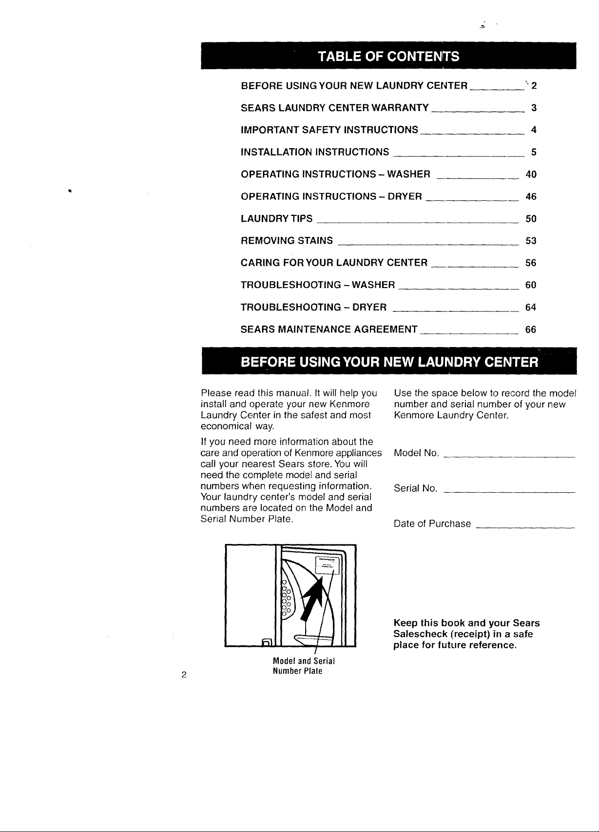
BEFORE USING YOUR NEW LAUNDRY CENTER
"2
SEARS LAUNDRY CENTER WARRANTY
IMPORTANT SAFETY INSTRUCTIONS
INSTALLATION INSTRUCTIONS
OPERATING INSTRUCTIONS - WASHER
OPERATING INSTRUCTIONS - DRYER
LAUNDRY TIPS
REMOVING STAINS
CARING FOR YOUR LAUNDRY CENTER
TROUBLESHOOTING - WASHER
TROUBLESHOOTING - DRYER
SEARS MAINTENANCE AGREEMENT
3
4
5
40
46
5O
53
56
60
64
66
Please read this manual. It will help you
install and operate your new Kenmore
Laundry Center in the safest and most
economical way.
If you need more information about the
care and operation of Kenmore appliances
call your nearest Sears store. You will
need the complete model and serial
numbers when requesting information.
Your laundry center's model and serial
numbers are located on the Model and
Serial Number Plate.
Model andSerial
2 Number Plale
Use the spaPe below to record the model
number and serial number of your new
Kenmore Laundry Center.
Model No.
Serial No.
Date of Purchase
Keep this book and your Sears
Salescheck (receipt) in a safe
place for future reference.

!
Full One Year Warranty on
Mechanical and Electrical Parts
For one year from the date of purchase,
if this laundry center is installed and
operated according to the instructions in
this manual, Sears will repair or replace
any of its mechanical or electrical parts
if they are defective in material or
workmanship.
NOTE: Exhausting your laundry center
with a plastic vent may void this warranty.
Pages 33-38 of this manual describe the
complete exhaust requirements for this
laundry center
Limited Five Year Warranty on
Gearcase Parts
After one year and until five years from
the date of purchase, Sears will replace
any gearcase parts that are defective in
material or workmanship. You must pay
the labor cost to have them installed.
Limited Ten Year Warranty on
Plastic Tub
After one year and until ten years from
the date of purchase, Sears will furnish
a replacement plastic tub for any plastic
tub that is defective in material or work-
manship. You n_ust pay the labor cost to
have the plastic: tub installed.
Warranty Re;;triction
If the laundry center is operated for any
purpose other tqan Private Family Use,
all warranty coverage is effective for only
90 days.
Warranty Service
Warranty service is available by contact-
ing your nearest Sears Service Center in
the United States.
This warranty applies only while this laundry
center is in use in the United States.
This warranty gives you specific legal
rights, and you may also have other rights
which vary from state to state,.
Sears, Roebuck and Co., Dept. 817WA,
Hoffman Estates, IL 60179.
Your safety and the safety of others is very important.
We have provided many important safety messages in this manual
and on your appliance. Always read and obey all safety messages.
This is the safety alert symbol. This symbol alerts
you to hazards that can kill or hurt you and others.
All safety messages will be preceded by the =_afety
alert symbol and the word "DANGER" or "WARNING:'
These words mean:
You will be killed or seriously
injured if you don't follow
instructions.
You can he killed or seriously
injured if you don't follow
instructic,ns.
All safety messages will identify the hazard, tell you how to reduce the
chance of injury, and tell you what can happen if the instructions are
not followed.

YOUR SAFETY IS IMPORTANTTO US
WARNING: To reduce the risk of fire,
electric shock, or injury to persons when
using your laundry center, follow basic
precautions, including the following:
• Read all instructions before using
the laundry center.
• Do not wash or dry articles that have
been previously cleaned in, washed in,
soaked in, or spotted with gasoline, dry-
cleaning solvents, or other flammable
or explosive substances as they give
off vapors that could ignite or explode.
• Do not add gasoline, dry-cleaning
solvents, or other flammable or explosive
substances to the wash water. These
substances give off vapors that could
ignite or explode.
• Under certain conditions, hydrogen
gas may be produced in a hot water
system that has not been used for more
than 2 weeks. HYDROGEN GAS IS
EXPLOSIVE. If the hot water system
has not been used for more than 2
weeks, turn on all hot water faucets
and let the water flow from each for
several minutes before using the
washing machine. This will release any
accumulated hydrogen gas. Because
the gas is flammable, do not smoke
or use an open flame during this time.
• Do not allow children to play on or in
the laundry center. Close supervision of
children is necessary when the laundry
center is used near children.
• Before the laundry center is removed
from service or discarded, remove the
washer lid and dryer door.
• Do not reach into the washer if the tub
or agitator is moving.
• Do not reach into the dryer if the drum
is moving.
• Do not install or store this laundry
center where it will be exposed to
the weatller.
• Do not t_.mper with controls.
• Do not repair or replace any part of the
laundry center or attempt any servicing
unless specifically recommended in the
Owner's Ivlanual or in published user-
repair instructions that you understand
and have; the skills to carry out.
• Do not use fabric softeners or products
to eliminste static unless recommended
by the manufacturer of the fabric softener
or product.
• Do not use heat to dry articles containing
foam rubber or similarly textured rubber-
like materials.
• Clean tint screen before or after each
load.
• Keep area around the exhaust opening
and adjacent surrounding areas free
from the accumulation of lint, dust, and
dirt.
• The interior of the machine and exhaust
vent should be cleaned periodically by
qualified service personnel.
SAVE THESE INSTRUCTIONS
IMPORTANT: Observe all governing codes and ordinances.

INSTALLATION OVERVIEW
For a complete list of tools and parts
needed, see pages 5-10.
A. SELECT LOCATION
FOR YOUR LAUNDRY CENTER (pgs. 11-16)
LaundryTub Drain System (p. 12) Standpipe Drain System (p. 13)
Floor Drain System (p. 13)
Recessed Area/'Closet Installation
Instructions (pgs. 14-15)
i
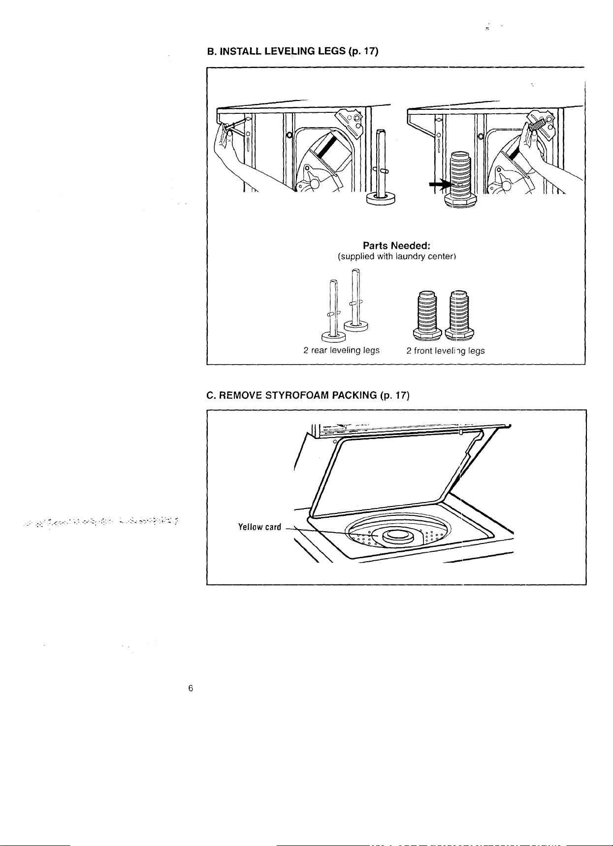
B. INSTALL LEVELING LEGS (p. 17)
Parts Needed:
(supplied with laundry center)
2 rear leveling legs
C. REMOVE STYROFOAM PACKING (p. 17)
Yellowcard
2 front leveliqg legs

D.MAKEELECTRICALCONNECTION(pgs.18-28)
Ifusingapowercord:
ToolsNeeded: PartsNeeded:
V4-inch nut #2 Phillips head
driver (shown) screwdriver
or socket wrench
Flashlight (optional
depending on installation)
If making a direct wire connection:
Tools Needed: Pa=rtsNeeded:
'/4-inch nut #2 Phillips head
driver (shown) screwdriver
or socket wrench
Flashlight (optional
_, Strain relief
New 3- or 4-wire, 30-amp.
U.L.-listed power supply
cord kit (includes strain relief)
10-gauge, 3- or 4-wire,
flexible armored
or non-metallic
sheathed copper cable
(with groundiqg wire)
3/4-inch,
U.L.-listed,
strain relief
Wire stripper depending on installation)

E. CONNECT DRAIN HOSE (pgs. 29-30)
Tools Needed:
Pliers that open f_l_-_
to 19/'6 inches
Flashlight (optional
depending on installation)
PUSH
Parts Needed:
(supplied with laundry center)
1 drain hose
1 silver, double-
1 yellow, single-wire wire hose clamp
hose clamp (top of (bottom of drain
drain hose) hose)
F. CONNECT INLET HOSES TO LAUNDRY CENTER (pgs. 30-31)
7
Tools Needed:
2 water inlet hoses
Parts Needed:
(supplied with laundry center)
Su
Pliers that open ..j---'_ \ \,_
to 19/%inches
Flashlight (optional
depending on installation)
4 flat water inlet hose washers

G. CONNECT INLET HOSES TO WATER FAUCETS (p. 31)
Tools Needed:
Pliers that open __
to1%6 inches _ OR_'
,uc e,
(optional
depending on
installation)
H. SECURE DRAIN HOSE (p. 32)
Flashlight (optional
depending on installation)
Parts Needed:
(supplied with laundry center)
2 water inlet hoses
(
Tools Needed:
Flashlight (optional
depending on installation)
Parts Needed:
(supplied with laundry center)
Plastic strap

I. LEVEL LAUNDRY CENTER (p. 33)
Tools Needed:
/16-inch
open-end wrench
Flashlight (optional
depending on installation) Wood block
J. CONNECT EXHAUST (pgs. 33-38)
Parts Needed:
(Supplied with laundry center)
2 front leveling legs with nuts
!_t-± i
10
Tools Needed:
Tin snips
Flashlight
(optional depending
on inslallation)
Y
Flat-bladed
screwdriver
I
Parts Needed:
4-inch rigid or flexible
heavy metal vent
4-inch outlet
exhaust haod
4-inch metal elbow(s)
(optional depending
on installation)
O0
O0
(4) 4-inch
diameter clamps

A. SELECT LOCATION FOR
YOUR LAUNDRY CENTER
Selecting the proper location
for your laundry center will improve
its performance, make installation
easier and minimize concerns like
washer walk or noise.
Check location where laundry center
will be installed. Proper installation is
your responsiMlity. Make sure you
have everything necessary for correct
installation (see pages 12-13).
This laundry center can be installed
using one of three systems:
• Laundry tub ,drain system (p. 12)
• Standpipe drain system (p. 13)
• Floor drain system (p. 13)
The laundry center must not be installed
where it can be exposed to water and/or
weather.
• Proper operation of washer cycles
requires temperatures above 32°F
(at lower temperatures, some water
may remain in washer). See page 59
for Winterizing Information.
Explosion Hazard
Keep flammable materials and vapors,
such as gasoline, away from dryer.
Failure to do so can result in death,
explosion, or tire.
• Proper operation of dryer cycles
requires temperatures above 45°F (at
lower temperatures, the dryer may not
shut off at the end of automatic cycles
and drying times will be extended).
• Check code requirements. Some
codes limit or do not permit installation
of laundry centers in garages, closets,
mobile homes or sleeping quarters.
Contact your local building inspector.
11

LAUNDRY TUB DRAIN SYSTEM
Grounded receptacle:
Within 31/2feet of either
side of laundry center.
Separate
30-amp.
fuse.
Hot and cold water faucets: Must
provide water pressure between 5-100
psi and be within 4 feet ol the hot and
cold water fill valves attached to the
back of the laundry center
Laundry tub drain
system: Needs a
minimum 20-gallon
laundry tub.
Support: Floor must be
sturdy enough to support a
total weight of 500 pounds
(includes laundry center and
load weight)
12
Level floor: Maximum
allowable slope under entire
laundry center- 1 inch.
Top of tub must be at least
39-inches above floor and
no higher than 96 inches
from bottom cf laundry center.

ALTERNATE LOCATIONS-
STANDPIPE AND FLOOR DRAIN SYSTEMS
Standpipe drain system: Needs a two-inch
minimum diameter standpipe with minimum
carry-away capacity of 17 gallons per minute.
Top of standpipe must be at least 39 inches
above floor and no higher than 96 inches
from bottom of laundry center.
Floor drain sys'tem: Requires a siphon
break, see chart below. A minimum carry-
away capacity o1'17 gallons per minute is
required.
If you have: You may need to buy:
Laundry tub or standpipe Sump pump system
taller than 96 inches (if not already available)
1-inch diameter standpipe 2-inch diameter to 1-inch diameter
standpipe adapter, Part No. :3363920
Overhead sewer Standard 20 gallon, 39-inch tall drain
tub or utility sink and sump pump
(available from local plumbing suppliers)
Floor drain Siphon break, Part No. 285320;
additional drain hose, Part No. 3357090;
and connector kit, Part No. 285442
Parts listed are available from your local Sears store or Sears Service Center.
Call 1-800-366-PART (1-800-366-7278).

RECESSED AREA/CLOSET
INSTALLATION INSTRUCTIONS
Check governing codes and ordinances.
This laundry center may be installed in
a recessed area or closet.
The laundry center must not be installed
LAUNDRY CENTER DIMENSIONS
Most installations will require at least
5-inch clearance behind the dryer for
the dryer vent.
Location must be large enough to fully
open dryer door.
where it can be exposed to water and/or
weather.
i
• Proper operation of washer cycles
requires temperatures above 32°F
(at lower temperatures, some water
may remain in washer). See page 59
for Winterizing Information.
• Proper operation of dryer cycles
requires temperatures above 45°F (at
lower temperatures, the dryer may not
shut off at the end of automatic cycles
and drying times will be extended).
• Check code requirements. Some
codes limit or do not permit installation
of laundry centers in garages, closets,
mobile homes or sleeping quarters.
Contact your local building inspector.
WARNING: To reduce the risk of fire, this
appliance must be exhausted outdoors.
NOTE: No fuel burning appliances
may be installed in the same closet
as your laundry center.
"_.--'_f_ 237/8"
14

MINIMUM INSTALLATION SPACING
• The installation spacing (shown below) is
in inches and is the minimum allowable.
• Additional spacing should be considered
for ease of installation and servicing.
• If closet door is installed, the minimum
air openings in top and bottom are
required. Louvered doors with equivalent
air openings in top and bottom are
acceptable.
• Recessed area and closet installations
require a 6-inch minimum clearance
above the laundry center.
• All installations must be exhausted
outside. Use at least the minimum
dimensions indicated.
_t_
6"
-T-
**48 ._;q.in._
minimum
ventilation
O oo oO
FRONTVIEW SIDEVIEW FRONTVIEW
(DOOR NOT SHOWN) (DOORSHOWN) (DOORWITH VENT)
* Additionalclearancesfor wall, doorandfloormoldingsmayberequired.
** Openingisminimumforclosetdoor.Louvereddoorwithequiva!entairopenings
isacceptable.
*** Additionalspaceis neededwhenexternalexhaustelbowis used. Canbe0"clearance
whenhouseexhaustingislinedupdirectlywithdryerexhaust.
ar_.=a
**24 ._;q.in.
_.._.' minirnum-
ventilation
ar_.'a
I<(_._**-51/2,"1"'--_I _-237/e"-_ I<_"1" --_f'lTlin._27'/4"_
4,
3"
7
__{
3"
7

MOBILE HOME REQUIREMENTS
The laundry center must not be installed
where it can be exposed to water and/or
weather.
• Proper operation of washer cycles
requires temperatures above 32°F
(at lower temperatures, some water
may remain in washer). See page 59
for Winterizing Information.
• Proper ,operation of dryer cycles
requires temperatures above 45°F (at
lower temperatures, the dryer may not
shut off at the end of automatic cycles
and drying times will be extended).
• Use at least the minimum installation
spacings described on page 15.
This laundry center is suitable for mobile
home installations. The installation must
conform to the Manufactured Home
Construction and Safety Standard, Title
24 CFR, Part 3280 (formerly the Federal
Standard for Mobile Homes Construction
and Safety, Title 24, HUD Part 280).
• Laundry center exhaust vent must
not be connected with screws or other
devices which extend into the interior
of the vent.
• Laundry center must be exhausted
outdoors. The exhaust vent must be
securely fastened to a noncombustible
portion of the mobile home structure
and must not terminate beneath the
mobile home.
I\
El00,///
0utside
wall
/
/Enclosure
16

B. INSTALL LEVELING LEGS
To install rear legs:
STEP 1. If you have not already done
so, lay the laundry center on its side.
Because of the weight of the laundry
center, two people should lay it down.
STEP 2. Push legs into holes in rear
corners until they snap into place.
STEP 3. Check adjustability of rear
legs, by pushing in one leg. The other
leg should come out. Check both legs.
If they do not adjust, repeat STEP 2.
To install front Ilegs:
STEP 1. Screw front legs into the holes
in the triangular braces in front corners.
Screw them in with an adjustable wrench
to the diamond marks on the ridges.
STEP 2. Carefully stand the laundry
center upright. Because of the weight
of the laundry center, two people
should lift it.
C. REMOVE STYROFOAM
PACKING
.::_J :" ?:,i _'-.<_,; _L_, ,.> _:_;.:..,_ :;i: ,:_ -_.:t_. 7:.
To prevent floor damage, set laundry
center onto carCboard before moving
across floor.
Move laundry center close to its final
location.
STEP 1. Open the washer lid. The latch
under the dryer will keep the lid open.
Read, then remove the yellow card on
the agitator.
Yellow card
STEP 2. Pull the styrofoam packing out
of the washer.
17
D. MAKE ELECTRICAL
CONNECTION
It is your responsibility:
• To contact a qualified electrical installer.
• To assure that the electrical installation
is adequate and in conformance with
the National Electrical Code, ANSI/
NFPA 70-latest edition and all local
codes and ordinances.
Copies of the code standards listed
above may be obtained from:
National Fire Protection Association
Batterymarch Park
Quincy, Massachusetts 02269
ELECTRICAL REQUIREMENTS
The proper electrical connection
ensures a :safe installation that
meets local code requirements.
A three-wire or four-wire, single
phase 120/240-volt, 60-Hz., AC-only,
electrical supply (or tihree-wire or
four-wire, 120/208-volt if specified on
serial/rating plate) is required on a
separate 30-ampere circuit, fused on
both sides of the line. A time-delay fuse
or circuit breaker is recommended.
This laundP.! center is manufactured with
the 3-wire, frame-grounding conductor
connected to the NEUTRAL (center) of
the wiring harness of the terminal block.
Do not have a fuse in the neutral or
grounding circuit. A fuse in the neutral
or grounding circuit could result in an
electrical shock.
Use a 4-conductor cord when the laundry
center is installed in a mobile home or
an area where local codes do not permit
grounding through the neutral.
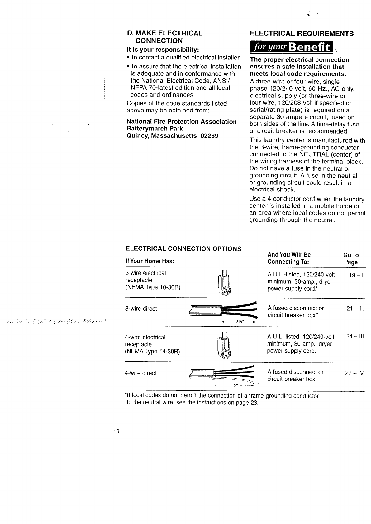
ELECTRICAL CONNECTION OPTIONS
And _bu Will Be GoTo
IfYour Home Has:
Connecting To: Page
A U.L.-listed, 120/240-volt
receptacle
3-wire electrical
(NEMA Type 10-30R)
3-wire direct 0
4-wire electrical
receptacle
(NEMA Type 14-30R)
4-wire direct
J
minimum, 30-amip., dryer
power supply cord.*
A fused disconnect or
circuil breaker box.*
A U.L.-listed, 120!240-volt
minimum, 30-amp., dryer
power supply cord.
A fused disconnect or
circuit breaker box.
*If local codes do not permit the connection of a frame-grounding conductor
to the neutral wire, see the instructions on page 23.
19-1.
21 - II.
24 - III.
27 - IV.
18
J
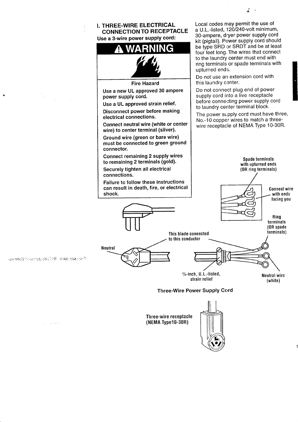
I. THREE-WIRE ELECTRICAL
CONNECTION TO RECEPTACLE
Use a 3-wire power supply cord:
Fire Hazard
Use a new UL approved 30 ampere
power supply cord.
Use a UL approved strain relief.
Disconnect power before making
electrical connections.
Connect neutral wire (white or center
wire) to center terminal (silver).
Ground wire (green or bare wire)
must be connected to green ground
connector.
Connect remaining 2 supply wires
to remaining 2 terminals (gold).
Securely tighten all electrical
connections.
Failure to follow these instructions
can result in death, fire, or electrical
shock.
Local codes may permit the use of
a U.L.-listed, 120/240-volt minimum,
30-ampere, dryer power supply cord
kit (pigtail). Power supply cord should
be type SRD or SRDT and be at least
four feet long. The wires that connect
to the laundry center must end with
ring terminals or spade terminals with
upturned ends.
Do not use an extension cord with
this laundry center.
Do not connect plug end of power
supply cord into a live receptacle
before connecting power supply cord
to laundry center terminal block.
The power sLpply cord must have three,
No.-10 copper wires to match a three-
wire receptacle of NEMA Type 10-30R.
Spadeterminals
withupturnedends
(ORringterminals)
/
This blade connected
Ne _ t0 thisconductor -__
_h-inch,U.L.-listed, Neutralwire
strainrelief (white)
Three-Wire Power Supply Cord
Three-wire receptacle
(NEMATypel0-30R)
I
terminals
(ORspade
terminals)

GROUNDING INSTRUCTIONS
This appliance must be grounded.
In the event of malfunction or break-
down, grounding will reduce the risk
of electric shock by providing a path
of least resistance for electric current.
The power supply cord must be plugged
into an appropriate outlet that is properly
installed and grounded in accordance
with all local codes and ordinances.
WARNING: Improper connection of the
equipment-grounding conductor can
result in a risk of electric shock. Check
with a qualified electrician or serviceman
if your are in doubt as to whether the
appliance is properly grounded.
Do not modify the plug on the power
supply cord. If it will not fit the outlet,
have a proper outlet installed by a
qualified electrician.
STEP 1. r)isconnect power.
STEP 2. Remove hold-down screw
and terminal block cover.
STEP 3. Attach a 3/4-inch, U.L.-listed,
strain relief to the hole below terminal
block opening. Strain relief should have
a tight fit with laundry center cabinet and
be in a horizontal position. Put the power
supply core through the strain relief.
STEP 4. Loosen or remove terminal block
screws. Co:_nect the neutral wire (white
or center) of power supply cord under
the center .:;crew of the terminal block.
STEP 5. Connect the other two wires
to outer terminal block screws. Securely
tighten all electrical connections.
Centersilver-colored
terminal blockscrew
Neutral
wire Neutral
(white) groundingwire
: (green/yell0w)
Terminalblockcover Hold-downscrew
3h..inch, U.L.-listed, connector
External ground
strain relief
3-Wire Connection with
Frame-Grounding Conductor
STEP 6. Tighten the strain relief screws.
STEP 7. Insert tab of terminal block
cover into slot of the laundry center rear
panel. Secu re cover with hold-down
screw.
If local codes do not permit the
connection of a frame-grounding
conductor to the neutral wire, see
the instructions on page 23.
Otherwise, proceed with Installation
on page 29.
2O

I1. THREE-WIRE ELECTRICAL
CONNECTION (DIRECT WIRE)
Prepare cable as directed:
Fire Hazard
Use 10 gauge solid copper wire.
Use UL approved strain relief.
Disconnect power before making
electrical connections.
Connect neutral wire (white or center
wire) to center terminal (silver).
Ground wire (green or bare wire)
must be connected to green ground
connector.
Connect remaining 2 supply wires
to remaining 2 terminals (gold).
Securely tighten all electrical
connections.
Failure to follow these instructions
can result in death, fire, or electrical
shock.
GROUNDING INSTRUCTIONS
This appliance must be connected to
a grounded metal, permanent 'wiring
system; or an equipment-grounding
conductor must be run with the circuit
conductors and ('onnected to the
equipment-grounding terminal or
lead on the appliance.
STEP 1. Disconnect power.
STEP la. Strip 31/2inches of outer
covering from er_dof cable. If using
3-wire cable with grounding wire, cut
the bare wire ew.m with outer covering.
J
STEP lb. Cut 1 inch of insulation from
the end of each insulated wire Shape
the end of each wire into a "U" shaped
hook.
\
The laundry center can be connected
directly to fused disconnect or circuit
breaker box with three-wire, flexible
armored or nonmetallic sheathed copper
cable (with grounding wire). All current-
carrying wires must be insulated.
A conduit connector must be installed at
junction box. Allow four feet of slack in the
line so laundry center can be moved if
servicing is ever necessary.
21
 Loading...