

Kenmore 11084762300, 11094962300 Installation Guide
27 IN. (69 CM) ELECTRIC LAUNDRY CENTER
INSTALLATION INSTRUCTIONS
INSTRUCCIONES DE INSTALACION PARA EL CENTRO
DE LAVANDERLA ELI'-'CTRICODE 27 PULG. (69 CM)
Table of Contents / |ndice
WASHER/DRYER SAFETY .............................. 1
INSTALLATION INSTRUCTIONS .................... 2
Tools and Parts ............................................. 2
Alternate Parts ............................................... 2
Location Requirements ................................ 2
Drain System ................................................. 3
Electrical Requirements ................................ 4
Electrical Connection .................................... 5
Venting Requirements ................................... 9
Remove Shipping Strap ................................ 9
Install Leveling Legs .................................... 10
Connect the Drain Hose .............................. 10
Connect the Inlet Hoses .............................. 10
Secure the Drain Hose ................................ 11
Plan Vent System ........................................ 12
Install Vent System ...................................... 13
Level Laundry Center .................................. 14
Connect Vent ............................................... 14
Complete Installation .................................. 14
SERVICE NUMBERS ................. BACK COVER
SEGURIDAD DE LA LAVADORA/SECADORA, 16
INSTRUCCIONES DE INSTALACION ................ 16
Herramientas y piezas ............................ 16
Piezas alternativas ............................................ 17
Requisitos de Iocalizaci6n ............................... 17
Sistema de desagL_e ....................................... 18
Requisitos el_ctricos ........................................ lg
Conexi6n el_ctrica ............................................ 20
Requisitos de ventilaci6n .................................. 24
Quite el fleje de embalaje ................................. 25
Instalaci6n de las patas niveladoras ................ 26
Conecte ta manguera de desagiJe ................... 26
Conecte ias mangueras de entrada ................. 27
Fijaci6n de la manguera de desagL_e............... 27
Planificaci6n del sistema de ventilaci6n .......... 28
Instalaci6n del sistema de ventilaci6n .............. 29
C6mo nivelar el centro de tavandeda ............... 30
Conexi6n del ducto de escape ........................ 30
C6mo terminar la instalaci6n ............................ 30
NOMEROS DE SERVICIO......CONTRAPORTADA
WASHER/DRYER SAFETY
Your safety and the safety of others are very important.
We have provided many important safety messages in this manual and on your appliance. Always read and obey all safety
messages.
This is the safety alert symbol.
This symbol alerts you to potential hazards that can kill or hurt you and others.
All safety messages will follow the safety alert symbol and either the word "DANGER" or "WARNING."
These words mean:
You can be killed or seriously injured if you don't immediatelE
follow instructions,
You can be killed or seriously injured if you don't follow
instructions,
All safety messages will tell you what the potential hazard is, tell you how to reduce the chance of injury, and tell you what can
happen if the instructions are not followed.
3980416
INSTALLATION INSTRUCTIONS
Check that you have everything necessary for correct installation.
Proper installation is your responsibility.
Tools needed:
• #2 Phillips and flat-blade • Knife
screwdriver
• Adjustable wrench that • Vent clamps
opens to 1 in. (2.5 cm) or
%6 in. open-end wrench • Caulking gun and
(for adjusting laundry compound (for installing
center feet) new exhaust vent)
• Level • Gloves
• % in. nut driver or socket • Pliers
wrench
• Wood block (for leveling) • Tin snips (for new vent
• Ruler or measuring tape installations)
• Wire stripper (direct wire
installations)
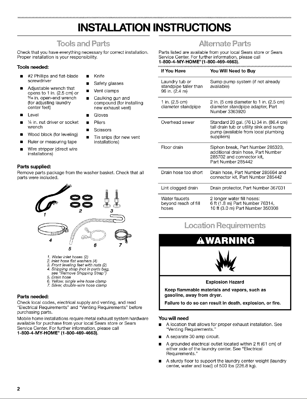
Parts supplied:
Remove parts package from the washer basket. Check that all
parts were included.
• Safety glasses
• Scissors
3
Parts listed are available from your local Sears store or Sears
Service Center. For further information, please call
1-800-4-MY-HOME ®(1-800-469-4663}.
If You Have You Will Need to Buy
Laundry tub or Sump pump system (if not already
standpipe taller than available)
96 in. (2.4 m)
1 in. (2.5 cm) 2 in. (5 cm) diameter to 1 in. (2.5 cm)
diameter standpipe diameter standpipe adapter, Part
Number 3363920
Overhead sewer Standard 20 gal. (76 L) 34 in. (86.4 cm)
tall drain tub or utility sink and sump
pump (available from local plumbing
suppliers)
Floor drain Siphon break, Part Number 285320,
additional drain hose, Part Number
285702 and connector kit,
Part Number 285442
Drain hose too short Drain hose, Part Number 285664 and
connector kit, Part Number 285442
Lint clogged drain Drain protector, Part Number 367031
Water faucets 2 longer water fill hoses:
beyond reach of fill 6 ft (1.8 m) Part Number 76314,
hoses 10 ft (3.0 m) Part Number 350008
4
5
1. Water inlet hoses (2)
2. Inlet hose flat washers (4)
3. Front leveling feet with nuts (2)
4. Shipping strap (not in parts bag,
see "Remove Shipping Strap")
5. Drain hose
6. Yellow, single wire hose clamp
7. Silver, double-wire hose clamp
Parts needed:
Check local codes, electrical supply and venting, and read
"Electrical Requirements" and "Venting Requirements" before
purchasing parts.
Mobile home installations require metal exhaust system hardware
available for purchase from your local Sears store or Sears
Service Center. For further information, please call
1-800-4-MY-HOME ®(1-800-469-4663).
6
tL,X_):S;t©_'t _:_,eq ,, ye _s_;eyl1:,s
Explosion Hazard
Keep flammable materials and vapors, such as
gasoline, away from dryer.
Failure to do so can result in death, explosion, or fire.
You will need
• A location that allows for proper exhaust installation. See
"Venting Requirements."
• A separate 30 amp circuit.
• A grounded electrical outlet located within 2 ft (61 cm) of
either side of the laundry center. See "Electrical
Requirements."
• A sturdy floor to support the laundry center weight (laundry
center, water and load) of 500 Ibs (226.8 kg).
2
• A level floor with a maximum slope of 1 in. (2.5 cm) under
entire laundry center. Clothes may not tumble properly and
automatic sensor cycles may not operate correctly if laundry
center is not level. Installing on carpet is not recommended.
• A water heater set to deliver 120°F (49°C) water to the
washer.
• Hot and cold water faucets located within 4 f_ (1.2 m) of the
hot and cold water fill valves, and water pressure of 5-100 psi
(34.5-689.6 kPa).
The laundry center must not be installed or stored in an area
where it will be exposed to water and/or weather.
Do not operate your washer in temperatures at or below 32°F
(O°C). Some water can remain in the washer and can cause
damage in low temperatures. See "Laundry Center Care" in the
Laundry Center User Instructions for winterizing information.
Do not operate your dryer at temperatures below 45°F (7°C). At
lower temperatures, the dryer might not shut off at the end of an
automatic cycle. This can result in longer drying times.
Check code requirements. Some codes limit, or do not permit,
installation of the laundry center in garages, closets, mobile
homes, or sleeping quarters. Contact your local building
inspector.
Installation Clearances
The location must be large enough to allow the dryer door to
open fully.
Laundry Center Dimensions
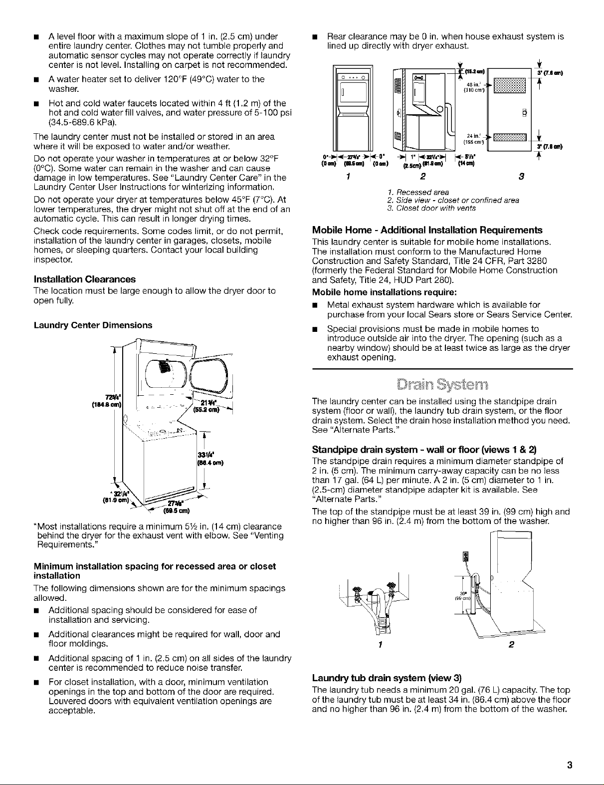
• Rear clearance may be 0 in. when house exhaust system is
lined up directly with dryer exhaust.
m
m
m
(o=111)(eUm) (ore)
1
(341_icnml)t
_11' pt=_,,_t It. =1,'
_.sm)_.=m) (14m)
2 3
1. Recessed area
2. Side view - closet or confined area
3. Closet door with vents
3' (7.6 cm)
3'(7.era)
Mobile Home - Additional installation Requirements
This laundry center is suitable for mobile home installations.
The installation must conform to the Manufactured Home
Construction and Safety Standard, Title 24 CFR, Part 3280
(formerly the Federal Standard for Mobile Home Construction
and Safety, Title 24, HUD Part 280).
Mobile home installations require:
• Metal exhaust system hardware which is available for
purchase from your local Sears store or Sears Service Center.
• Special provisions must be made in mobile homes to
introduce outside air into the dryer. The opening (such as a
nearby window) should be at least twice as large as the dryer
exhaust opening.
*Most installations require a minimum 5t/2 in. (14 cm) clearance
behind the dryer for the exhaust vent with elbow. See "Venting
Requirements."
Minimum installation spacing for recessed area or closet
installation
The following dimensions shown are for the minimum spacings
allowed.
• Additional spacing should be considered for ease of
installation and servicing.
• Additional clearances might be required for wall, door and
floor moldings.
• Additional spacing of 1 in. (2.5 cm) on all sides of the laundry
center is recommended to reduce noise transfer.
For closet installation, with a door, minimum ventilation
openings in the top and bottom of the door are required.
Louvered doors with equivalent ventilation openings are
acceptable.
The laundry center can be installed using the standpipe drain
system (floor or wall), the laundry tub drain system, or the floor
drain system. Select the drain hose installation method you need.
See "Alternate Parts."
Standpipe drain system - wall or floor (views 1 & 2)
The standpipe drain requires a minimum diameter standpipe of
2 in. (5 cm). The minimum carry-away capacity can be no less
than 17 gal. (64 L) per minute. A 2 in. (5 cm) diameter to 1 in.
(2.5-cm) diameter standpipe adapter kit is available. See
"Alternate Parts."
The top of the standpipe must be at least 39 in. (99 cm) high and
no higher than 96 in. (2.4 m) from the bottom of the washer.
1 2
Laundry tub drain system (view 3)
The laundry tub needs a minimum 20 gal. (76 L) capacity. The top
of the laundry tub must be at least 34 in. (86,4 cm) above the floor
and no higher than 96 in. (2,4 m) from the bottom of the washer.
Floor drain system (view 4)
The floor drain system requires a siphon break that may be
purchased separately. See "Alternate Parts."
The siphon break must be a minimum of 28 in. (71 cm) from the
bottom of the washer. Additional hoses might be needed.
It isyour responsibility
• Tocontact a qualified electrical installer.
• To be sure that the electrical connection is adequate and in
conformance with the National Electrical Code, ANSl/NFPA
70-latest edition and all local codes and ordinances.
A copy of the above code standards can be obtained from:
National Fire Protection Association, One Batterymarch Park,
Quincy, MA 02269.
• To supply the required 3 or 4 wire, single phase, 120/240-volt,
60-Hz., AC-only electrical supply (or 3 or 4 wire, 120/208-volt
electrical supply, if specified on the serial/rating plate) on a
separate 30-ampere circuit, fused on both sides of the line. A
time-delay fuse or circuit breaker is recommended. Connect
to an individual branch circuit. Do not have a fuse in the
neutral or grounding circuit.
• Do not use an extension cord.
• If codes permit and a separate ground wire is used, it is
recommended that a qualified electrician determine that the
ground path is adequate.
Electrical Connection
To properly install your laundry center, you must determine the
type of electrical connection you will be using and follow the
instructions provided for it here.
• If local codes do not permit the connection of a cabinet
ground connector to the neutral wire, see "Optional 3-wire
Connection."
• This laundry center is manufactured with a 3-wire, cabinet-
ground conductor connected to the NEUTRAL (white or
center wire) of the wiring harness at the terminal block.
• Use a 4-wire conductor cord when the laundry center is
installed in a mobile home or an area where local codes do
not permit grounding through the neutral.
If using a power supply cord:
• Use a UL listed power supply cord kit marked for use with
clothes dryers. The kit should contain:
• A UL listed 30 amp power supply cord, rated 120/240 volt
minimum. The cord should be type SRD or SRDT and be at
least 4 ft (1.22 m) long. The wires that connect to the dryer
must end in ring terminals or spade terminals with upturned
ends.
• A UL listed strain relief.
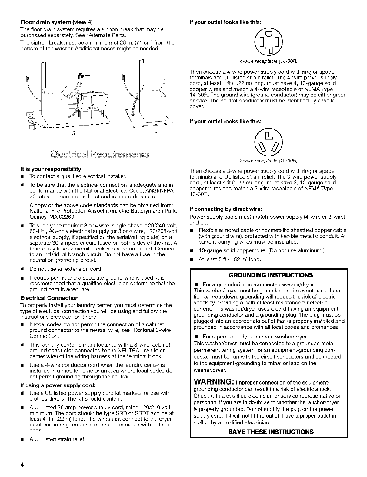
If your outlet looks like this:
©
4-wire receptacle (14-30Ft)
Then choose a 4-wire power supply cord with ring or spade
terminals and UL listed strain relief. The 4-wire power supply
cord, at least 4 ft (1.22 m) long, must have 4, 10-gauge solid
copper wires and match a 4-wire receptacle of NEMA Type
14-30R. The ground wire (ground conductor) may be either green
or bare. The neutral conductor must be identified by a white
cover.
If your outlet looks like this:
©
3-wire receptacle (10-30Ft)
Then choose a 3-wire power supply cord with ring or spade
terminals and UL listed strain relief. The 3-wire power supply
cord, at least 4 ft (1.22 m) long, must have 3, 10-gauge solid
copper wires and match a 3-wire receptacle of NEMA Type
10-30R.
If connecting by direct wire:
Power supply cable must match power supply (4-wire or 3-wire)
and be:
• Flexible armored cable or nonmetallic sheathed copper cable
(with ground wire), protected with flexible metallic conduit. All
current-carrying wires must be insulated.
• 10-gauge solid copper wire. (Do not use aluminum.)
• At least 5 ft (1.52 m) long.
GROUNDING INSTRUCTIONS
• For a grounded, cord-connected washer/dryer:
This washer/dryer must be grounded. In the event of malfunc-
tion or breakdown, grounding will reduce the risk of electric
shock by providing a path of least resistance for electric
current. This washer/dryer uses a cord having an equipment-
grounding conductor and a grounding plug. The plug must be
plugged into an appropriate outlet that is properly installed and
grounded in accordance with all local codes and ordinances.
• For a permanently connected washer/dryer:
This washer/dryer must be connected to a grounded metal,
_ermanent wiring system, or an equipment-grounding con-
ductor must be run with the circuit conductors and connected
to the equipment-grounding terminal or lead on the
washer/dryer.
WARNING: Improper connection of the equipment-
grounding conductor can result in a risk of electric shock.
3heck with a qualified electrician or service representative or
_ersonnel if you are in doubt as to whether the washer/dryer
properly grounded. Do not modify the plug on the power
supply cord: if it will net fit the outlet, have a proper outlet in-
stalled by a qualified electrician.
SAVE THESE INSTRUCTIONS
4
Power Supply Cord Direct Wire
Fire Hazard
Use a new UL listed 30 amp power supply cord.
Use a UL listed strain relief.
Disconnect power before making electrical connections.
Connect neutral wire (white or center wire) to center
terminal (silver).
Ground wire (green or bare wire) must be connected to
green ground connector.
Connect remaining 2 supply wires to remaining
2 terminals (gold).
Securely tighten all electrical connections.
Failure to do so can result in death, fire, or
electrical shock.
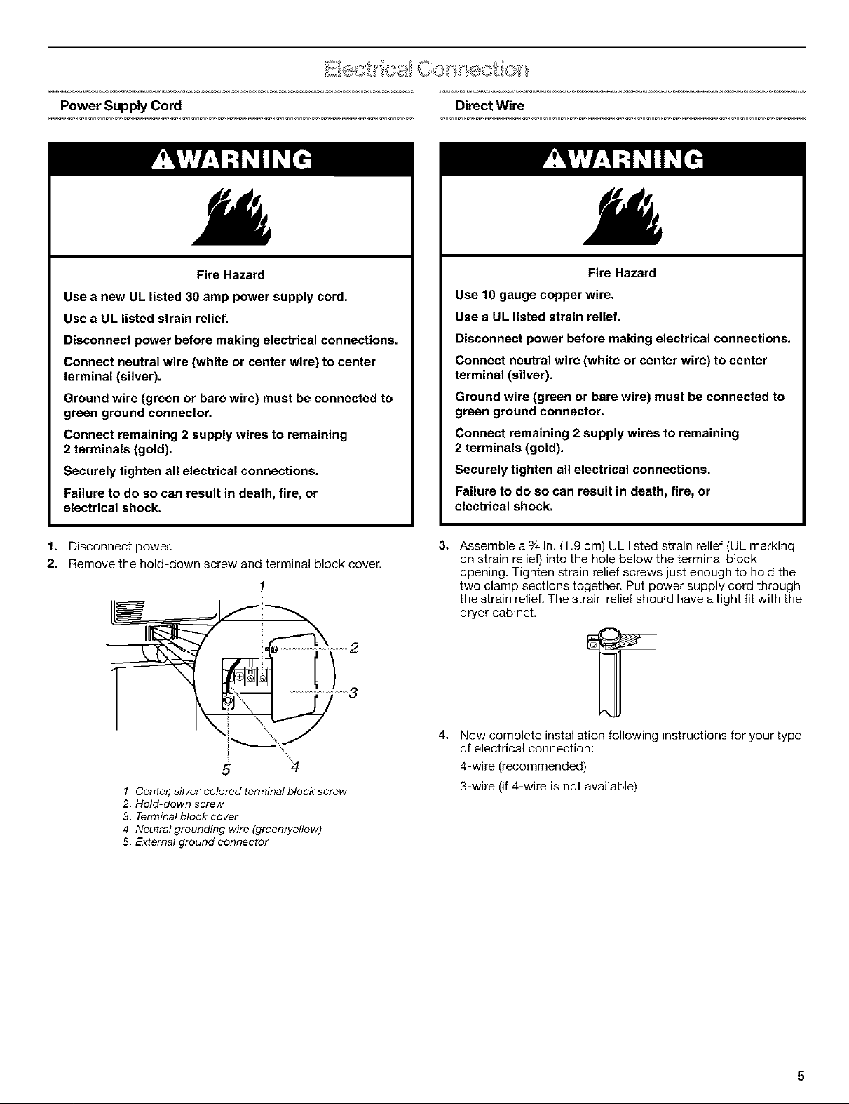
1. Disconnect power.
2. Remove the hold-down screw and terminal block cover.
2
Fire Hazard
Use 10 gauge copper wire.
Use a UL listed strain relief.
Disconnect power before making electrical connections.
Connect neutral wire (white or center wire) to center
terminal (silver).
Ground wire (green or bare wire) must be connected to
green ground connector.
Connect remaining 2 supply wires to remaining
2 terminals (gold).
Securely tighten all electrical connections.
Failure to do so can result in death, fire, or
electrical shock.
3.
Assemble a 3/4in. (1,9 cm) UL listed strain relief (UL marking
on strain relief) into the hole below the terminal block
opening. Tighten strain relief screws just enough to hold the
two clamp sections together. Put power supply cord through
the strain relief. The strain relief should have a tight fit with the
dryer cabinet,
5
1. Center, silver-colored terminal block screw
2. Hold-down screw
3. Terminal block cover
4. Neutral grounding wire (green/yellow)
5. External ground connector
4.
Now complete installation following instructions for your type
of electrical connection:
4-wire (recommended)
3-wire (if 4-wire is not available)
Electrical Connection Options
If your home has: And you will be Go to Section
connecting to:
4-wire receptacle A UL listed, 4-wire connection:
(NEMA Type 14-30R) 120/240 volt Power supply cord
amp., dryer
power supply
minimum, 30
cord*
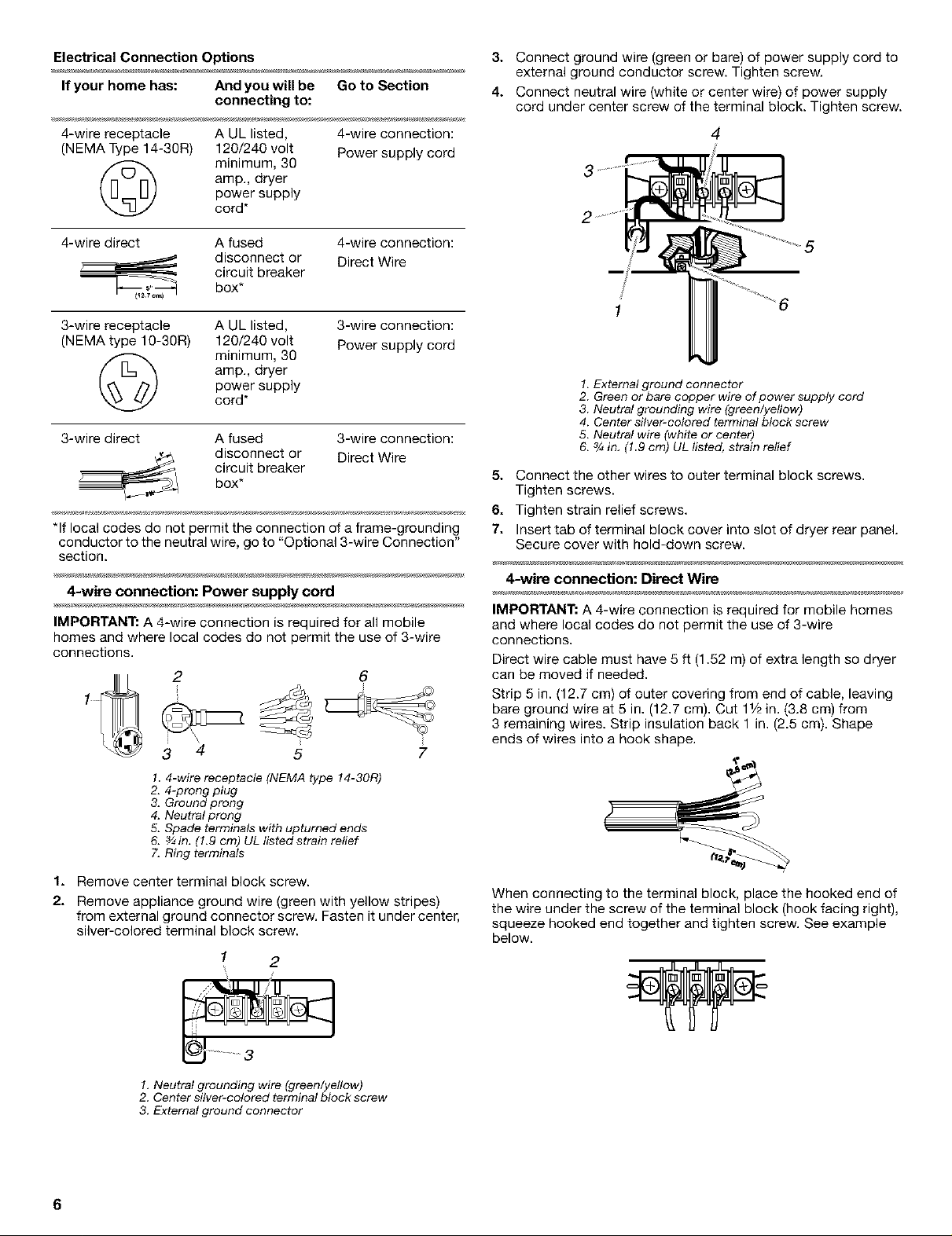
3. Connect ground wire (green or bare) of power supply cord to
external ground conductor screw. Tighten screw.
4. Connect neutral wire (white or center wire) of power supply
cord under center screw of the terminal block. Tighten screw.
4
4-wire direct A fused 4-wire connection:
disconnect or Direct Wire
circuit breaker
box*
3-wire receptacle A UL listed,
(NEMA type 10-30R) 120/240 volt
3-wire connection:
Power supply cord
amp., dryer
power supply
minimum, 30
cord*
3-wire direct A fused 3-wire connection:
disconnect or Direct Wire
circuit breaker
box*
*If local codes do not permit the connection of a frame-grounding
conductor to the neutral wire, go to "Optional 3-wire Connection"
section.
4-wire connection: Power supply cord
IMPORTANT: A 4-wire connection is required for all mobile
homes and where local codes do not permit the use of 3-wire
connections.
2
4
3
1.4-wire receptacle (NEMA type 14-30R)
2. 4-prong plug
3. Ground prong
4. Neutral prong
5. Spade terminals with upturned ends
& _in. (1.9 cm) UL listedstrain relief
7. Ring terminals
5 7
6
1. Remove center terminal block screw.
2. Remove appliance ground wire (green with yellow stripes)
from external ground connector screw. Fasten it under center,
silver-colored terminal block screw.
1 2
5
1. External ground connector
2. Green or bare copper wire of power supply cord
3. Neutral grounding wire (green/yellow)
4. Center silver-colored terminal block screw
5. Neutral wire (white or center)
6. 3/_in. (1.9 cm) UL listed, strain relief
5. Connect the other wires to outer terminal block screws.
Tighten screws.
6. Tighten strain relief screws.
7. Insert tab of terminal block cover into slot of dryer rear panel.
Secure cover with hold-down screw.
4-wire connection: Direct Wire
IMPORTANT: A 4-wire connection is required for mobile homes
and where local codes do not permit the use of 3-wire
connections.
Direct wire cable must have 5 ft (1.52 m) of extra length so dryer
can be moved if needed.
Strip 5 in. (12.7 cm) of outer covering from end of cable, leaving
bare ground wire at 5 in. (12.7 cm). Cut 11/2in. (3.8 cm) from
3 remaining wires. Strip insulation back 1 in. (2.5 cm). Shape
ends of wires into a hook shape.
When connecting to the terminal block, place the hooked end of
the wire under the screw of the terminal block (hook facing right),
squeeze hooked end together and tighten screw. See example
below.
/
1, Neutral grounding wire (green/yellow)
2. Center silver-colored terminal block screw
3. External ground connector
6
1. Remove center terminal block screw.
2. Remove appliance ground wire (green with yellow stripes)
from external ground connector screw. Fasten it under center,
silver-colored terminal block screw.
1 2
1, Neutral grounding wire (green/yellow)
2. Center silver-colored terminal block screw
3. External ground connector
3. Connect ground wire (green or bare) of power supply cable to
external ground conductor screw. Tighten screw.
4. Place the hooked end of the neutral wire (white or center wire)
of power supply cable under the center screw of terminal
block (hook facing right). Squeeze hooked end together.
Tighten screw.
3 4
2
3-wire connection: Power supply cord
Use where local codes permit connecting cabinet-ground
conductor to neutral wire.
2 4 5
3 7 6
1.3-wire receptacle (NEMA type 10-30R)
2. 3-wire plug
3. Neutral prong
4. Spade terminals with up turned ends
5, ¾in. (1.9 cm) UL ilsted strain relief
6. Ring terminals
7. Neutral (white or center wire)
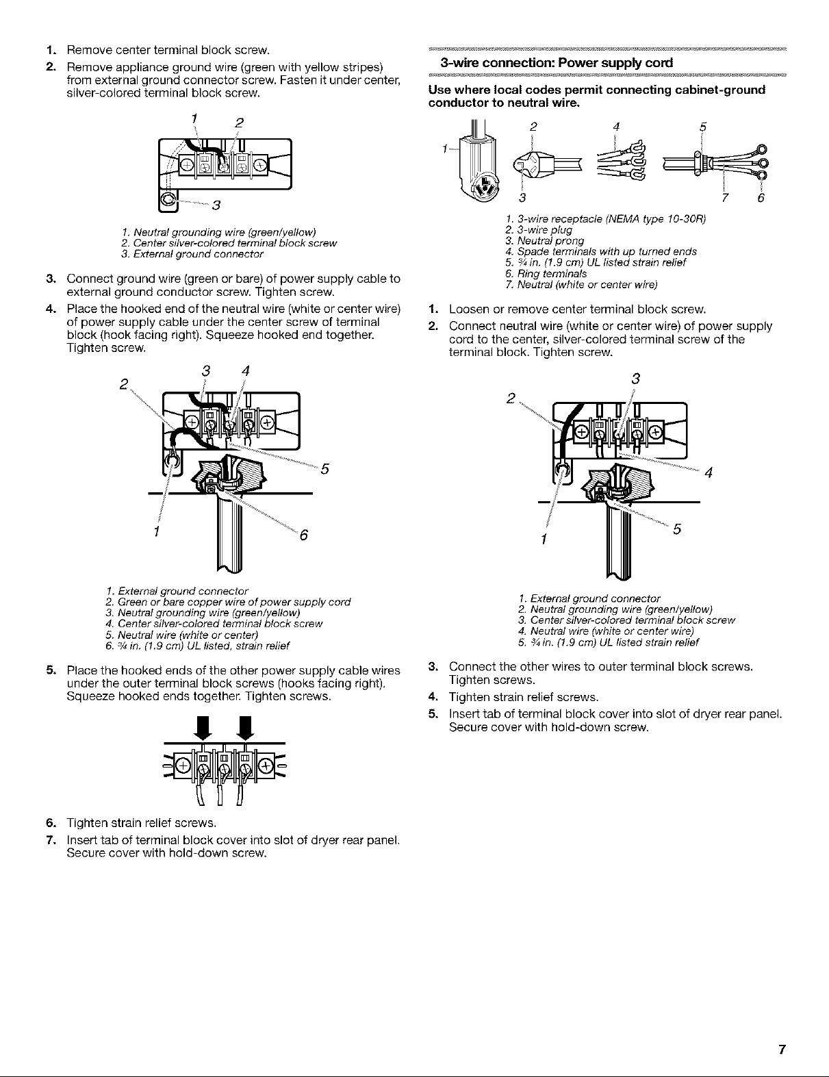
1. Loosen or remove center terminal block screw.
2. Connect neutral wire (white or center wire) of power supply
cord to the center, silver-colored terminal screw of the
terminal block. Tighten screw.
3
5
1. External ground connector
2. Green or bare copper wire of power supply cord
3. Neutral grounding wire (green/yellow)
4. Center silver-colored terminal block screw
5. Neutral wire (white or center)
6. 3/4in. (l.g cm) UL listed, strain relief
5. Place the hooked ends of the other power supply cable wires
under the outer terminal block screws (hooks facing right).
Squeeze hooked ends together. Tighten screws.
!! !!
6. Tighten strain relief screws.
7. Insert tab of terminal block cover into slot of dryer rear panel.
Secure cover with hold-down screw.
4
1. External ground connector
2. Neutral grounding wire (green/yellow)
3. Center silver-colored terminal block screw
4. Neutral wire (white or center wire)
5. _ in. (1.9 cm) UL listed strain relief
3. Connect the other wires to outer terminal block screws.
Tighten screws.
4. Tighten strain relief screws.
5. Insert tab of terminal block cover into slot of dryer rear panel.
Secure cover with hold-down screw.
7
3-wire connection: Direct Wire Optional 3-wire connection
Use where local codes permit connecting cabinet-ground
conductor to neutral wire.
Direct wire cable must have 5 ft (1.52 m) of extra length so dryer
can be moved if needed.
Strip 3V2in. (8.9 cm) of outer covering from end of cable. Strip
insulation back 1 in. (2.5 cm) If using 3-wire cable with ground
wire, cut bare wire even with outer covering. Shape ends of wires
into a hook shape.
When connecting to the terminal block, place the hooked end of
the wire under the screw of the terminal block (hook facing right),
squeeze hooked end together and tighten screw. See example
below.
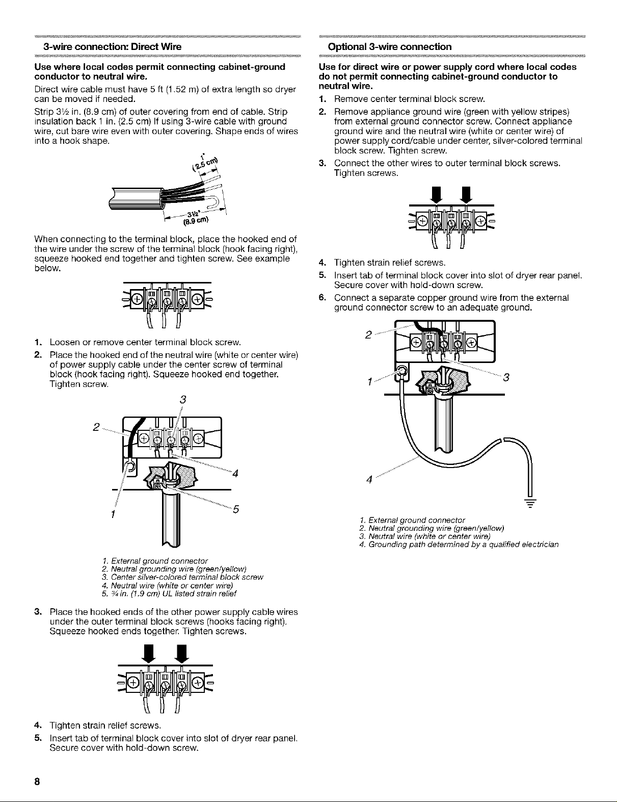
1. Loosen or remove center terminal block screw.
2. Place the hooked end of the neutral wire (white or center wire)
of power supply cable under the center screw of terminal
block (hook facing right). Squeeze hooked end together.
Tighten screw.
3
Use for direct wire or power supply cord where local codes
do not permit connecting cabinet-ground conductor to
neutral wire.
1. Remove center terminal block screw.
2. Remove appliance ground wire (green with yellow stripes)
from external ground connector screw. Connect appliance
ground wire and the neutral wire (white or center wire) of
power supply cord/cable under center, silver-colored terminal
block screw. Tighten screw.
3. Connect the other wires to outer terminal block screws.
Tighten screws.
!! 1!
4. Tighten strain relief screws.
5. Insert tab of terminal block cover into slot of dryer rear panel.
Secure cover with hold-down screw.
6. Connect a separate copper ground wire from the external
ground connector screw to an adequate ground.
1 5
1, External ground connector
2, Neutral grounding wire (green/yellow)
3. Center silver-colored terminal block screw
4. Neutral wire (white or center wire)
5, ¾ in. (1.9 cm) UL listed strain relief
3. Place the hooked ends of the other power supply cable wires
under the outer terminal block screws (hooks facing right).
Squeeze hooked ends together. Tighten screws.
!! !!
4. Tighten strain relief screws.
5. Insert tab of terminal block cover into slot of dryer rear panel.
Secure cover with hold-down screw.
8
1, External ground connector
2, Neutral grounding wire (green/yellow)
3, Neutral wire (white or center wire)
4. Grounding path determined by a qualified electrician
Fire Hazard
Use a heavy metal vent.
Do not use a plastic vent.
Do not use a metal foil vent.
Failure to follow these instructions can result in death
or fire.
WARNING: To reduce the risk of fire, this laundry center
MUST BE EXHAUSTED OUTDOORS.
4 in. (10.2 cm) heavy metal exhaust vent and clamps must be
used. DURASAFE TM venting products are recommended and are
available from your local Sears store or Sears Service Center.
DURASAFF Mvent products can be purchased from your dealer.
For further information, please call 1-800-4-MY-HOME ®
(1-800-469-4663) or visit our Internet site at www.sears.cem.
• The dryer exhaust must not be connected into any gas vent,
chimney, wall, ceiling, or a concealed space of a building.
• Do not use an exhaust hood with a magnetic latch.
• Do not install flexible metal vent in enclosed walls, ceilings or
floors.
Use clamps to seal all joints. Exhaust vent must not be
connected or secured with screws or other fastening devices
which extend into the interior of the duct. Do not use duct
tape.
IMPORTANT: Observe all governing codes and ordinances.
Improper venting can cause moisture and lint to collect
indoors, which may result in:
• Moisture damage to woodwork, furniture, paint, wail-
paper, carpets, etc.
• Housecleaning problems and health problems.
To prevent floor damage, set laundry center onto cardboard
before moving across floor. Move laundry center close to its final
location.
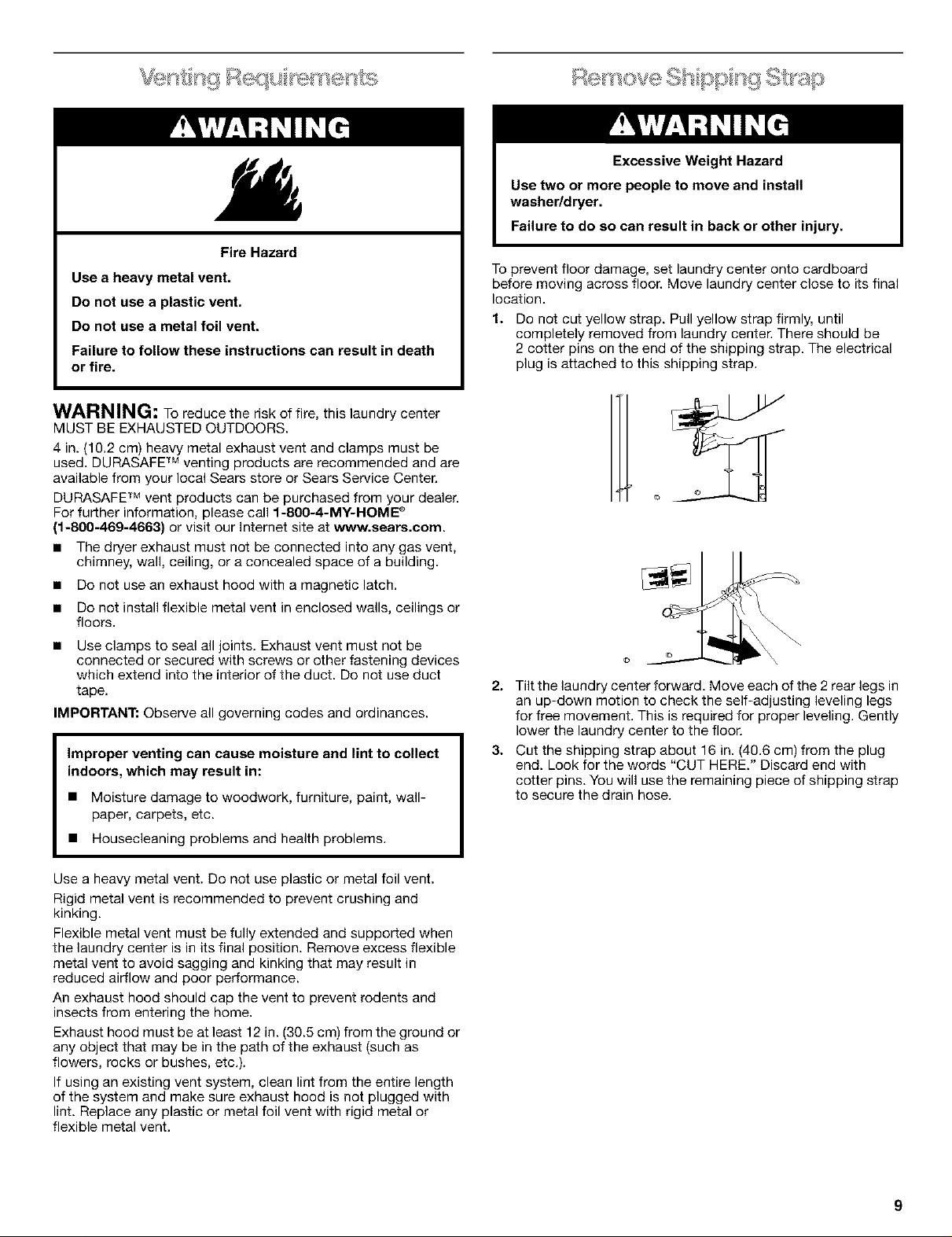
1.
Do not cut yellow strap. Pull yellow strap firmly, until
completely removed from laundry center. There should be
2 cotter pins on the end of the shipping strap. The electrical
plug is attached to this shipping strap.
2. Tilt the laundry center forward. Move each of the 2 rear legs in
an up-down motion to check the self-adjusting leveling legs
for free movement. This is required for proper leveling. Gently
lower the laundry center to the floor.
3. Cut the shipping strap about 16 in. (40.6 cm) from the plug
end. Look for the words "CUT HERE." Discard end with
cotter pins. You will use the remaining piece of shipping strap
to secure the drain hose.
Use a heavy metal vent. Do not use plastic or metal foil vent.
Rigid metal vent is recommended to prevent crushing and
kinking.
Flexible metal vent must be fully extended and supported when
the laundry center is in its final position. Remove excess flexible
metal vent to avoid sagging and kinking that may result in
reduced airflow and poor performance.
An exhaust hood should cap the vent to prevent rodents and
insects from entering the home.
Exhaust hood must be at least 12 in. (30.5 cm) from the ground or
any object that may be in the path of the exhaust (such as
flowers, rocks or bushes, etc.).
If using an existing vent system, clean lint from the entire length
of the system and make sure exhaust hood is not plugged with
lint. Replace any plastic or metal foil vent with rigid metal or
flexible metal vent.
9
Install the front leveling feet
1. Prop up the front of the laundry center about 4 in. (10.2 cm)
with a wood block or similar object. The block needs to
support the weight of the laundry center.
2. Screw the lock nut onto each foot to within 1 in. (2.5 cm) of
the base.
(2.5 cm)
3. Screw the feet into the correct holes at the front corner of the
laundry center until the nuts touch the washer.
NOTE: Do not tighten the nuts until the laundry center is level.
4. Tilt the laundry center back and remove the wood block.
Gently lower the laundry center to the floor.
Proper connection of the drain hose protects your floors from
damage due to water leakage. To prevent the drain hose from
coming off or leaking, it must be installed per the following
instructions:
IMPORTANT: Toensure proper installation, this procedure must
be followed exactly.
1. Check the drain hose to see whether it is the proper length.
2. Wet the inside of the straight end of the drain hose with tap
water. DO NOT USE ANY OTHER LUBRICANT.
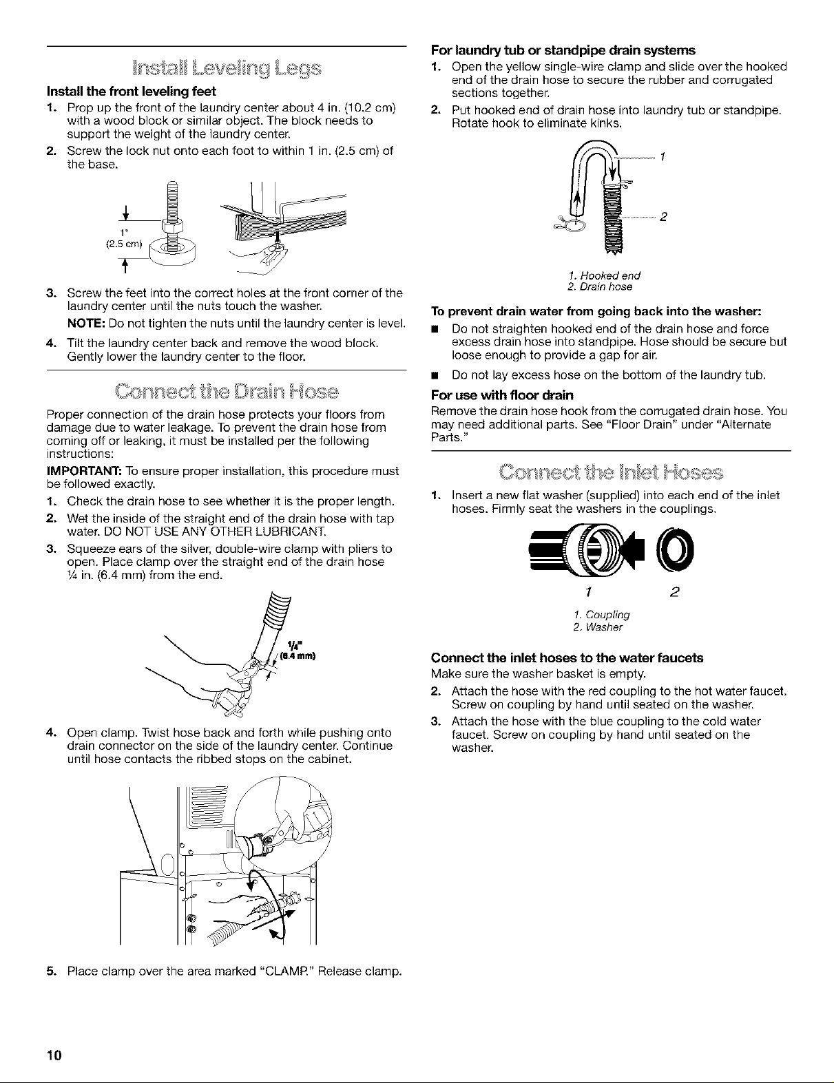
3. Squeeze ears of the silver, double-wire clamp with pliers to
open. Place clamp over the straight end of the drain hose
_/_in. (6.4 ram) from the end.
For laundry tub or standpipe drain systems
1. Open the yellow single-wire clamp and slide over the hooked
end of the drain hose to secure the rubber and corrugated
sections together.
2. Put hooked end of drain hose into laundry tub or standpipe.
Rotate hook to eliminate kinks.
1. Hooked end
2. Drain hose
To prevent drain water from going back into the washer:
• Do not straighten hooked end of the drain hose and force
excess drain hose into standpipe. Hose should be secure but
loose enough to provide a gap for air.
• Do not lay excess hose on the bottom of the laundry tub.
For use with floor drain
Remove the drain hose hook from the corrugated drain hose, You
may need additional parts. See "Floor Drain" under "Alternate
Parts."
1.
Insert a new flat washer (supplied) into each end of the inlet
hoses. Firmly seat the washers in the couplings.
1 2
mm)
4. Open clamp. Twist hose back and forth while pushing onto
drain connector on the side of the laundry center. Continue
until hose contacts the ribbed stops on the cabinet,
5. Place clamp over the area marked "CLAMR" Release clamp.
1.Coupling
2. Washer
Connect the inlet hoses to the water faucets
Make sure the washer basket is empty.
2. Attach the hose with the red coupling to the hot water faucet,
Screw on coupling by hand until seated on the washer.
3. Attach the hose with the blue coupling to the cold water
faucet. Screw on coupling by hand until seated on the
washer.
10
 Loading...