

Kenmore 110.81422, 110.81432 Use & Care Manual

Use & Care Guide & Installation Instructions
Manual de uso y cuidado y las Instrucciones de instalación
Guide d’utilisation et d’entretien et Instructions pour l’installation
English / Español / Français
Table of Contents...2
Índice...38
Table des matières...74
Models/Modelos/Modèles : 110.81422, 110.81432
Kenmore®
24" (61 cm) Wide Laundry Center
Washer – Electric Dryer
Centro de lavandería de 24" (61 cm) de ancho
Lavadora – Secadora eléctrica
Centre de buanderie de 24" (61 cm) de large
Laveuse – Sécheuse électrique
P/N W10746859A
Sears Brands Management Corporation
Hoffman Estates, IL 60179 U.S.A.
www.kenmore.com
www.sears.com
Sears Canada Inc.
Toronto, Ontario, Canada M5B 2B8
www.sears.ca

TABLE OF CONTENTS
WASHER/DRYER SAFETY ......................................................3
INSTALLATION INSTRUCTIONS ............................................ 5
Tools and Parts .....................................................................5
Alternate Parts ......................................................................6
Location Requirements ........................................................6
Drain System .........................................................................7
Electrical Requirements – 240 Volt Models ....................7
Electrical Requirements – 120 Volt Models .....................9
Electrical Connection – 240 Volt Models ...................... 10
Venting Requirements ........................................................ 16
Install Leveling Legs ........................................................... 17
Remove Foam Packing ...................................................... 17
Connect Drain Hose...........................................................17
Connect Inlet Hoses ........................................................... 18
Secure Drain Hose ............................................................. 19
Plan Vent System .............................................................. 20
Install Vent System ............................................................. 21
Connect Vent ...................................................................... 21
Level Laundry Center ........................................................22
Complete Installation ........................................................22
WASHER USE .......................................................................... 23
Control Panel and Features ..............................................23
Starting Your Washer ........................................................23
Cycles ................................................................................. 24
Rinse and Spin ................................................................... 24
Drain and Spin .................................................................. 24
Understanding Washer Cycles .........................................25
Normal Sounds...................................................................25
LAUNDRY TIPS ........................................................................25
Loading ...............................................................................25
DRYER USE ...............................................................................26
Control Panel and Features ..............................................26
Starting Your Dryer ........................................................... 27
Stopping and Restarting .................................................. 27
Loading .............................................................................. 27
Drying, Cycle, and Temperature Tips ............................. 27
Cycles ..................................................................................28
LAUNDRY CENTER CARE ...................................................... 28
Cleaning the Laundry Center Location ...........................28
Cleaning Your Washer ......................................................28
Water Inlet Hoses ..............................................................28
Cleaning the Lint Screen ...................................................29
Cleaning the Dryer Interior ..............................................29
Removing Accumulated Lint .............................................29
Vacation, Storage, and Moving Care .............................29
TROUBLESHOOTING WASHER ............................................ 31
TROUBLESHOOTING DRYER ...............................................35
PROTECTION AGREEMENTS ...............................................37
WARRANTY .............................................................................37
SERVICE NUMBERS ................................................Back Cover
2
WASHER/DRYER SAFETY
3
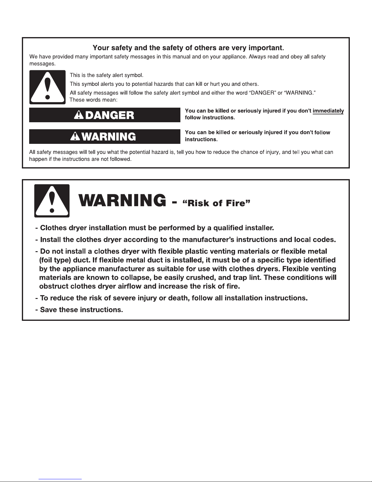
IMPORTA NT SAFETY INSTRUCTIONS
To reduce the risk of fire, electric shock, or injury to persons when using the washer/dryer, follow basic
WARNING:
precautions, including the following:
Read all instructions before using the washer/dryer.
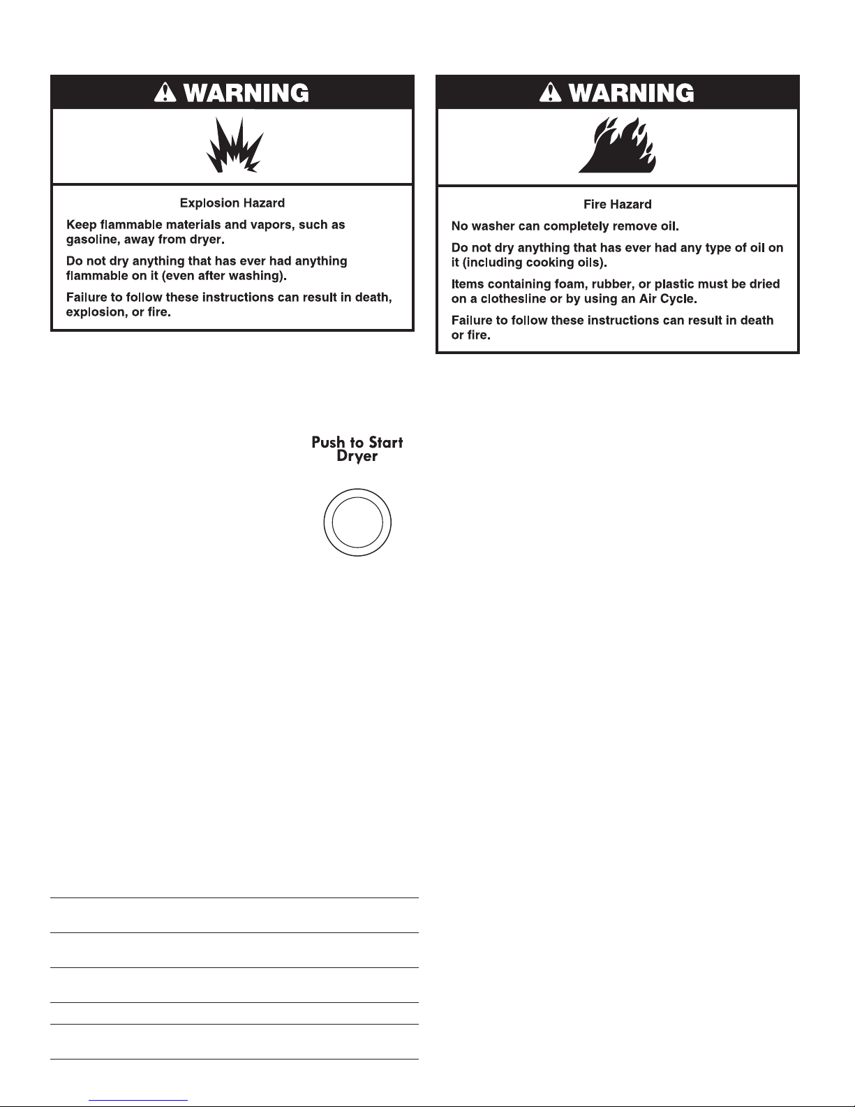
Do not place items exposed to cooking oils in your dryer.
Items contaminated with cooking oils may contribute to a
chemical reaction that could cause a load to catch fire.
Do not wash or dry articles that have been previously
cleaned in, washed in, soaked in, or spotted with gasoline,
dry-cleaning solvents, other flammable, or explosive
substances as they give off vapors that could ignite or
explode.
Do not add gasoline, dry-cleaning solvents, or other
flammable, or explosive substances to the wash water.
These substances give off vapors that could ignite or
explode.
Do not allow children to play on or in the washer/dryer.
Close supervision of children is necessary when the
washer/dryer is used near children.
Before the washer/dryer is removed from service or
discarded, remove the doors to the washer/dryer
compartments.
Do not reach into the washer/dryer if the tub, agitator or
drum is moving.
Do not install or store the washer/dryer where it will be
exposed to the weather.
Do not tamper with controls.
Clean dryer lint screen before or after each load.
Under certain conditions, hydrogen gas may be produced in
a hot water system that has not been used for 2 weeks or
more. HYDROGEN GAS IS EXPLOSIVE. If the hot water
system has not been used for such a period, before using
the washing machine, turn on all hot water faucets and let
the water flow from each for several minutes. This will
release any accumulated hydrogen gas. As the gas is
flammable, do not smoke or use an open flame during this
time.
Do not repair or replace any part of the washer/dryer or
attempt any servicing unless specifically recommended in
this Use and Care Guide or in published user-repair
instructions that you understand and have the skills to carry
out.
Do not use fabric softeners or products to eliminate static
unless recommended by the manufacturer of the fabric
softener or product.
Do not use heat to dry articles containing foam rubber or
similarly textured rubber-like materials.
Keep area around the exhaust opening and adjacent
surrounding areas free from the accumulation of lint, dust,
and dirt.
The interior of the machine and dryer exhaust vent should
be cleaned periodically by qualified service personnel.
See "Electrical Requirements" section for grounding
instructions.
SAVE THESE INSTRUCTIONS
IMPORTANT: When discarding or storing your old clothes dryer, remove the door.
4
INSTALLATION INSTRUCTIONS
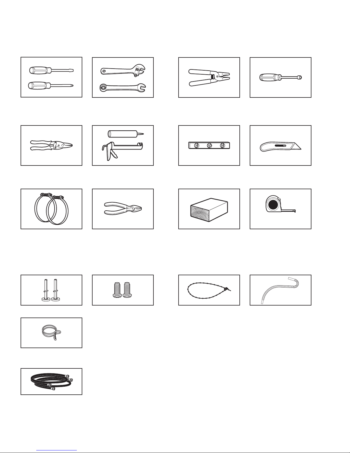
TOOLS AND PARTS
Gather the required tools and parts before starting installation. Read and follow the instructions provided with any tools listed here.
Tools needed:
#2 Phillips and at-
blade screwdriver
Tin snips (for new vent
installations)
Vent clamps
Adjustable wrench that
opens to 1" (25 mm) or
9/16" open-end wrench
(for adjusting dryer feet)
Caulking gun and
compound (for installing
new exhaust vent)
Wire stripper (direct wire
installations)
Level
Wood block
(for leveling)
Parts supplied:
Remove parts package from the washer basket. Check that all parts were included.
1/4" (6 mm) nut
driver or socket wrench
(recommended)
Knife
Ruler or measuring tapePliers
Front leveling legs (2)
Silver, double-wire hose clamp
Parts needed: (Not supplied)
Check local codes, electrical supply, and venting, and read “Electrical Requirements” and “Venting
Requirements” before purchasing parts.
Mobile home installations require metal exhaust system hardware available for purchase from your
local Sears store or Sears Service Center. For further information, please call 1-800-4-MY-HOME®
(1-800-469-4663).
Inlet hoses with flat washers
Removable tie strapRear leveling legs (2)
Drain hose
5
ALTERNATE PARTS
(606 mm)
(816 mm)
3" (76 mm)
3" (76 mm)
Parts listed are available from your local Sears store or
Sears Service Center. For further information, please call
1-800-4-MY-HOME® (1-800-469-4663).
If you have: You will need to buy:
Laundry tub or Sump pump system (if not already
standpipe taller than available)
96" (2.4 m)
1" (25 mm) 2" (51 mm) diameter to 1" (25 mm)
diameter standpipe diameter standpipe adapter,
Part Number 3363920
Overhead sewer Standard 20 gal. (76 L) 34" (864 mm)
tall drain tub or utility sink and sump
pump (available from local plumbing
suppliers)
Floor drain Siphon break, Part Number 285320,
additional drain hose, Part Number
285702, and connector kit, Part
Number 285442
Drain hose too short Drain hose, Part Number 285664
and connector kit, Part Number 285442
Lint clogged drain Drain protector, Part Number 367031
Water faucets 2 longer water ll hoses:
beyond reach 6 ft (1.8 m), Part Number 76314,
of ll hoses 10 ft (3.0 m), Part Number 350008
LOCATION REQUIREMENTS
Do not operate your washer in temperatures at or below 32ºF
(0ºC). Some water can remain in the washer and can cause
damage in low temperatures. See “Vacation, Storage, and Moving
Care” for winterizing information.
Do not operate your dryer at temperatures below 45°F (7°C). At
lower temperatures, the dryer might not shut o at the end of an
automatic cycle. This can result in longer drying times.
Check code requirements. Some codes limit, or do not permit,
installation of the Laundry Center in garages, closets, mobile
homes, or sleeping quarters. Contact your local building inspector.
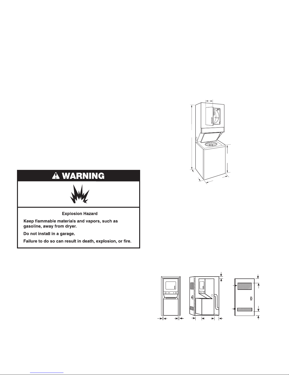
Installation Clearances
The location must be large enough to allow the dryer door
to open fully.
Laundry Center Dimensions
71 ¾"
(1.82 m)
3
/8"
15
(390 mm)
32
1
/8"
You will need
■ A location that allows for proper exhaust installation. See
“Venting Requirements”.
■ For 240 volt models, a separate 30-amp circuit. For 120 volt
models, a 120 volt, 60 Hz., AC only, 15- or 20-amp circuit.
■ If using a power supply cord on 240 volt models, and for 120
volt models, a grounded electrical outlet located within 2 ft.
(610 mm) of either side of the Laundry Center. See “Electrical
Requirements”.
■ A sturdy oor to support the Laundry Center weight (Laundry
Center, water, and load) of 500 lbs (226.8 kg).
■ A level oor with a maximum slope of 1" (25 mm) under
entire Laundry Center. Clothes may not tumble properly and
automatic sensor cycles may not operate correctly if Laundry
Center is not level. Installing on carpet is not recommended.
■ A water heater set to deliver 120°F (49°C) water to the washer.
■ Hot and cold water faucets located within 4 ft (1.2 m) of the
hot and cold water ll valves, and water pressure of 5-100 psi
(34.5-689.6 kPa).
The Laundry Center must not be installed or stored in an area
where it will be exposed to water and/or weather.
6
*27 ¼"
(692 mm)
*23
7
/8"
** Most installations require a minimum 5" (127 mm) clearance behind
the dryer for the exhaust vent with elbow. See “Venting Requirements”.
Minimum spacing for recessed area or closet installation
The following spacing dimensions are recommended for this
Laundry Center. This Laundry Center has been tested for spacing
of 0" (0 mm) clearance on the sides, rear, and top. Recommended
spacing should be considered for the following reasons:
■ Additional spacing should be considered for ease of installation
and servicing.
■ Additional clearances might be required for wall, door, and
oor moldings.
■ Additional spacing on all sides of the Laundry Center is
recommended to reduce noise transfer.
■ For closet installation, with a door, minimum ventilation openings
in the top and bottom of the door are required. Louvered doors
with equivalent ventilation openings are acceptable.
12"
(305 mm)
2
48 in.
(310 cm2)
2
24 in.
(155 cm2)
23 7/8"
"
1
(25 mm)
(606 mm)
1
"
(25 mm)
1"*
(25 mm)
27 ¼"
(692 mm)
A B C
A. Recessed area
B. Side view – closet or confined area
C. Closet door with vents
** Required spacing
** Rear clearance may be 0" (0 mm) when house exhaust system
is lined up directly with dryer exhaust.
5"**
(127 mm)
Mobile Home – Additional Installation Requirements
(991 mm)
This Laundry Center is suitable for mobile home installations. The
installation must conform to the Manufactured Home Construction
and Safety Standard, Title 24 CFR, Part 3280 (formerly the
Federal Standard for Mobile Home Construction and Safety,
Title 24, HUD Part 280) or the Canadian Manufactured Home
Standard, CAN/CSA-Z240 MH.
Mobile home installations require:
■ Metal exhaust system hardware, which is available for
purchase from your local Sears store or Sears Service Center.
■ Special provisions must be made in mobile homes to introduce
outside air into the dryer. The opening (such as a nearby
window) should be at least twice as large as the dryer exhaust
opening.
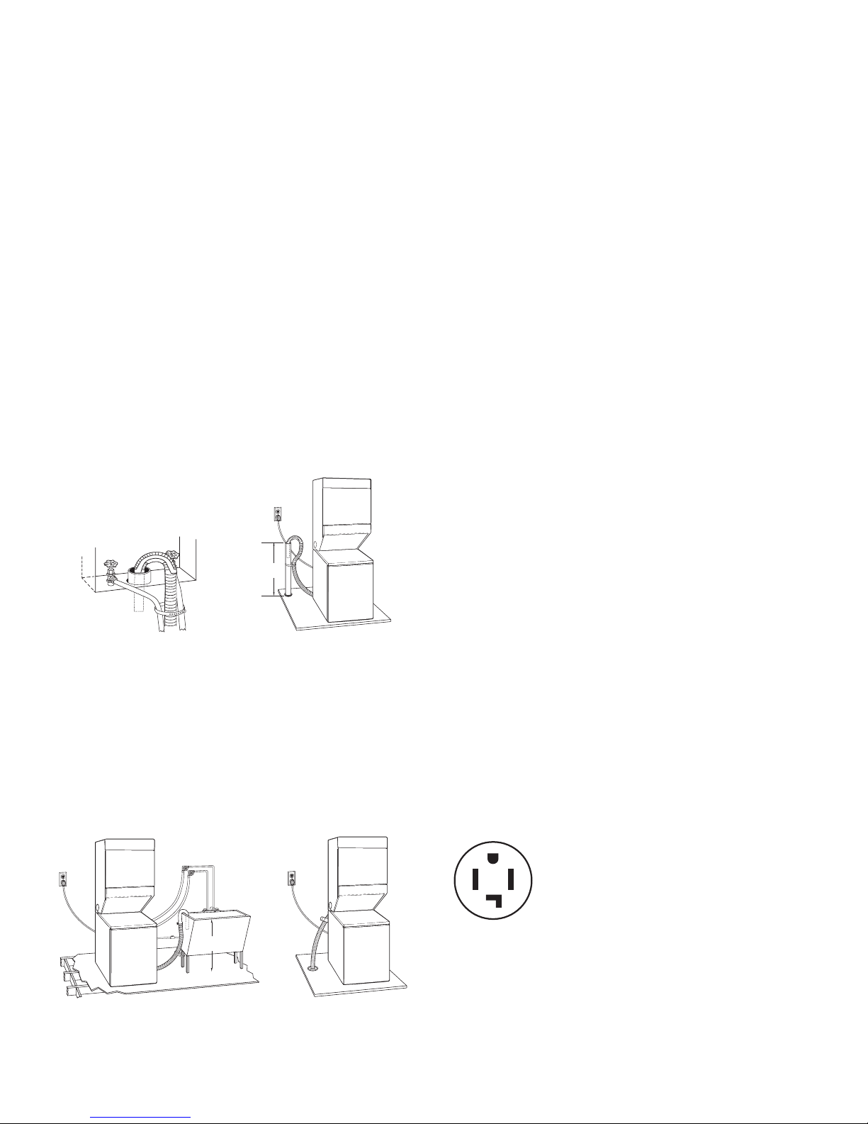
DRAIN SYSTEM
The Laundry Center can be installed using the standpipe drain
system (oor or wall), the laundry tub drain system, or the oor
drain system. Select the drain hose installation method you need.
See “Alternate Parts”.
Standpipe drain system – wall or oor (views A & B)
The standpipe drain requires a minimum diameter standpipe of 2"
(51 mm). The minimum carry-away capacity can be no less than
17 gal. (64 L) per minute. A 2" (51 mm) diameter to 1" (25 mm)
diameter standpipe adapter kit is available. See “Alternate Parts”.
The top of the standpipe must be at least 39" (991 mm) high and
no higher than 96" (2.4 m) from the bottom of the washer.
39"
A B
Laundry tub drain system (view C)
The laundry tub needs a minimum 20 gal. (76 L) capacity. The top
of the laundry tub must be at least 34" (864 mm) above the oor
and no higher than 96" (2.4 m) from the bottom of the washer.
Floor drain system (view D)
The oor drain system requires a siphon break that may be
purchased separately. See “Alternate Parts”.
The siphon break must be a minimum of 28" (710 mm) from
the bottom of the washer. Additional hoses might be needed.
34
"
(864 mm)
ELECTRICAL REQUIREMENTS – 240 VOLT MODELS
(U.S.A.)
It is your responsibility
■ To contact a qualied electrical installer.
■ To be sure that the electrical connection is adequate and in
conformance with the National Electrical Code, ANSI/NFPA
70-latest edition and all local codes and ordinances.
A copy of the above code standards can be obtained from:
National Fire Protection Association, One Batterymarch Park,
Quincy, MA 02269.
■ To supply the required 3 or 4 wire, single phase, 240 volt, 60
Hz., AC only electrical supply (or 3 or 4 wire, 208 volt electrical
supply, if specied on the serial/rating plate) on a separate 30amp circuit, fused on both sides of the line. A time-delay fuse
or circuit breaker is recommended. Connect to an individual
branch circuit. Do not have a fuse in the neutral or grounding
circuit.
■ Do not use an extension cord.
■ If codes permit and a separate ground wire is used, it is
recommended that a qualied electrician determine that the
ground path is adequate.
Electrical Connection
To properly install your Laundry Center, you must determine the
type of electrical connection you will be using and follow the
instructions provided for it here.
■ This dryer is manufactured ready to install with a 3-wire
electrical supply connection. The neutral ground wire is
permanently connected to the neutral conductor (white wire)
within the dryer. If the dryer is installed with a 4-wire electrical
supply connection, the neutral ground wire must be removed
from the internal ground connector (green screw), and secured
under the neutral terminal (center or white wire) of the terminal
block. When the neutral ground wire is secured under the
neutral terminal (center or white wire) of the terminal block,
the dryer cabinet is isolated from the neutral conductor.
■ If local codes do not permit the connection of a neutral ground
wire to the neutral wire, see “Optional 3-wire connection” in
“Electrical Connection” section.
■ Use a 4-wire conductor cord when the dryer is installed in
a mobile home or an area where local codes do not permit
grounding through the neutral.
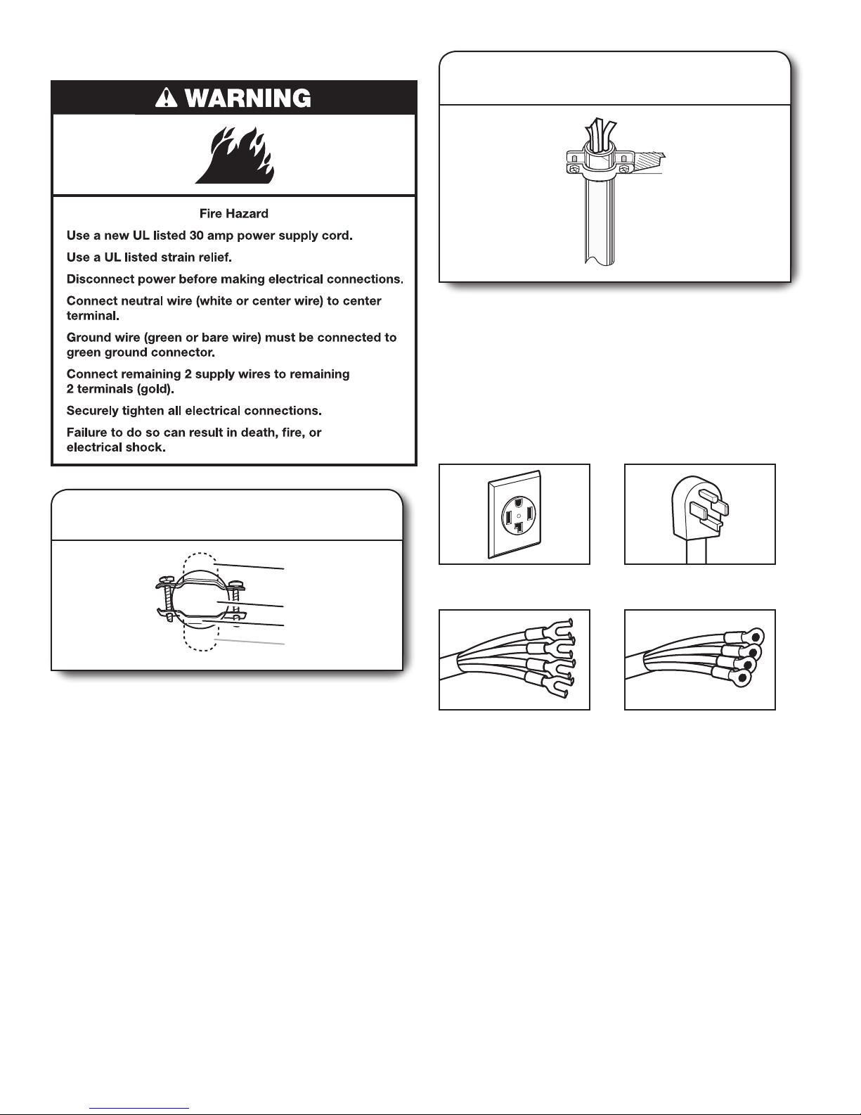
If using a power supply cord:
■ Use a UL listed power supply cord kit marked for use with
clothes dryers. The kit should contain:
■ A UL listed 30-amp power supply cord, rated 240 volt
minimum. The cord should be type SRD or SRDT and be at least
4 ft (1.22 m) long. The wires that connect to the dryer must end
in ring terminals or spade terminals with upturned ends.
■ A UL listed strain relief.
If your outlet looks like this:
Then choose a 4-wire power supply cord with
ring or spade terminals and UL listed strain
relief. The 4-wire power supply cord, at least
4 ft (1.22 m) long, must have four 10-gauge
copper wires and match a 4-wire receptacle of
NEMA Type 14-30R. The ground wire (ground
4-wire
receptacle
(14-30R)
conductor) may be either green or bare. The
neutral conductor must be identied by a white
cover.
C D
7
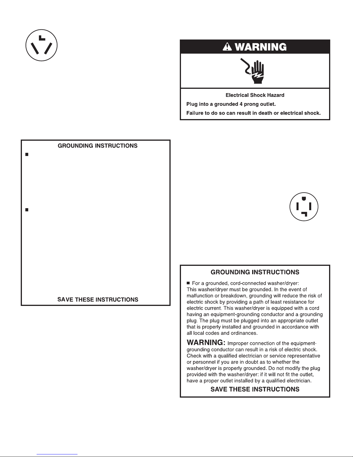
If your outlet looks like this:
Then choose a 3-wire power supply cord with
ring or spade terminals and UL listed strain
relief. The 3-wire power supply cord, at least 4 ft
(1.22 m) long, must have three 10-gauge copper
wires and match a 3-wire receptacle of NEMA
Type 10-30R.
3-wire
receptacle
(10-30R)
If connecting by direct wire:
Power supply cable must match power supply (4-wire or 3-wire)
and be:
■ Flexible armored cable or nonmetallic sheathed copper cable
(with ground wire), protected with exible metallic conduit.
All current-carrying wires must be insulated.
■ 10-gauge solid copper wire. (Do not use aluminum.)
■ At least 5 ft (1.52 m) long.
For a grounded, cord-connected washer/dryer:
This washer/dryer must be grounded. In the event of
malfunction or breakdown, grounding will reduce the risk of
electric shock by providing a path of least resistance for
electric current. This washer/dryer uses a cord having an
equipment-grounding conductor and a grounding plug. The
plug must be plugged into an appropriate outlet that is
properly installed and grounded in accordance with all local
codes and ordinances.
For a permanently connected washer/dryer:
This washer/dryer must be connected to a grounded metal,
permanent wiring system, or an equipment-grounding
conductor must be run with the circuit conductors and
connected to the equipment-grounding terminal or lead on
the washer/dryer.
WARNING: Improper connection of the equipment-
grounding conductor can result in a risk of electric shock.
Check with a qualified electrician or service representative or
personnel if you are in doubt as to whether the washer/dryer
is properly grounded. Do not modify the plug on the power
supply cord: if it will not fit the outlet, have a proper outlet
installed by a qualified electrician.
ELECTRICAL REQUIREMENTS – 240 VOLT MODELS
(CANADA)
It is your responsibility
■ To contact a qualied electrical installer.
■ To be sure that the electrical connection is adequate and in
conformance with the Canadian Electrical Code, C22.1 – latest
edition and all local codes A copy of above codes standard
may be obtained from: Canadian Standards Association, 178
Rexdale Blvd., Toronto, ON M9W 1R3 CANADA.
■ To supply the required 4 wire, single-phase, 240 volt, 60 Hz.,
AC-only electrical supply on a separate 30-amp circuit, fused
on both sides of the line. A time-delay fuse or circuit breaker is
recommended. Connect to an individual branch circuit.
■ This dryer is equipped with a CSA
International Certied Power Cord
intended to be plugged into a
standard 14-30R wall receptacle.
The cord is 5 ft. (1.52 m) long.
Be sure wall receptacle is within
reach of laundry center’s location.
■ If using a replacement power supply cord, it is recommended
that you use Power Supply Cord Replacement Part Number
9831317.
■ For further information, please reference service numbers
located on the back cover.
4-wire receptacle (14-30R)
8
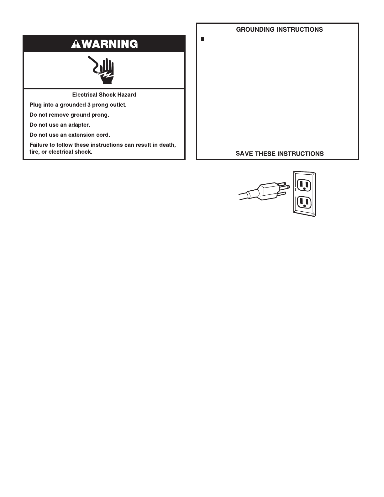
ELECTRICAL REQUIREMENTS – 120 VOLT MODELS
For a grounded, cord-connected washer/dryer:
This washer/dryer must be grounded. In the event of
malfunction or breakdown, grounding will reduce the risk of
electric shock by providing a path of least resistance for
electric current. This washer/dryer uses a cord having an
equipment-grounding conductor and a grounding plug. The
plug must be plugged into an appropriate outlet that is
properly installed and grounded in accordance with all local
codes and ordinances.
■ A 120 volt, 60 Hz., AC only, 15- or 20-amp fused electrical
supply is required.
■ This Laundry Center is equipped with a power supply cord
having a 3 prong grounding plug.
■ Be sure that the electrical connection is adequate and in
conformance with the National Electrical Code, ANSI/NFPA
70-latest edition, or Canadian Electrical Code, C22.1 – latest
edition and all local codes and ordinances.
A copy of the above code standards can be obtained from:
National Fire Protection Association, One Batterymarch
Park, Quincy, MA 02269 (U.S.A.), or Canadian Standards
Association, 178 Rexdale Blvd., Toronto, ON M9W 1R3
CANADA.
■ A time-delay fuse or circuit breaker is recommended. Be sure
fuse or circuit breaker matches the rating of your line.
■ Use a separate circuit serving only your dryer.
■ To minimize possible shock hazard, the cord must be plugged
into a mating, 3 prong, grounding-type outlet, grounded in
accordance with local codes and ordinances. If a mating outlet
is not available, it is the personal responsibility and obligation
of the customer to have the properly grounded outlet installed
by a qualied electrician.
■ If codes permit and a separate ground wire is used, it is
recommended that a qualied electrician determine that the
ground path is adequate.
■ Do not ground to a gas pipe.
■ Do not use an extension cord.
■ Do not have a fuse in the neutral or ground circuit.
■ Check with a qualied electrician if you are not sure the
Laundry Center is properly grounded.
WARNING:
grounding conductor can result in a risk of electric shock.
Check with a qualified electrician or service representative or
personnel if you are in doubt as to whether the washer/dryer
is properly grounded. Do not modify the plug on the power
cord: if it will not fit the outlet, have a proper outlet installed
by a qualified electrician.
Improper connection of the equipment-
9
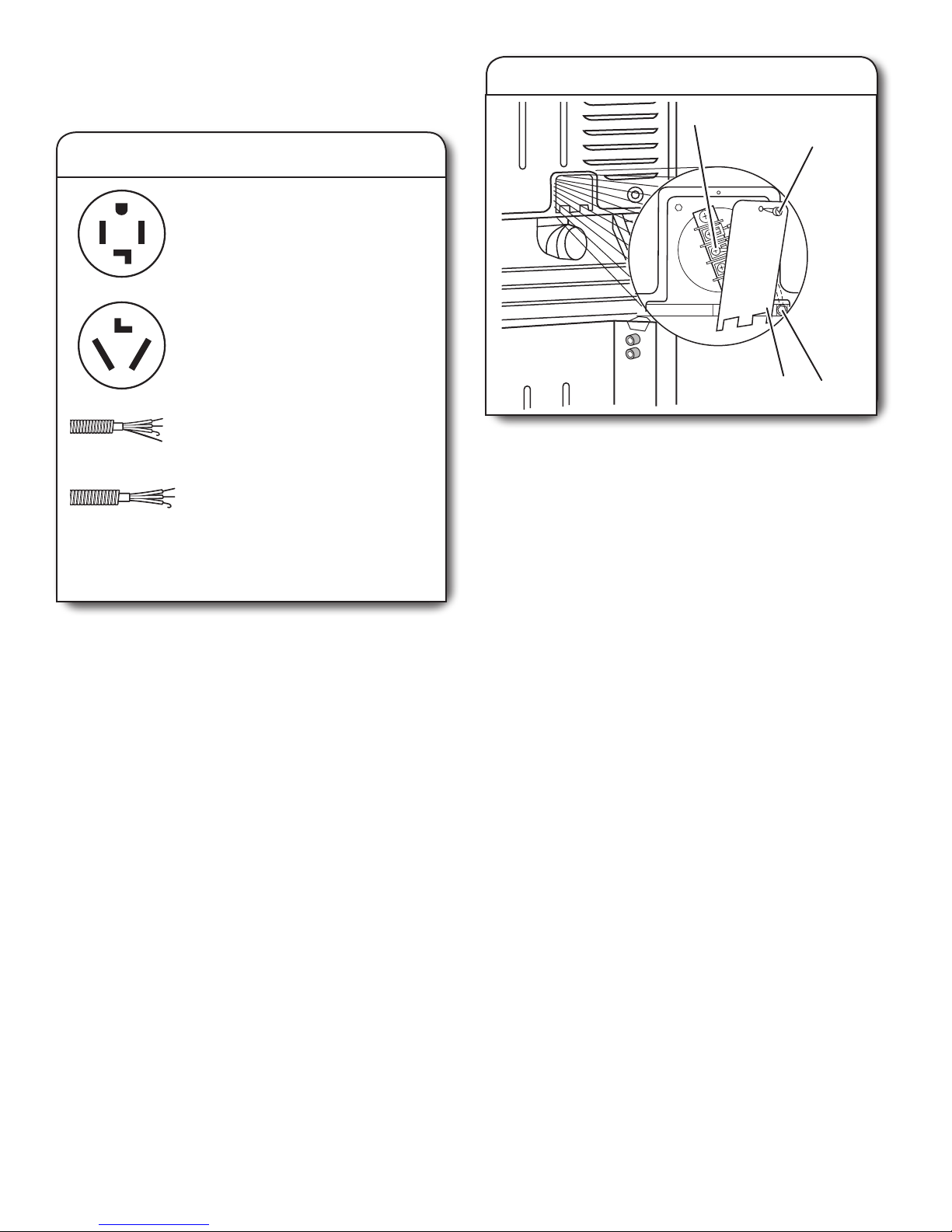
ELECTRICAL CONNECTION – 240 VOLT MODELS
(U.S.A ONLY)
2. Remove terminal block cover
Electrical Options
1. Choose electrical connection type
Power supply cord 4-wire receptacle
(NEMA Type 14-30R):
Go to Power Supply Cord Connection.
Power supply cord 3-wire receptacle
(NEMA Type 10-30R):
Go to Power Supply Cord Connection.
4-wire direct connection:
Go to Direct Wire Connection.
3-wire direct connection:
Go to Direct Wire Connection.
NOTE: If local codes do not permit connection of a
cabinet-ground conductor to the neutral wire, go to
“Optional 3-wire connection” section.
A
B
D
C
Before you start, disconnect power. Remove hold-down screw
(B) and terminal block cover (C).
A. Center terminal block screw
B. Hold-down screw
C. Terminal block cover
D. External ground conductor screw
10
Power Supply Cord Connection
A
B
C
D
2. Attach power supply cord
to strain relief
Put power supply cord through the strain relief. Be sure that
the wire insulation on the power supply cord is inside the strain
relief. The strain relief should have a tight t with the dryer
cabinet and be in a horizontal position. Do not further tighten
strain relief screws at this point.
4-wire Power Supply Cord Connection
IMPORTANT: A 4-wire connection is required for mobile
homes and where local codes do not permit the use of
3-wire connections.
1. Attach power supply cord
strain relief
Remove the screws from a 3/4" (19 mm) UL listed strain relief
(UL marking on strain relief). Put the tabs of the two clamp
sections (C) into the hole below the terminal block opening
(B) so that one tab is pointing up (A) and the other is pointing
down (D), and hold in place. Tighten strain relief screws just
enough to hold the two clamp sections (C) together.
A. Strain relief tab pointing up
B. Hole below terminal block opening
C. Clamp section
D. Strain relief tab pointing down
4-wire receptacle
(NEMA type 14-30R)
Spade terminals
with upturned ends
4-prong plug
Ring terminals
11
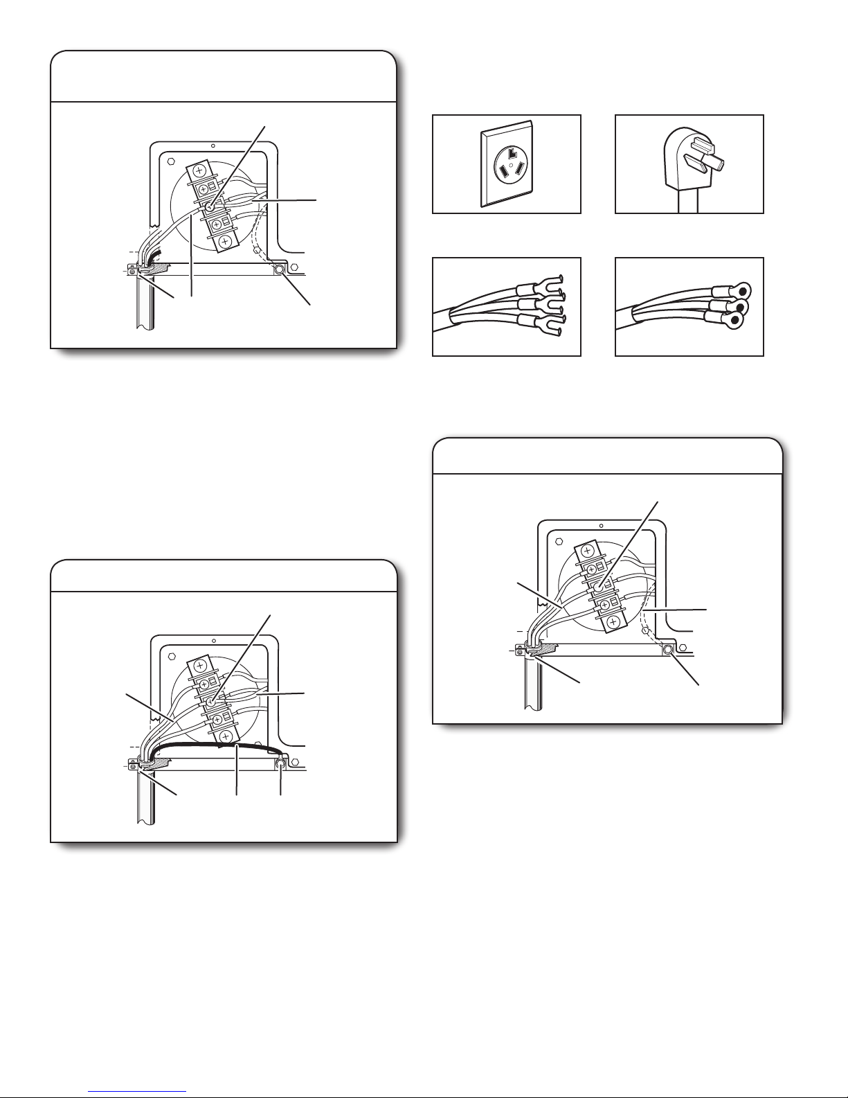
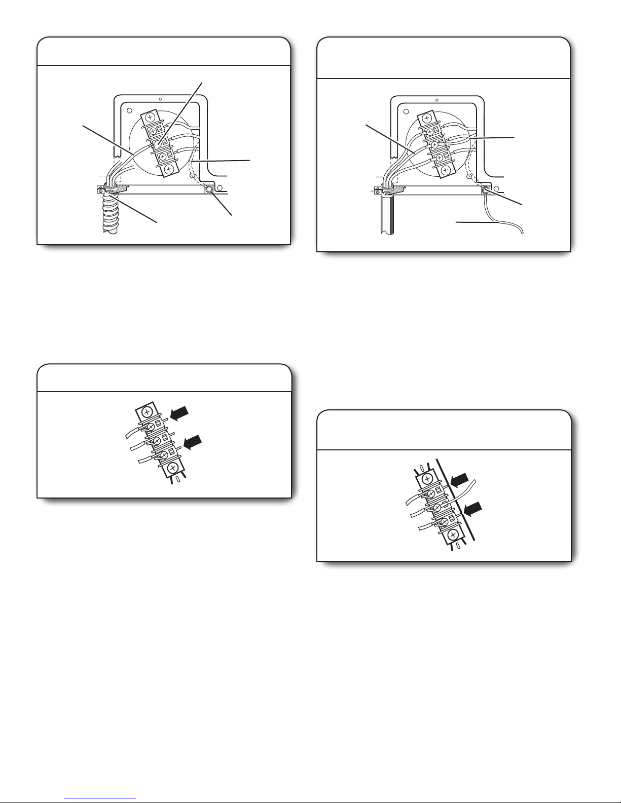
1. Connect neutral ground wire
A
B
B
and neutral wire
3-wire Power Supply Cord Connection
Use where local codes permit connecting cabinet-ground
conductor to neutral wire.
E
D
Remove center terminal block screw. Remove neutral ground
wire from external ground conductor screw. Connect neutral
ground wire and the neutral wire (white or center wire)
of power supply cord under center terminal block screw.
Tighten screw.
A. Center terminal block screw
B. Neutral ground wire
C. External ground conductor screw – Dotted
line shows position of NEUTRAL ground
wire before being moved to center terminal
block screw.
D. Neutral wire (white or center wire)
E. 3/4" (19 mm) UL listed strain relief
C
2. Connect ground wire
3-wire receptacle
(NEMA type 10-30R)
Spade terminals
with upturned ends
1. Connect neutral wire
A
3-prong plug
Ring terminals
B
C
A
F
Connect ground wire (green or bare) of power supply cord
to external ground conductor screw. Tighten screw.
A. Neutral wire (white or center wire)
B. Center terminal block screw
C. Neutral ground wire
D. External ground conductor screw
E. Ground wire (green or bare) of power
supply cord
F. 3/4" (19 mm) UL listed strain relief
Connect the other wires to outer terminal block screws. Tighten
screws. Tighten strain relief screws. Insert tab of terminal block
cover into slot of dryer rear panel. Secure cover with hold down
screw. Now go to “Venting Requirements”.
12
E
D
C
Loosen or remove center terminal block screw. Connect neutral
wire (white or center wire) of power supply cord to the center
terminal screw of the terminal block. Tighten screw.
A. Neutral wire (white or center wire)
B. Center terminal block screw
C. Neutral ground wire
D. External ground conductor screw
E. 3/4" (19 mm) UL listed strain relief
Connect the other wires to outer terminal block screws. Tighten
screws. Tighten strain relief screws. Insert tab of terminal block
cover into slot of dryer rear panel. Secure cover with hold-down
screw. Now go to “Venting Requirements”.
E
D
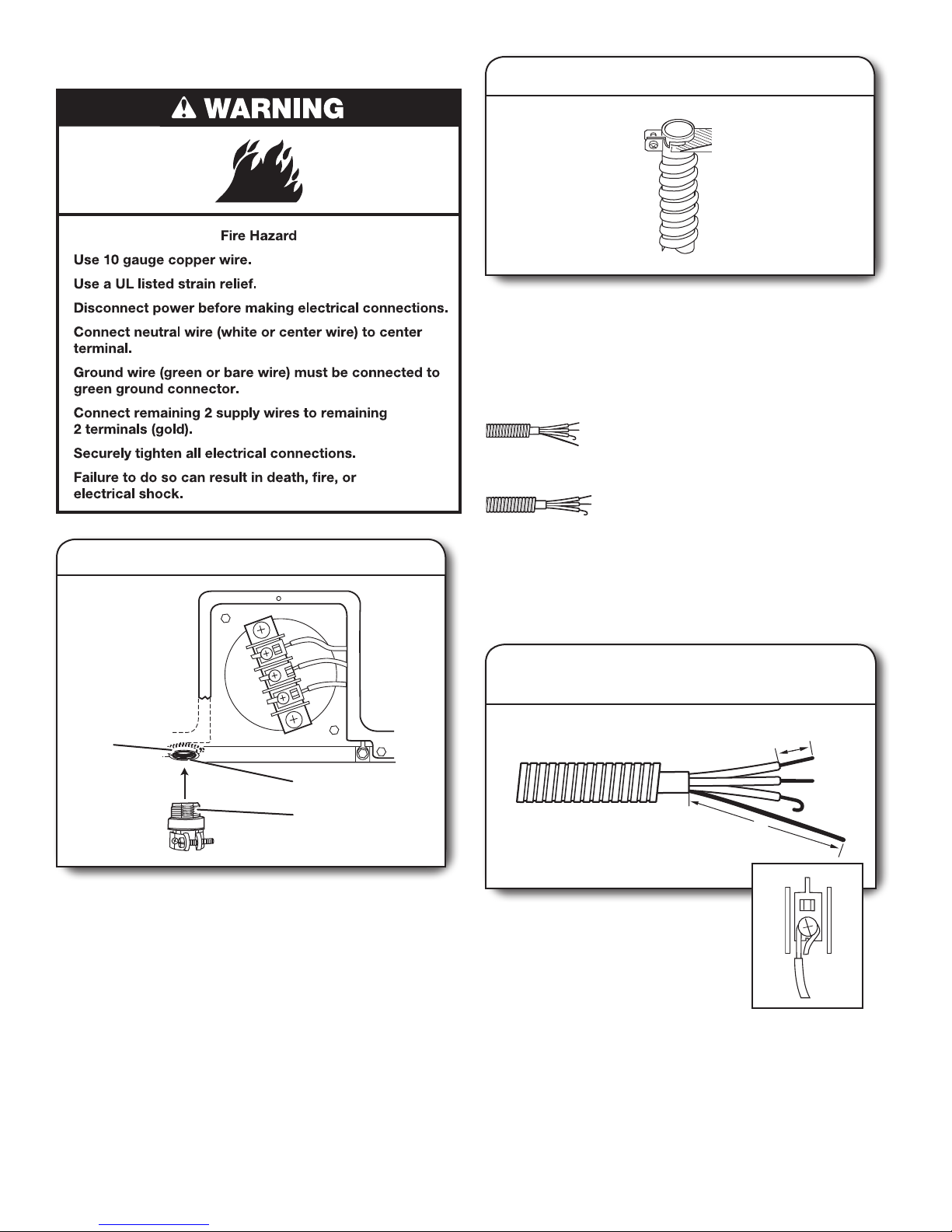
Direct Wire Connection
2. Attach direct wire cable to strain relief
Put direct wire cable through the strain relief. The strain relief
should have a tight t with the dryer cabinet and be in a
horizontal position. Tighten strain relief screw against the
direct wire cable.
If your wiring looks like this:
4-wire direct connection:
Go to “4-wire Direct Wire Connection”
on this page.
3-wire direct connection:
Go to “3-wire Direct Wire Connection”.
1. Attach direct wire strain relief
A
B
C
Unscrew the removable conduit connector and any screws
from a 3/4" (19 mm) UL listed strain relief (UL marking on
strain relief). Put the threaded section of the strain relief
through the hole below the terminal block opening. Reaching
inside the terminal block opening, screw the removable conduit
connector onto the strain relief threads.
A. Removable conduit connector
B. Hole below terminal block opening
C. Strain relief threads
4-wire Direct Wire Connection
IMPORTANT: A 4-wire connection is required for mobile
homes and where local codes do not permit the use of
3-wire connections.
1. Prepare your 4-wire cable
for direct connection
1"
(25 mm)
5"
(127 mm)
Direct wire cable must have 5 ft. (1.52 m)
of extra length so Laundry Center can
be moved if needed.
Strip 5" (127 mm) of outer covering
from end of cable, leaving bare ground
wire at 5" (127 mm). Cut 1-1/2" (38 mm)
from remaining 3 wires. Strip insulation
back 1" (25 mm). Shape ends of wires into a hook shape.
When connecting to the terminal block, place the hooked end
of the wire under the screw of the terminal block (hook facing
right), squeeze hooked end together, and tighten screw. See
example above.
13
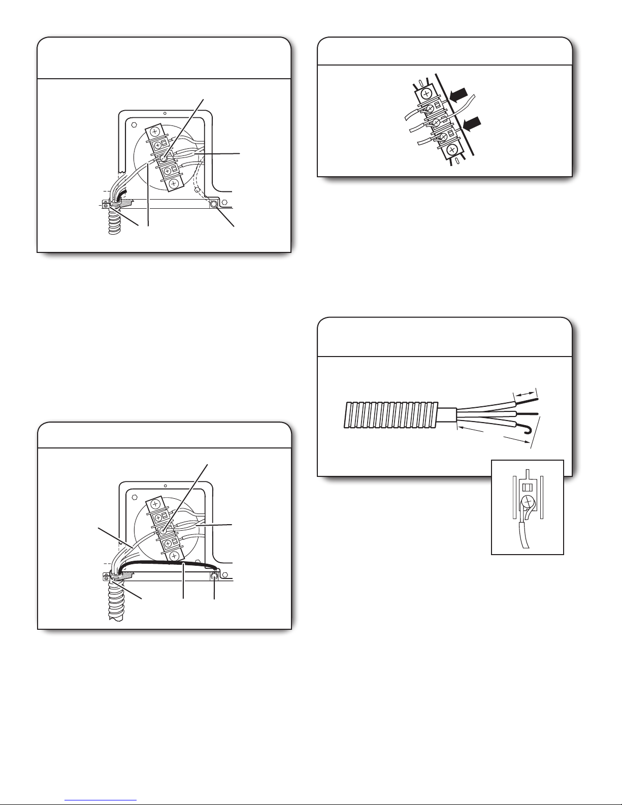
2. Connect neutral ground wire
A
A
B
(89 mm)
and neutral wire
E
D
4. Connect remaining wires
B
Place the hooked ends of the other direct wire cable wires
under the outer terminal block screws (hooks facing right).
Squeeze hooked ends together. Tighten screws. Tighten strain
C
relief screw. Insert tab of terminal block cover into slot of dryer
rear panel. Secure cover with hold-down screw. Now go to
“Venting Requirements”.
Remove center terminal block screw. Remove neutral ground
wire from external ground conductor screw. Connect neutral
ground wire and place the hooked end (hook facing right)
of the neutral wire (white or center wire) of direct wire cable
under the center screw of the terminal block. Squeeze hooked
ends together. Tighten screw.
A. Center terminal block screw
B. Neutral ground wire
C. External ground conductor screw – Dotted
line shows position of NEUTRAL ground
wire before being moved to center terminal
block screw.
D. Neutral wire (white or center wire)
E. 3/4" (19 mm) UL listed strain relief
3. Connect ground wire
C
F
E
D
3-wire Direct Wire Connection
Use where local codes permit connecting cabinet-ground
conductor to neutral wire.
1. Prepare your 3-wire cable
for direct connection
1"
(25 mm)
3½"
Direct wire cable must have 5 ft. (1.52 m)
of extra length so Laundry Center can
be moved if needed.
Strip 3-1/2" (89 mm) of outer covering
from end of cable. Strip insulation back
1" (25 mm). If using 3-wire cable with
ground wire, cut bare wire even with
outer covering. Shape ends of wires into a hook shape.
When connecting to the terminal block, place the hooked end
of the wire under the screw of the terminal block (hook facing
right), squeeze hooked end together, and tighten screw. See
example above.
Connect ground wire (green or bare) of direct wire cable
to external ground conductor screw. Tighten screw.
A. Neutral wire (white or center wire)
B. Center terminal block screw
C. Neutral ground wire
D. External ground conductor screw
E. Ground wire (green or bare) of direct
wire cable
F. 3/4" (19 mm) UL listed strain relief
14
2. Connect neutral wire
B
1. Connect neutral ground wire
and neutral wire
A
C
E
Loosen or remove center terminal block screw. Place the
hooked end of the neutral wire (white or center wire) of direct
wire cable under the center screw of terminal block (hook
facing right). Squeeze hooked end together. Tighten screw.
A. Neutral wire (white or center wire)
B. Center terminal block screw
C. Neutral ground wire
D. External ground conductor screw
E. 3/4" (19 mm) UL listed strain relief
D
3. Connect remaining wires
A
B
C
D
Remove center terminal block screw. Remove neutral ground
wire from external ground conductor screw. Connect neutral
ground wire and the neutral wire (white or center wire) of
power supply cord/cable under center terminal block screw.
Tighten screw.
A. Neutral wire (white or center wire)
B. Neutral ground wire
C. External ground conductor screw – Dotted
line shows position of NEUTRAL ground
wire before being moved to center terminal
block screw.
D. Grounding path determined by a qualified
electrician
Place the hooked ends of the other direct wire cable wires
under the outer terminal block screws (hooks facing right).
Squeeze hooked ends together. Tighten screws. Tighten strain
relief screw. Insert tab of terminal block cover into slot of dryer
rear panel. Secure cover with hold-down screw. Now go to
“Venting Requirements”.
Optional 3-wire Connection
Use for direct wire or power supply cord where local codes
do not permit connecting cabinet-ground conductor to neutral
wire.
2. Connect remaining wires and
connect separate ground wire
Connect the other wires to outer terminal block screws. Tighten
screws. Tighten strain relief screws. Connect a separate copper
ground wire from the external ground conductor screw to an
adequate ground. Insert tab of terminal block cover into slot
of dryer rear panel. Secure cover with hold-down screw. Now
go to “Venting Requirements”.
15
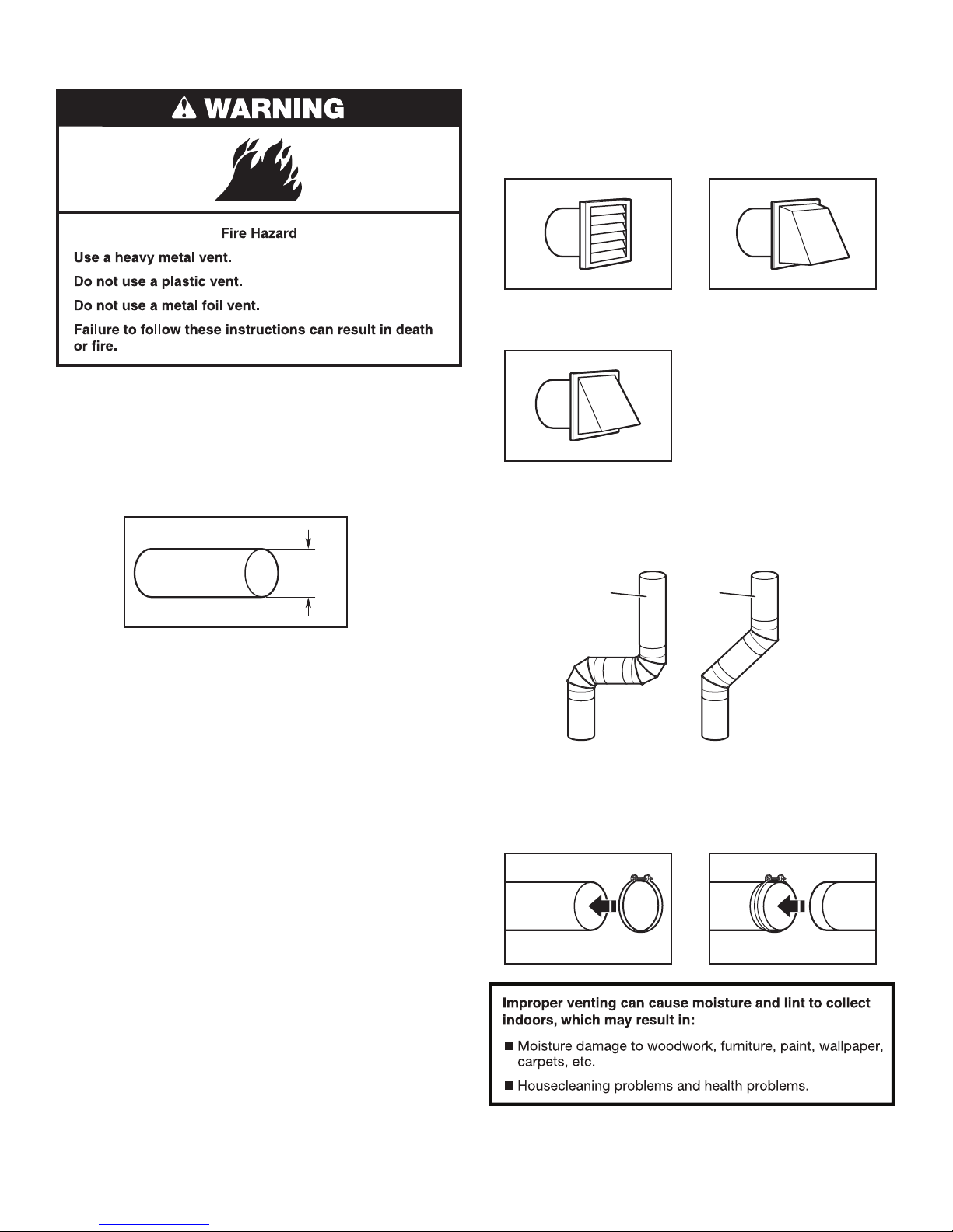
VENTING REQUIREMENTS
Exhaust hoods:
■ Must be at least 12" (305 mm) from ground or any object
that may obstruct exhaust (such as owers, rocks, bushes,
or snow).
■ Do not use an exhaust hood with a magnetic latch.
Recommended Styles:
WARNING: To reduce the risk of re, this Laundry Center
MUST BE EXHAUSTED OUTDOORS.
IMPORTANT: Observe all governing codes and ordinances.
Dryer exhaust must not be connected into any gas vent, chimney,
wall, ceiling, attic, crawlspace, or a concealed space of a
building. Only rigid or exible metal vent shall be used for
exhausting.
4"
(102 mm)
4" (102 mm) heavy metal exhaust vent
■ Only a 4" (102 mm) heavy metal exhaust vent and clamps
may be used. DURASAFE™ venting products are recommended.
■ Do not use plastic or metal foil vent.
Rigid metal vent:
■ Recommended for best drying performance and to avoid
crushing and kinking.
Flexible metal vent: (Acceptable only if accessible to clean)
■ Must be fully extended and supported in nal Laundry
Center location.
■ Remove excess to avoid sagging and kinking that may
result in reduced airow and poor performance.
■ Do not install in enclosed walls, ceilings, or oors.
■ The total length should not exceed 7-3/4 ft. (2.4 m).
■ The length of exible metal vent used must be included in the
overall vent system design as shown in the “Vent System Chart”.
NOTE: If using an existing vent system, clean lint from entire length
of the system and make sure exhaust hood is not plugged with
lint. Replace plastic or metal foil vents with rigid metal or exible
metal vents. Review Vent System Chart and if necessary, modify
existing vent system to achieve best drying performance.
Louvered Hood
Box Hood
Acceptable Style:
Angled Hood
Elbows:
■ 45° elbows provide better airow than 90° elbows.
Recommended Styles:
Good
Better
Clamps:
■ Use clamps to seal all joints.
■ Exhaust vent must not be connected or secured with screws
or other fastening devices that extend into interior of duct
and catch lint. Do not use duct tape.
16
Vent products can be purchased from your dealer. For further
information, please call 1-800-4-MY-HOME® (1-800-469-4663)
or visit our website at www.sears.com or www.sears.ca.
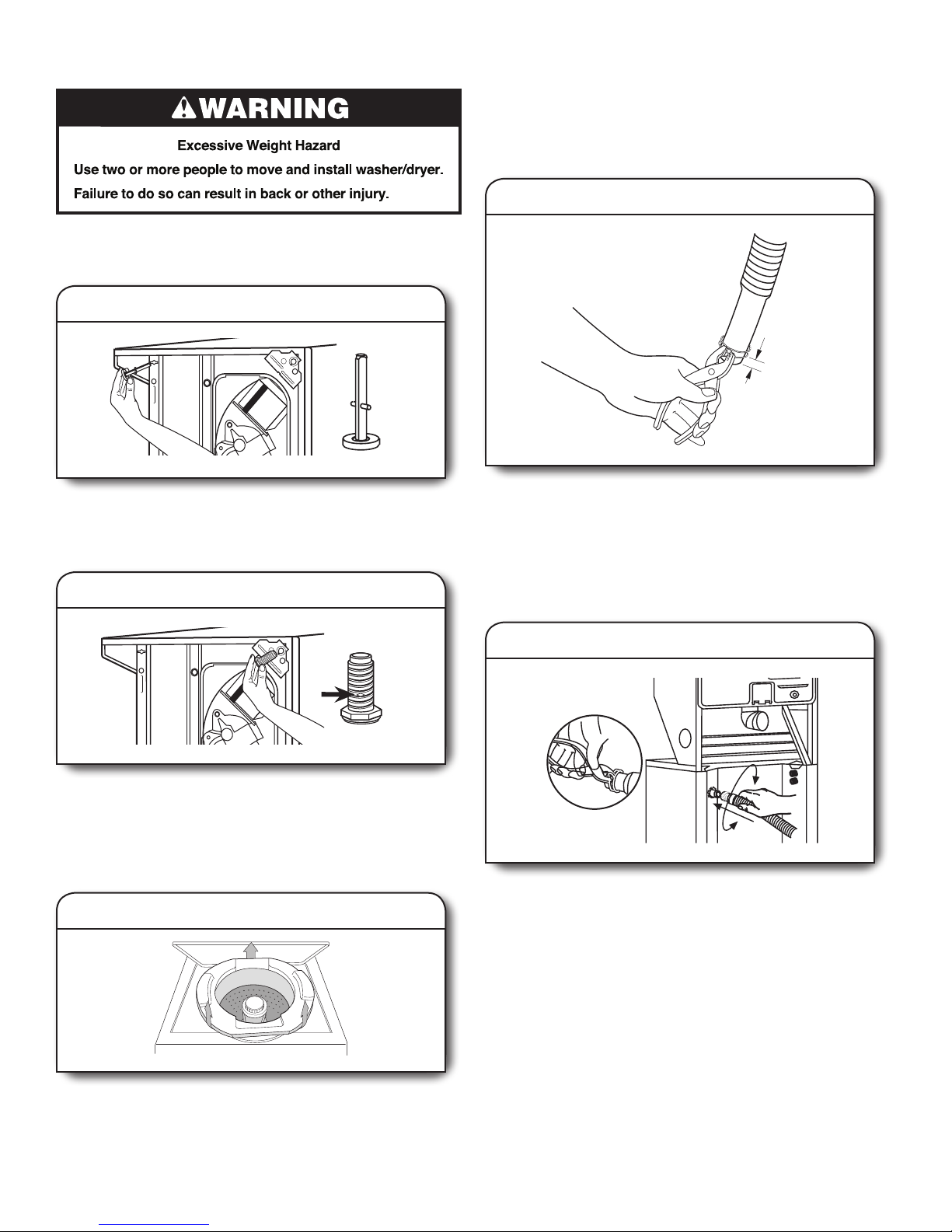
INSTALL LEVELING LEGS
To avoid damaging oor, use a large at piece of cardboard from
shipping carton. Gently place Laundry Center on its side, on the
cardboard.
1. Install rear leveling legs
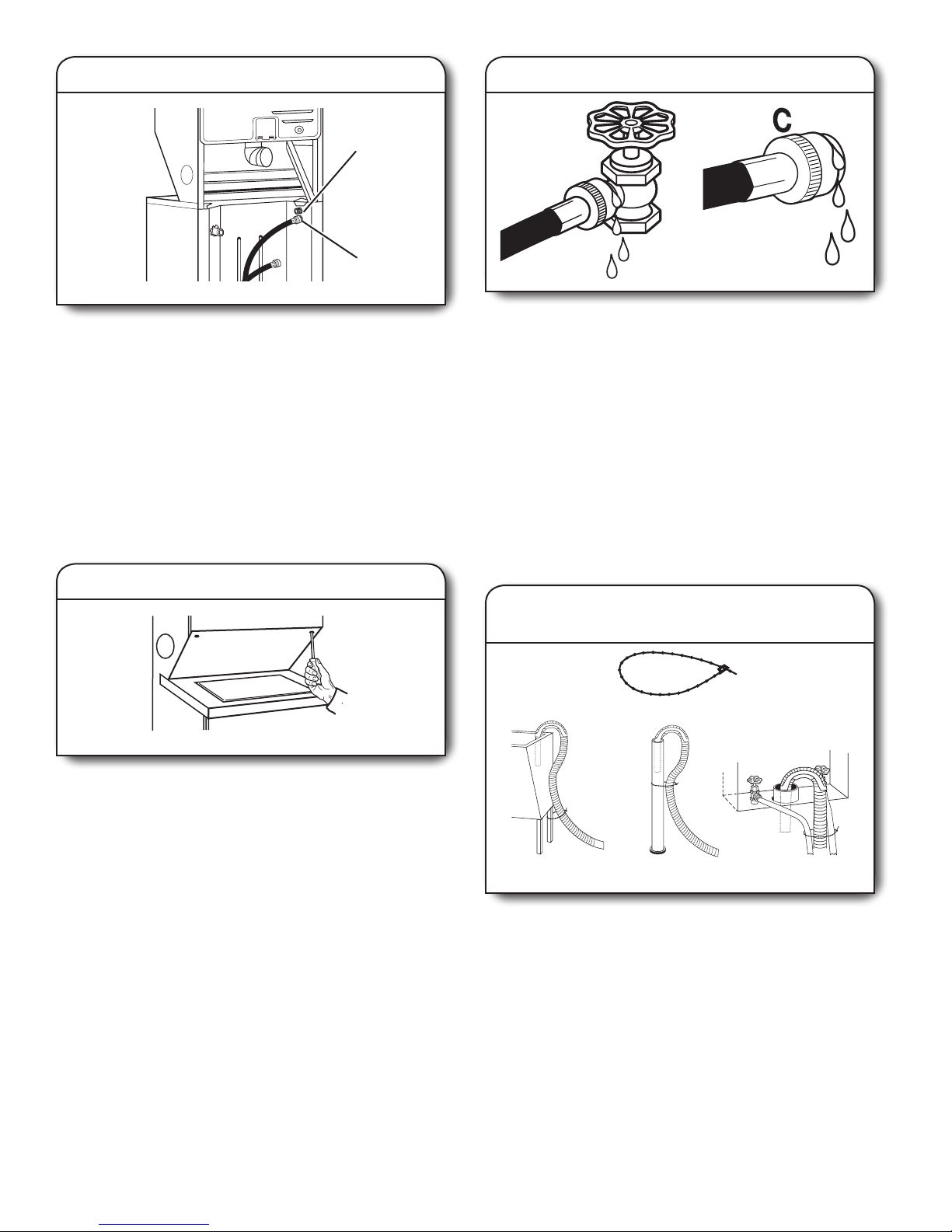
CONNECT DRAIN HOSE
Proper connection of the drain hose avoids damage to your oors
due to water leakage. To keep the drain hose from coming o or
leaking, it must be installed according to the following instructions:
IMPORTANT: To ensure proper installation, this procedure must be
followed exactly.
1. Attach clamp to drain hose
1/4"
(6.4 mm)
Push legs into holes in rear corners until they snap into place.
Check adjustability of rear legs by pushing in one leg. The
other leg should come out. Check both legs. If they do not
move freely, repeat procedure.
2. Install front leveling legs
Examine front leveling legs; find diamond marking. Screw front
legs by hand into holes in triangular braces in front corners.
Use wrench to finish turning the legs until diamond marking is
no longer visible. Gently stand Laundry Center upright.
REMOVE FOAM PACKING
1. Pull foam packing ring out of washer
Check the drain hose to see whether it is the proper length.
Wet the inside of the straight end of the drain hose with
tap water.
IMPORTANT: Do not use any lubricant other than water.
Squeeze the ears of the silver, double-wire clamp with pliers to
open. Place clamp over the straight end of the drain hose 1/4"
(6.4 mm) from the end.
2. Attach drain hose to drain connector
Open clamp. Twist hose back and forth while pushing onto
drain connector on the side of the Laundry Center. Continue
until hose contacts the ribbed stops on the cabinet. Place
clamp over the area marked “CLAMP.” Release clamp.
Open the washer lid. The latch under the dryer will keep
the lid open. Pull the foam packing ring out of the washer.
NOTE: Keep the foam ring and use it when transporting
your Laundry Center. This packing material is used to keep
the washer tub stable during transport.
17
3. Place drain hose in standpipe
or laundry tub
Drain
hose form
4.5"
(114 mm)
2. Connect inlet hoses to water faucets
Make sure drain hose form is in correct position. Place
hose into standpipe (shown) or over side of laundry tub.
IMPORTANT: 4.5" (114 mm) of drain hose should be inside
standpipe; do not force excess hose into standpipe or lay
on bottom of laundry tub. Drain hose form must be used.
For use with floor drain: Do not install the drain hose form
onto the corrugated drain hose. You may need additional
parts. See Floor drain under “Alternate Parts”.
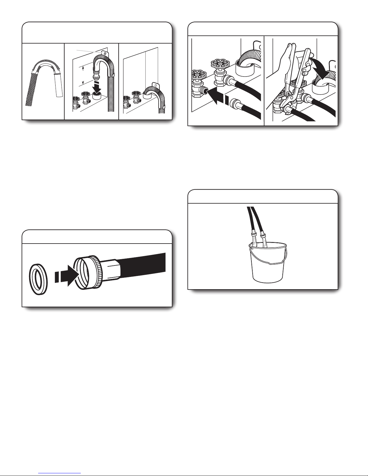
CONNECT INLET HOSES
Laundry Center must be connected to water faucets with new
inlet hoses with at washers (not provided). Do not use old hoses.
NOTE: Both hoses must be attached and have water owing to
inlet valves.
1. Insert washer into each hose
Insert a new flat washer into each end of the inlet hoses (not
provided). Firmly seat the washers in the couplings.
Make sure the washer basket is empty. Attach hose to the hot
water faucet. Screw on coupling by hand until it is seated on
the washer. Attach hose to the cold water faucet. Screw on
coupling by hand until it is seated on the washer. Using pliers,
tighten the couplings with an additional two-thirds turn.
IMPORTANT: Do not overtighten or use tape or sealants
when attaching inlet hoses to faucets or to the Laundry Center.
Damage can result.
3. Clear water lines
Run water through both faucets and inlet hoses, into a
laundry tub, drainpipe, or bucket to get rid of particles in the
water lines that might clog the inlet valve screens. Check the
temperature of the water to make sure that the hot water hose
is connected to the hot water faucet and that the cold water
hose is connected to the cold water faucet.
18
4. Connect inlet hoses to washer
A
B
Attach the hot water hose to the bottom inlet valve. Attaching
the hot water hose first makes it easier to tighten connection
with pliers. Screw on coupling by hand until it is seated on the
washer. Using pliers, tighten the coupling with an additional
two-thirds turn.
Attach the cold water hose to the top inlet valve. Screw on
coupling by hand until it is seated on the washer. Using pliers,
tighten the coupling with an additional two-thirds turn.
IMPORTANT: Do not overtighten or use tape or sealants
when attaching inlet hoses to faucets or to the Laundry Center.
Damage can result.
A. Cold water inlet valve (top)
B. Hot water inlet valve (bottom)
6. Check for leaks
Turn on the water faucets and check for leaks. A small amount
of water might enter the washer. You will drain this later.
NOTE: Replace inlet hoses after 5 years of use to reduce the
risk of hose failure. Record hose installation or replacement
dates for future reference.
If you connect only one water hose, you must cap off the
remaining water inlet port.
Periodically inspect and replace hoses if bulges, kinks, cuts,
wear, or leaks are found.
The Laundry Center must be connected to the water faucets
using the new hoses. Do not use old hoses.
SECURE DRAIN HOSE
Move Laundry Center to its nal location and remove any
cardboard used to move Laundry Center.
5. Move laundry center to nal location
If you are working in a closet or recessed area, move the
Laundry Center into its final location and remove cardboard
from under the Laundry Center. Remove the access panel by
removing 2 Phillips-head screws located at the top of the
access panel. Set panel and screws aside. Complete hookup
of water hoses through the access area. Replace access panel
upon completion of Laundry Center installation.
1. Wrap the drain hose to laundry tub leg
or standpipe
A
B C D
Locate removable tie strap (A) included in parts package.
Wrap the drain hose to the laundry tub leg (B) or standpipe (C)
with the removable tie strap and secure. If the water faucets
and the drain standpipe are recessed, put the hooked end of
the drain hose in the standpipe. Tightly wrap the removable tie
strap around the water inlet hoses and the drain hose (D).
19
PLAN VENT SYSTEM
D
E
F
G
H
Recommended exhaust installations
Typical installations vent the dryer from the rear of the Laundry
Center. Other installations are possible.
A
B
C
A. Dryer E. Elbow
B. Rigid metal or flexible metal vent F. Clamps
C. Clamps G. Elbow
D. Wall H. Exhaust hood
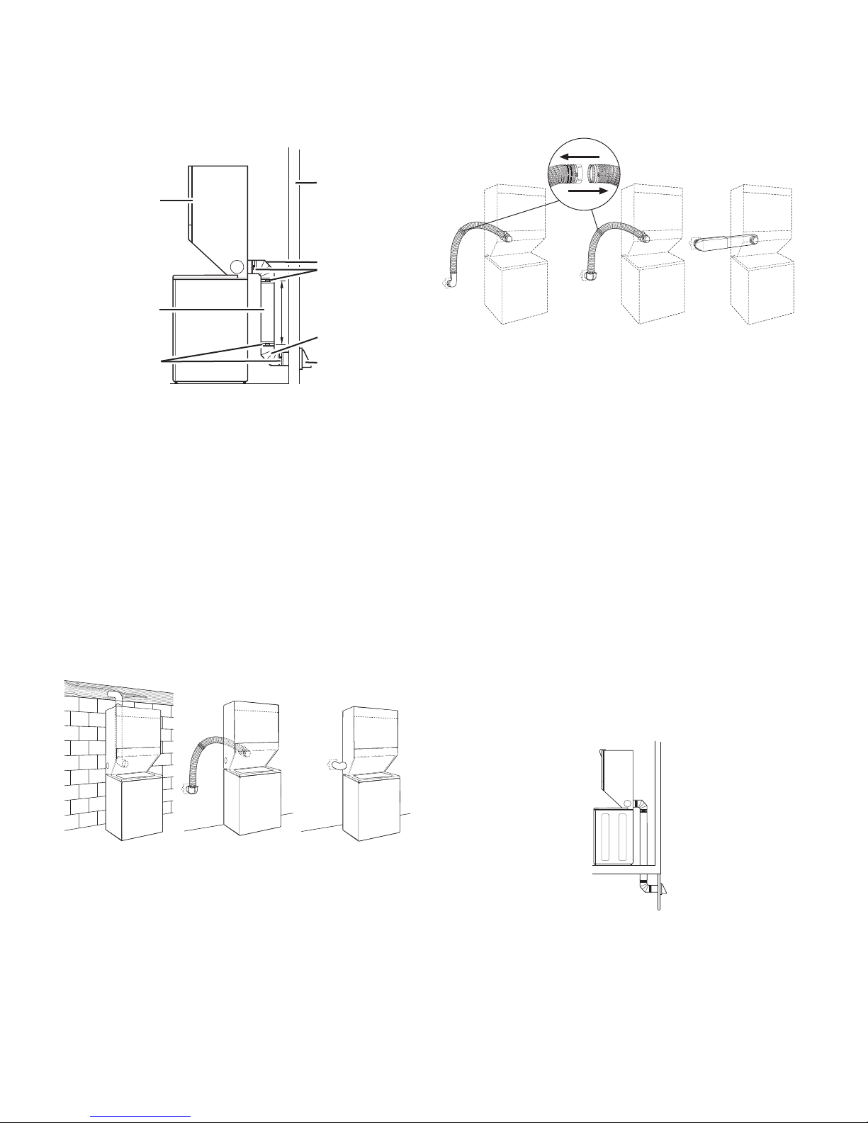
Optional exhaust installations
This Laundry Center can be converted to exhaust out the right or
left side. To convert the Laundry Center, use Side Exhaust Kit Part
Number 279823. If your Laundry Center was previously exhausted
from the right or left side, it can be converted to rear exhaust by
using standard oset connections. To cover the hole in the side,
one of the following plugs can be added:
692790 (white)
3979370 (graphite)
3977784 (biscuit)
Follow the instructions in the kit to install. Kits are available from
your local Sears store or Sears Service Center.
Alternate installations for close clearances
Venting systems come in many varieties. Select the type best
for your installation. Three close-clearance installations are shown.
Refer to the manufacturer’s instructions provided with the vent
system.
A B C
A. Loop system with standard elbows
B. Loop system with one offset and one standard elbow
C. Vent system with one periscope (2" [51 mm] clearance)
NOTE: The following kits for close clearance alternate
installations are available for purchase. To order, please call
1-800-4-MY-HOME® (1-800-469-4663).
Over-the-Top Installation: Part Number 26-49900
Periscope Installation Part Number 26-49901 –
(For use with dryer vent Less than 5" (127 mm)
to wall vent mismatch): mismatch
Part Number 26-49908 –
5" (127 mm) to 18" (457 mm)
mismatch
Part Number 26-49904 –
18" (457 mm) to 29" (737 mm)
mismatch
Part Number 26-49905 –
29" (737 mm) to 50" (1.27 m)
mismatch
Special provisions for mobile home installations
The exhaust vent must be securely fastened to a noncombustible
portion of the mobile home structure and must not terminate
beneath the mobile home. Terminate the exhaust vent outside.
A B C
A. Standard rear offset exhaust installation
B. Rear exhaust for offset close clearance connection
C. Left or right side exhaust installation
20
Determine vent path
■ Select the route that will provide the straightest and most
direct path outdoors.
■ Plan the installation to use the fewest number of elbows
and turns.
■ When using elbows or making turns, allow as much room
as possible.
■ Bend vent gradually to avoid kinking.
■ Use the fewest 90° turns possible.
Determine vent length and elbows needed
for best drying performance
■ Use the Vent system chart below to determine the type of vent
material and hood combinations acceptable to use.
NOTE: Do not use vent runs longer than those specified in the
Vent system chart. Exhaust systems longer than those specified
will:
■ Shorten the life of the dryer.
■ Reduce performance, resulting in longer drying times and
increased energy usage.
The Vent system chart provides venting requirements that will
help to achieve the best drying performance.
Vent System Chart
NOTE: Side exhaust installations add a 90° turn inside the
Laundry Center. To determine maximum exhaust length, add
one 90° turn to the chart.
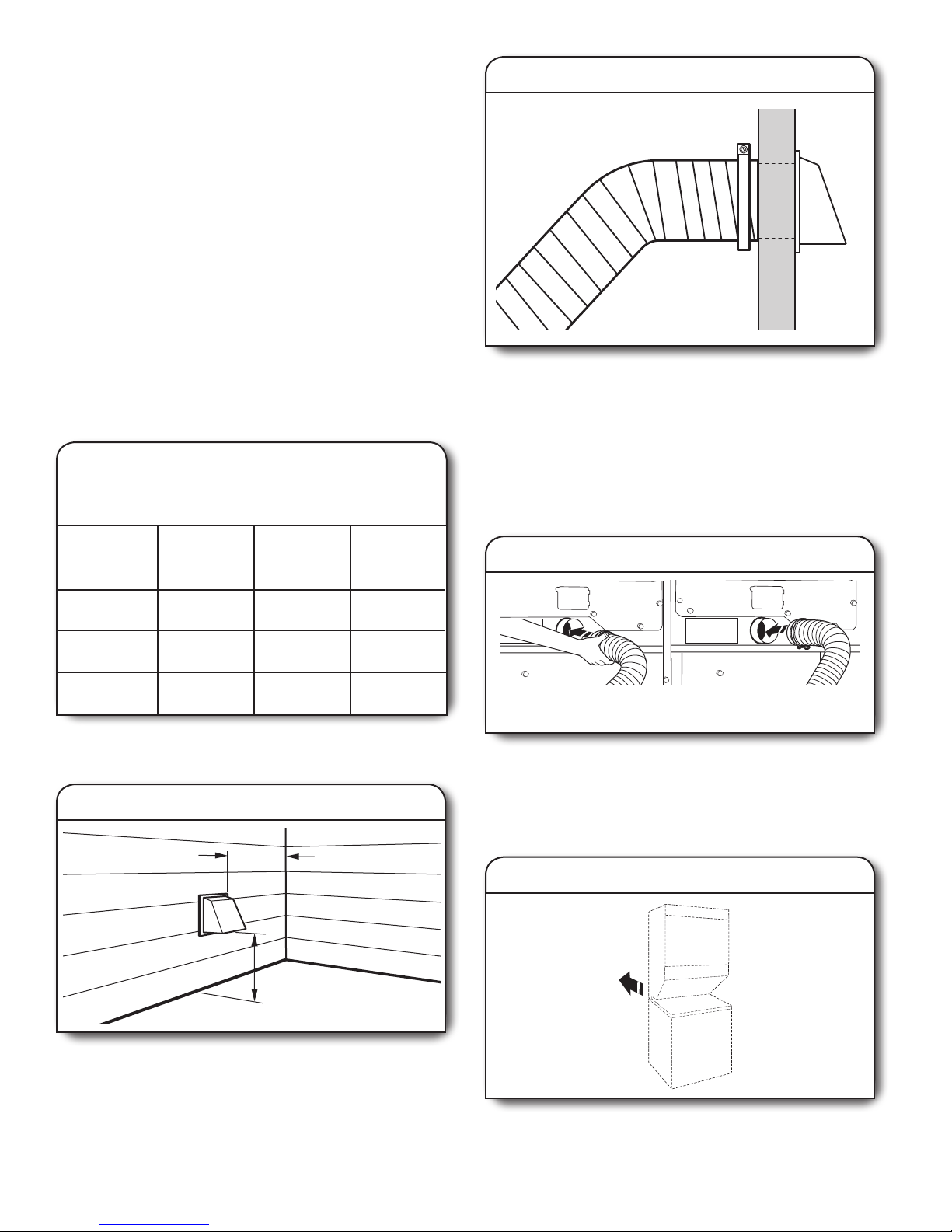
2. Connect vent to exhaust hood
Vent must t inside the exhaust hood. Secure vent to exhaust
hood with 4" (102 mm) clamp. Run vent to dryer location using
straightest path possible. See “Determine vent path” in “Plan
Vent System”. Avoid 90° turns. Use clamps to seal all joints.
Do not use duct tape, screws, or other fastening devices that
extend into interior of vent to secure vent, because they can
catch lint.
CONNECT VENT
Number
of 90° turns
or elbows
Type
of vent
0 Rigid metal
1
2
Rigid metal
Rigid metal
INSTALL VENT SYSTEM
1. Install exhaust hood
Box or
louvered
hoods
43 ft. (13.1 m)
33 ft. (10.1 m)
23 ft. (7.0 m)
12" min.
(305 mm)
12" min.
(305 mm)
Angled
hoods
36 ft. (11.0 m)
26 ft. (7.9 m)
16 ft. (4.9 m)
1. Connect vent to exhaust outlet
Connecting from front
(for closet or recessed area)
Using a 4" (102 mm) clamp, connect vent to exhaust outlet in
Laundry Center. If connecting to existing vent, make sure the
vent is clean. Dryer vent must t over dryer exhaust outlet and
inside exhaust hood. Check that vent is secured to exhaust
hood with a 4" (102 mm) clamp.
Connecting
from rear
2. Move Laundry Center to nal location
Install exhaust hood and use caulking compound to seal
exterior wall opening around exhaust hood.
Move Laundry Center to its nal location. Avoid crushing or
kinking vent.
21
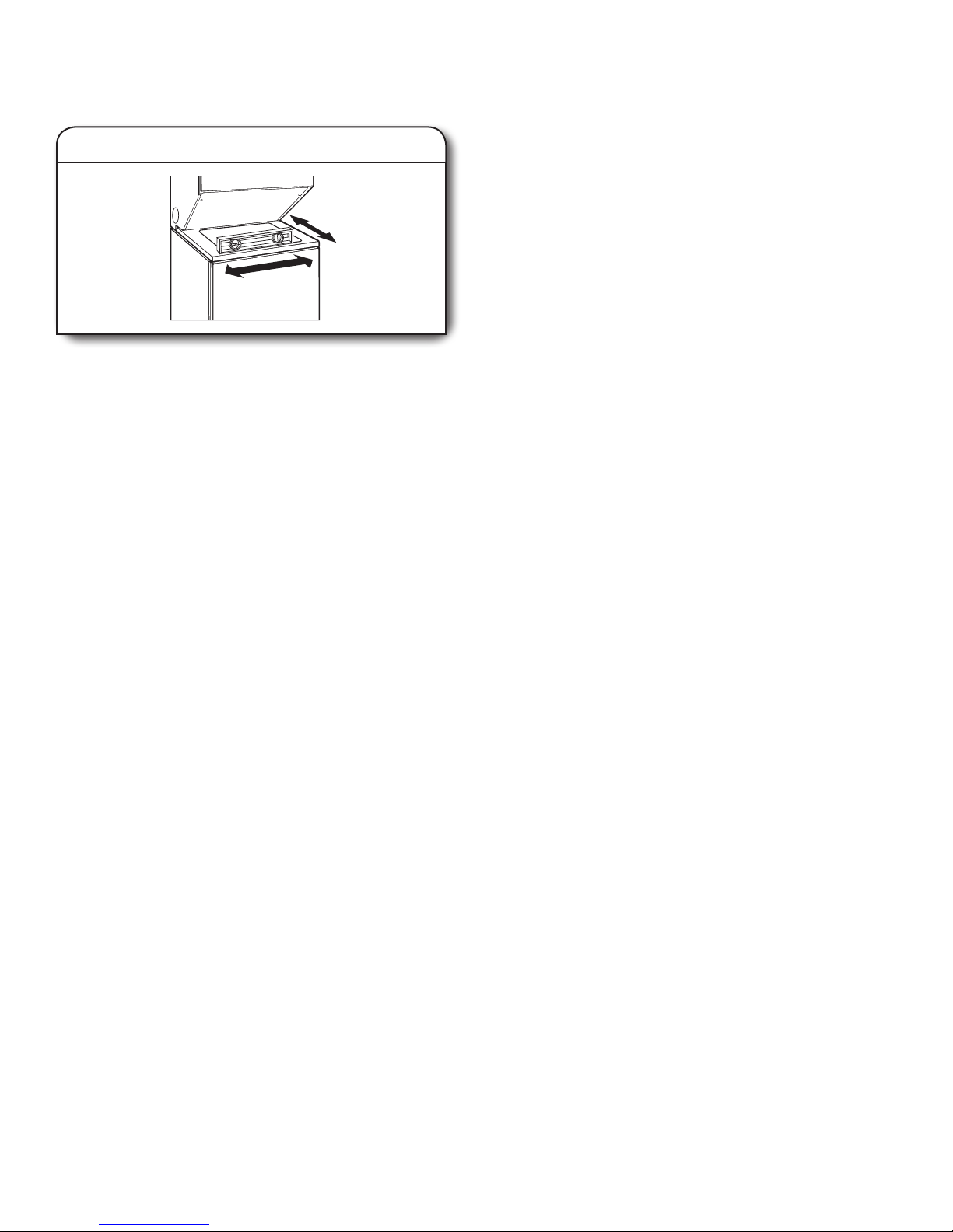
LEVEL LAUNDRY CENTER
Properly leveling your Laundry Center avoids excessive noise
and vibration.
1. Check levelness of laundry center
Check levelness of Laundry Center by placing a level on the
top edge of washer, rst side to side, then front to back. If
Laundry Center is not level, prop up front with a wood block
and adjust feet up or down as necessary. Remove wood block
and lower Laundry Center. Repeat this step until Laundry
Center is level.
COMPLETE INSTALLATION
■ Check that all parts are now installed. If there is an extra
part, go back through the steps to see what was skipped.
■ Check that you have all of your tools.
■ Dispose of/recycle all packaging materials. Keep the plastic
foam for use if Laundry Center should be transported.
■ Check Laundry Center’s nal location. Be sure vent is not
crushed or kinked.
■ Check that Laundry Center is level and front leveling feet
are tight. See “Level Laundry Center.”
■ On 240 volt models, for power supply cord installation,
plug into an outlet. For direct wire installation (U.S. only),
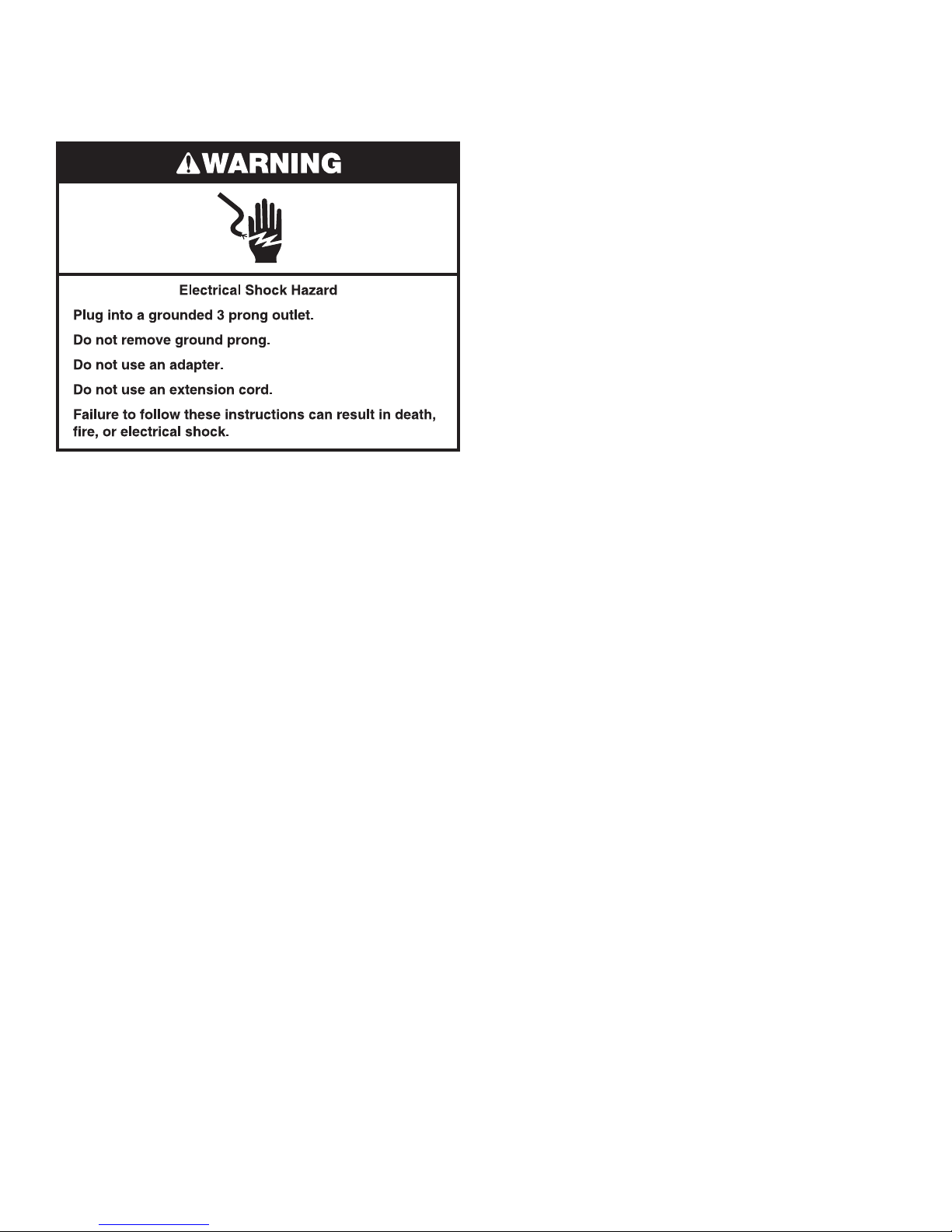
turn on power. On 120 volt models, plug into a grounded
3 prong outlet.
■ Check that the water faucets are on.
■ Check for leaks around faucets and inlet hoses.
■ Remove lm on the console and any tape remaining
on Laundry Center.
■ Read “Washer Use” and “Dryer Use.”
■ Wipe dryer drum interior thoroughly with a damp cloth
to remove any dust.
■ To test the washer, measure 1/2 the normal recommended
amount of detergent and pour it into the washer. Close the lid.
Select HEAVY DUTY and pull out the CYCLE CONTROL knob.
Allow the washer to complete one whole cycle.
■ To test the dryer, set the dryer on a full heat cycle
(not an air cycle) for 20 minutes and start the dryer.
If the dryer will not start, check the following:
• Controls are set in a running or “On” position.
• PUSH TO START DRYER button has been rmly pushed.
• On 240 volt models, Laundry Center is plugged into an
outlet and/or electrical supply is on. On 120 volt models,
Laundry Center is plugged into a grounded 3 prong outlet
and/or electrical supply is on.
• Household fuse is intact and tight, or circuit breaker
has not tripped.
• Dryer door is closed.
■ When the dryer has been running for 5 minutes, open the dryer
door and feel for heat. If you feel heat, cancel cycle and close
the door.
If you do not feel heat, turn the dryer o and check
the following:
• Controls are set on a heated cycle, not an air cycle.
• On 240 volt models, there may be 2 household fuses or
circuit breakers for the dryer. Check that both fuses are
intact and tight, or that both circuit breakers have not
tripped. If there is still no heat, contact a qualied
technician.
NOTE: You may notice an odor when dryer is rst heated. This
odor is common when the heating element is rst used. The odor
will go away.
22
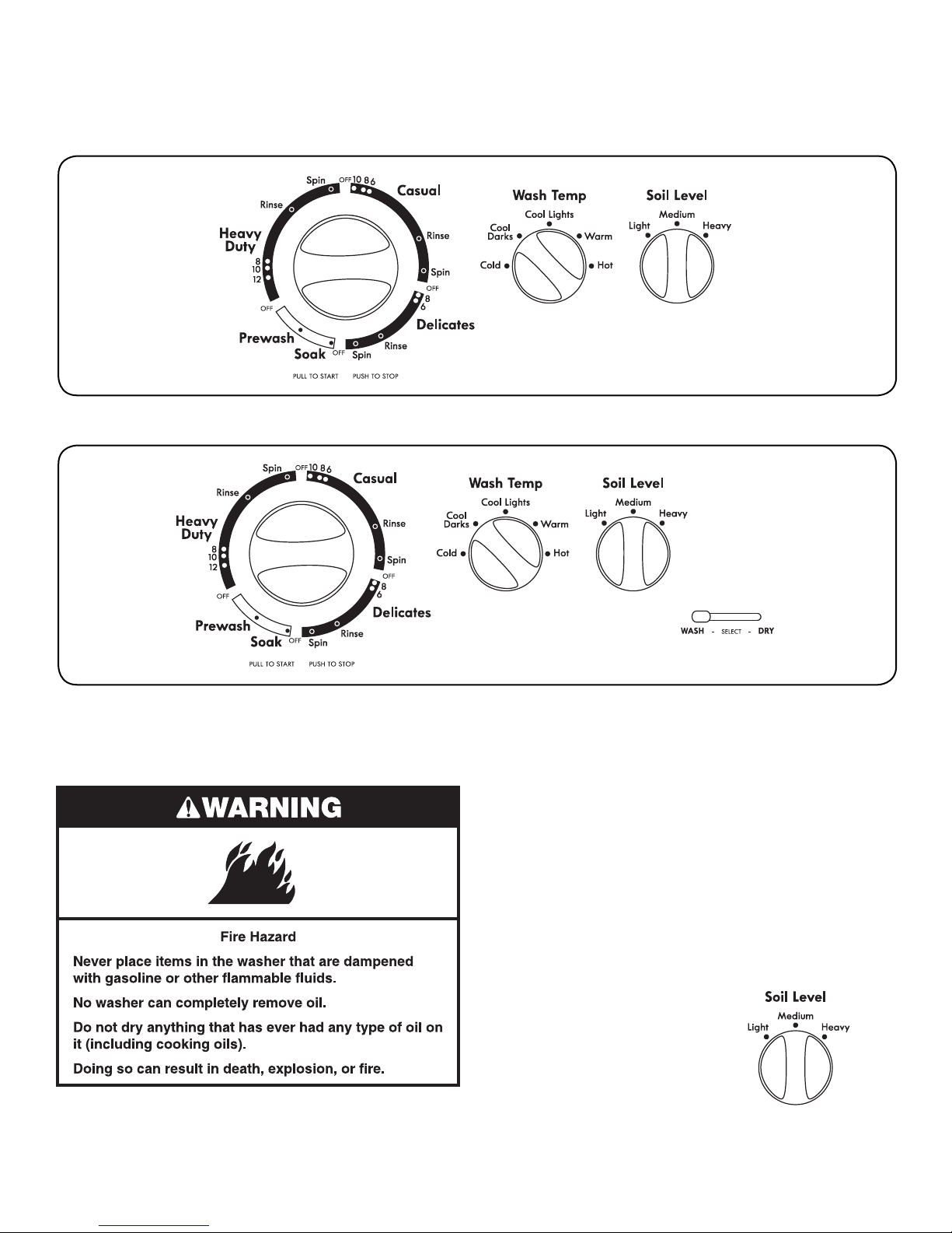
CONTROL PANEL AND FEATURES
240 Volt Models
120 Volt Models
WASHER USE
Not all features and options are available on all models.
Appearance may vary.
STARTING YOUR WASHER
WARNING: To reduce the risk of fire, electric shock, or injury to
persons, read the IMPORTANT SAFETY INSTRUCTIONS before
operating this washer.
The following is a guide to starting your washer. Periodic
references to other sections of this manual provide more detailed
information.
■ Add a measured amount of detergent or single-dose laundry
packet into the basket before adding clothes. If using Oxi-type
boosters, color-safe bleach, or fabric softener crystals, add to
the bottom of the washer basket as well.
■ Place a load of sorted clothes in the washer.
• Load evenly to maintain washer balance. Mix large and
small items. See “Loading”.
• Tightly packed loads may cause poor cleaning.
■ Close the washer lid.
■ Turn the SOIL LEVEL selector knob
to the correct setting for your wash
load and the type of fabric
being washed.
23
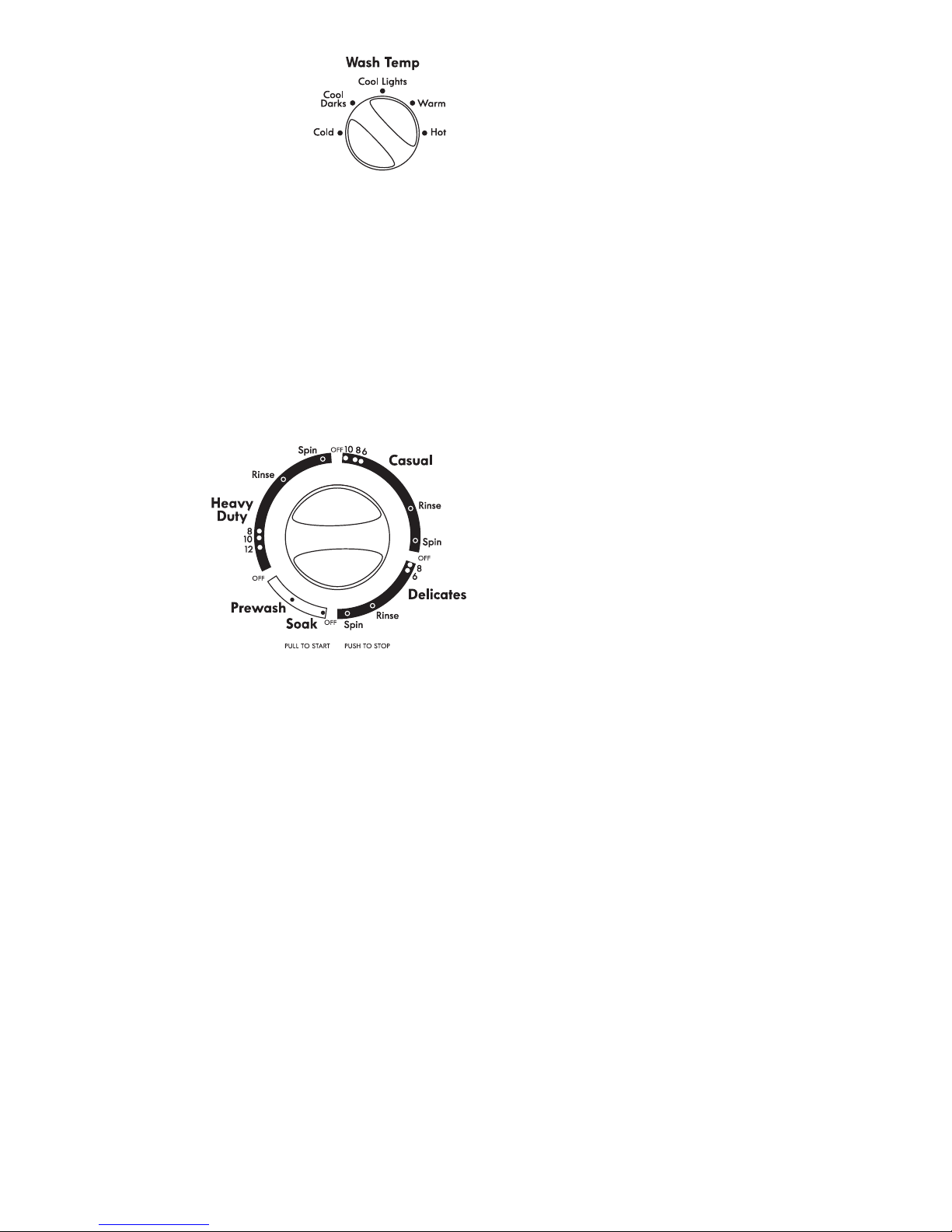
■ Set the WASH TEMP selector
to the correct setting for the type
of fabric and soils being washed.
Use the warmest water safe for
the fabric. Follow garment label
instructions. All rinses are cold
rinses.
Wash Temp Use For
Hot Whites and pastels; Heavy soils
Warm Bright colors; Moderate to light soils
Cool Colors that bleed or fade; Light soils
Cold Colors that bleed or fade; Light soils
■ Push in the CYCLE CONTROL knob and turn it clockwise
to the wash cycle you want. Pull out the CYCLE CONTROL
knob to start the washer.
To stop or restart your washer:
■ To stop the washer at any time, push in the CYCLE CONTROL
knob.
■ To restart the washer, close the lid (if open) and pull out the
CYCLE CONTROL knob.
CYCLES
This section describes the available
wash cycles and will help you
make the best cycle
selections for your
wash loads. Each
cycle is designed
for dierent types
of fabric and soil levels.
■ The washer pauses
briey throughout
each cycle. These
pauses are normal.
Refer to “Normal Sounds”
for sounds you may
hear during a wash cycle.
■ Refer to “Understanding Washer Cycles” to learn what happens
during a wash cycle.
Soak
The Soak cycle features 4 minutes of agitation followed by an
unlimited soak time to help remove heavy soils and stains that
need pretreatment. You will need to reset the washer to a Spin
setting to remove water.
■ The Soak cycle should be followed by the Heavy Duty,
Casual, or Prewash cycle with additional detergent.
NOTE: Hot water is not recommended for soaking. It may set
some stains.
Prewash
Use this cycle to get up to 4 minutes of agitation to help remove
heavy soils and stains that need pretreatment.
■ The Prewash cycle should be followed by the Heavy Duty or
Casual cycle with additional detergent.
RINSE AND SPIN
When using extra detergent for heavily soiled clothes, or when
washing special-care items, you may nd an extra rinse and spin
is needed.
■ Push in the CYCLE CONTROL knob and turn it clockwise to any
of the RInse settings.
• For fast agitation and spin, use the Heavy Duty cycle.
• For slow agitation and spin, use the Casual cycle.
■ Set SOIL LEVEL and WASH TEMP controls to the desired
setting.
■ Pull out the CYCLE CONTROL knob. The washer automatically
lls to the correct load size, agitates, drains, and spins.
DRAIN AND SPIN
A drain and spin may help shorten drying times for some heavy
fabrics or special-care items by removing excess water.
■ Push in the CYCLE CONTROL knob and turn it clockwise
to any of the Spin settings.
• For a fast spin, use the Heavy Duty cycle.
• For a slow spin, use the Casual cycle.
■ Pull out the CYCLE CONTROL knob. The washer drains,
then spins.
Heavy Duty
Use this cycle for sturdy or heavily soiled loads. The wash
combines fast-speed agitation and fast spin speed.
■ Select cycle agitation time (8, 10, or 12 minutes); choose more
time for heavily soiled, sturdy fabrics and less time for lightly
soiled, sturdy fabrics.
Casual
The Casual cycle includes a load-cooling process that reduces
wrinkling. The wash combines fast- and slow-speed agitation and
slow spin speed.
Part way through the cycle, the washer will pause for
approximately 2 minutes while some of the wash water is drained
and replaced with rinse water.
Delicates
Use this cycle for lingerie and loosely knit items. Part way through
the cycle, the washer pauses and soaks the load for gentler care
of lightly soiled delicate items. The wash combines slow speed
agitation for gentle soil removal and slow spin speed to reduce
wrinkling.
24
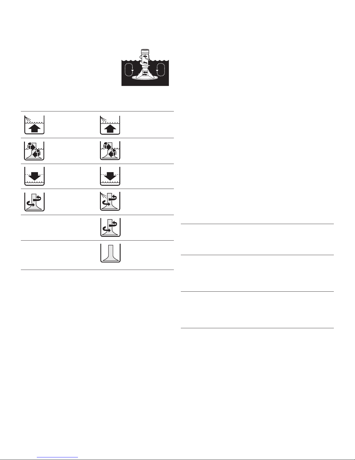
UNDERSTANDING WASHER CYCLES
When the Cycle Control knob is set to a cycle and pulled out,
the washer lls before agitation and timing start. The washer
begins agitating immediately after lling; agitation occurs
with the washer lid down.
During agitation, the agitator creates
a continuous rollover action that provides
a thorough cleaning of the wash load.
After agitation starts, the Cycle Control
knob turns clockwise until it points to an
O area and the cycle ends.
NOTE: The washer pauses briey throughout each cycle. These
pauses are normal for washer operation.
Wash Rinse
1. Fill 1. Fill
2. Wash 2. Rinse
selected
time
3. Drain* 3. Drain
No agitation No agitation
4. Spin 4. Spin-Spray
Rinse
5. Spin
* The Casual cycle partially 6. O
drains, lls, agitates briey,
and drains
NORMAL SOUNDS
As with any new product, you will hear sounds that you are not
accustomed to. You may hear various sounds occurring during
the washing, rinsing, and spinning process. Between changes in
wash actions, there will be momentary pauses. You will hear water
spraying and splashing during the wash and rinse cycles. You may
hear air being pulled through the pump during the end of draining
or gears changing when the cycle changes. These sounds are part
of normal washer operation.
LAUNDRY TIPS
Preparing clothes for washing
Follow these recommendations to help you prolong the life
of your garments.
■ Close zippers, snaps, and hooks to avoid snagging other
items. Remove pins, buckles, and other hard objects to avoid
scratching the washer interior. Remove non-washable trim
and ornaments.
■ Empty pockets and turn them inside out.
■ Turn down cus, brush away lint and dirt.
■ Turn synthetic knits inside out to avoid pilling.
■ Tie strings and sashes so they will not tangle.
■ Mend tears, loose hems, and seams.
■ Treat spots and stains.
■ Stained or wet garments should be washed promptly
for best results.
Sorting
■ Separate heavily soiled items from lightly soiled ones, even
if they would normally be washed together. Separate lint
givers (towels, chenille) from lint takers (corduroy, synthetics,
permanent press). When possible, turn lint givers inside out.
■ Separate dark colors from light colors, colorfast items from non
colorfast items.
■ Sort by fabric and construction (sturdy cottons, knits, delicate
items).
LOADING
Loading suggestions (maximum size loads)
Laundry Center
Heavy Work Clothes Towels
2 pair pants 9 bath towels or
3 work shirts 6 bath towels,
3 hand towels &
6 washcloths
Casual Mixed Load
6 shirts or 1 pair pants
2 double sheets & 2 pillowcases
2 pillowcases or 2 shirts
2 single sheets & 1 T-shirt
2 pillowcases
Knits Delicates
2 pair pants & 2 shirts or 1 camisole
3 dresses 2 slips
4 undergarments
1 set of sleepwear
1 half slip
25
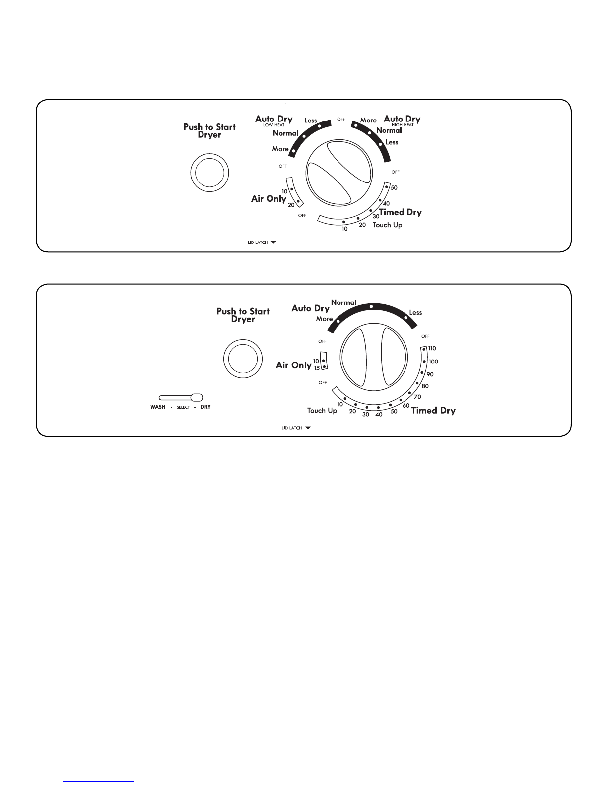
CONTROL PANEL AND FEATURES
240 Volt Models
120 Volt Models
DRYER USE
Not all features and options are available on all models.
Appearance may vary.
26
STARTING YOUR DRYER
WARNING: To reduce the risk of fire, electric shock, or injury to
persons, read the IMPORTANT SAFETY INSTRUCTIONS before
operating this appliance.
Before using your dryer, wipe the dryer drum with a damp cloth
to remove dust from storing and shipping.
■ Clean lint screen before each load.
See “Cleaning the Lint Screen”.
■ Load clothes loosely into the dryer and
close the door. Do not pack the dryer.
Allow space for clothes to tumble freely.
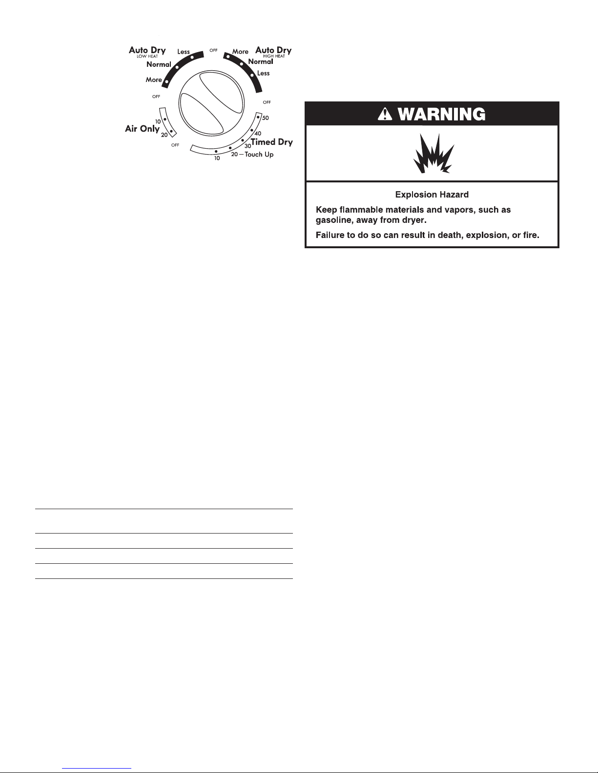
■ Turn the CYCLE CONTROL knob to the
recommended cycle and temperature
for the type of load being dried. See
“Drying, Cycle, and Temperature Tips.”
■ On 120 volt models, slide WASH/DRY
selector to DRY.
■ Press the PUSH TO START DRYER knob.
STOPPING AND RESTARTING
You can stop your dryer anytime during a cycle.
To stop your dryer
Open the dryer door or turn the CYCLE CONTROL knob to O.
NOTE: The Cycle Control knob should point to an O area when
the dryer is not in use.
To restart your dryer
■ Close the door.
■ Select a new cycle and temperature (if desired).
■ Press the PUSH TO START DRYER knob.
DRYING, CYCLE, AND TEMPERATURE TIPS
Select the correct cycle and temperature for your load.
Drying tips
■ Follow care label directions when they are available.
■ If you use fabric softener sheets, use only those labeled
as dryer safe. Follow package instructions.
■ Remove the load from the dryer as soon as tumbling stops
to reduce wrinkling. This is especially important for permanent
press, knits, and synthetic fabrics.
Cycle and temperature tips
■ Dry most loads using the Auto Dry Normal setting.
■ Use the More setting for drying heavyweight items such
as towels and work clothes.
■ Use an Auto Dry Normal setting for drying medium weight
items such as sheets, underwear, permanent press fabrics,
and some knits.
■ Use the Less setting for drying lightweight items such as
lingerie, blouses, dresses, and some knits.
■ Use Air Only setting for rubber, plastic, or heat-sensitive
fabrics.
■ Line dry bonded or laminated fabrics.
If you are unsure of the temperature to select for a load, select a
lower setting rather than a higher setting.
NOTE: If you have questions about drying temperatures for various
loads, refer to the care label directions.
LOADING
Load clothes loosely into the dryer. Do not pack the dryer. Allow
space for clothes to tumble freely. The following chart shows
examples of balanced loads that would allow for proper tumbling.
Heavy work 2 pair pants, 3 work shirts
clothes
Delicates 1 camisole, 2 slips, 4 undergarments,
1 set of sleep wear, 1 half slip
Towels 9 bath towels or 6 bath towels,
3 hand towels, 6 washcloths
Mixed Load 2 pillowcases, 1 T-shirt, 2 shirts,
1 pair pants
Knits 2 pants, 2 shirts; or 3 dresses
Permanent 6 shirts; or 2 double sheets & 2 pillowcases;
Press or 2 single sheets & 2 pillowcases
27
CYCLES
Auto Dry
Use this cycle to dry
most loads. Dryness is
determined by thermostats
that react to the temperature
or amount of moisture
in the air exhausted
from the dryer.
This cycle includes a
5 minute (approximate)
cool down period at the end
of the cycle to make clothes
easier to handle and to reduce
wrinkling.
Use Auto Dry Normal cycle to dry most heavy- to medium-weight
fabrics. When the cycle ends, check the dryness of the load.
■ If the load is drier than you like, select a setting closer to LESS
the next time you dry a similar load.
■ If the load is not as dry as you like, complete drying using the
Timed Dry cycle. The next time you dry a similar load, select
a setting closer to MORE.
NOTE: Drying time with an automatic cycle varies according
to the type of fabric, size of load, and temperature setting.
See “Drying, Cycle, and Temperature Tips”.
Timed Dry
Use this cycle to complete drying if items are still damp after
the Auto Dry cycle. Timed Dry is also useful for heavyweight
and bulky items, such as bedspreads, work clothes, and large
loads that require a long drying time. Use this cycle to get up
to 50 minutes of heated drying time on 240 volt models, or
up to 110 minutes of heated drying time on 120 volt models.
The heating cycle is followed by a 5 minute (approximately)
cool down period.
Touch Up
Use this cycle to smooth already dry synthetic and permanent
press clothes that are clean but wrinkled from being crowded in a
closet or suitcase. This setting provides approximately 20 minutes
of heated tumbling followed by a 5 minute (approximately) cool
down period. Remove clothes immediately when tumbling stops.
Air Only
Use the Air Only cycle for items that require drying without heat
such as rubber, plastic, and heat-sensitive fabrics. This chart shows
examples of items that can be dried using an air cycle.
Type of Load Minutes*
Foam rubber – pillows, padded bras, 20–30
stued toys
Plastic items – shower curtains, tablecloths 20–30
Rubber-backed rugs 40–50
Olen, polypropylene, sheer nylon 10–20
*Reset time as needed to allow items to completely dry.
When using Air Only
■ Check that coverings are securely stitched.
■ Shake and u pillows by hand periodically during the cycle.
■ Dry items completely. Foam rubber pillows are slow to dry.
End of Cycle Signal
Your dryer sounds a signal when a drying cycle is nished.
This signal is helpful when you are drying items that need to be
removed as soon as the dryer stops in order to help keep wrinkles
from forming.
240 volt model shown
LAUNDRY CENTER CARE
CLEANING THE LAUNDRY CENTER LOCATION
Keep the Laundry Center area clear and free from items that
would obstruct the ow of combustion and ventilation air.
CLEANING YOUR WASHER
Cleaning the exterior
Use a soft, damp cloth or sponge to wipe up any spills such as
detergent or bleach. Occasionally wipe the outside of your washer
to keep it looking new.
Cleaning the interior
Keep your washer as clean and fresh as your clothes. To keep
washer interior odor-free, follow this recommended monthly
cleaning procedure:
1. Make sure the washer is empty.
2. Using recommended aresh® washer cleaner, add one tablet
to washer basket
OR
If using liquid chlorine bleach, add 1 cup (250 mL) to washer
basket.
IMPORTANT: Do not add detergent. Do not use more than
recommended amount of bleach to avoid damaging product
over time.
3. Close washer lid.
4. Select Heavy Duty cycle, hot temperature, and
Heavy soil level.
5. Pull out the Cycle knob. Water will pour into washer
for a moment and pause, lid will lock, then cycle
will continue.
NOTE: For best results, do not interrupt cycle. If cycle must be
interrupted, push in the Cycle knob.
WATER INLET HOSES
Replace inlet hoses after 5 years of use to reduce the risk of hose
failure. Periodically inspect and replace inlet hoses if bulges, kinks,
cuts, wear, or leaks are found.
When replacing your inlet hoses, mark the date of replacement
on the label with a permanent marker.
28
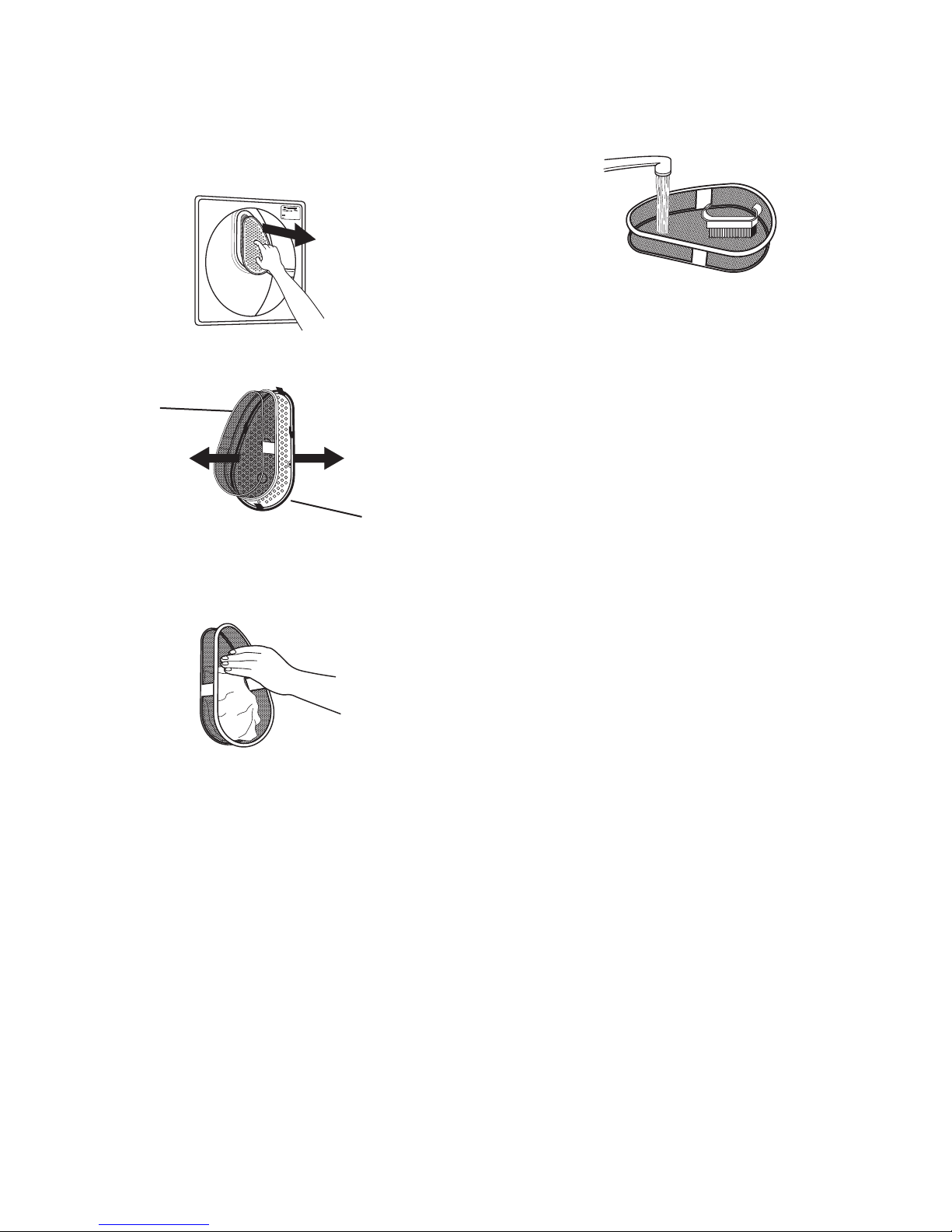
CLEANING THE LINT SCREEN
B
Every load cleaning
The lint screen is located on the back wall of the dryer. Remove
lint before each load. A screen blocked by lint can increase
drying time.
To clean
1. Pull out the lint screen and its cover.
2. Separate the cover and the screen by squeezing the screen
and pulling on the cover at the same time.
A
A. Screen
B. Cover
3. Roll lint o the screen with your ngers. Do not rinse or wash
screen to remove lint. Wet lint is hard to remove.
To wash
1. Roll lint o the screen with your ngers.
2. Wet both sides of lint screen with hot water.
3. Wet a nylon brush with hot water and liquid detergent.
Scrub lint screen with the brush to remove residue buildup.
4. Rinse screen with hot water.
5. Thoroughly dry lint screen with a clean towel. Replace screen
in dryer.
CLEANING THE DRYER INTERIOR
To clean dryer drum
1. Apply a liquid, nonammable household cleaner to the stained
area and rub with a soft cloth until all excess dye is removed.
2. Wipe drum thoroughly with a damp cloth.
3. Tumble a load of clean cloths or towels to dry drum.
NOTE: Garments that contain unstable dyes, such as denim blue
jeans or brightly colored cotton items, may discolor the dryer
interior. These stains are not harmful to your dryer and will not
stain future loads of clothes. Dry unstable dye items inside out
to avoid dye transfer.
REMOVING ACCUMULATED LINT
From Inside the Dryer Cabinet
Lint should be removed every 2 years, or more often, depending
on dryer usage. Cleaning should be done by a qualied person.
From the Exhaust Vent
Lint should be removed every 2 years, or more often, depending
on dryer usage.
4. Put the lint screen and cover back together and push rmly
back into place.
IMPORTANT:
■ Do not run the dryer with the lint screen loose, damaged,
blocked, or missing. Doing so can cause overheating and
damage to both the dryer and fabrics.
■ If lint falls o the screen into the dryer during removal, check
the exhaust hood and remove lint. See “Venting Requirements”.
As needed cleaning
Laundry detergent and fabric softener residue can build up on
the lint screen. This buildup can cause longer drying times for your
clothes, or cause the dryer to stop before your load is completely
dry. The screen is probably clogged if lint falls o the screen.
Clean the lint screen (as outlined following) every 6 months, or
more frequently if it becomes clogged due to a residue buildup.
VACATION, STORAGE, AND MOVING CARE
Install and store your Laundry Center where it will not freeze.
Because some water may stay in the hoses, freezing can damage
your Laundry Center. If storing or moving your Laundry Center
during freezing weather, winterize it.
Non-use or vacation care
Operate your Laundry Center only when you are at home.
If you will be on vacation or not using your Laundry Center
for an extended period of time, you should:
■ Unplug Laundry Center or disconnect power.
■ Turn o the water supply to the washer. This helps avoid
accidental ooding (due to a water pressure surge) while
you are away.
To winterize Laundry Center
1. Shut o both water faucets.
2. Disconnect and drain water inlet hoses.
3. Put 1 qt (1 L) of R.V.-type antifreeze in the basket.
4. Run washer on a drain and spin setting for about 30 seconds
to mix the antifreeze and water.
5. Unplug Laundry Center or disconnect power.
29
To use Laundry Center again
1. Flush water pipes and hoses.
2. Reconnect water inlet hoses.
3. Turn on both water faucets.
4. Plug in Laundry Center or reconnect power.
5. Run the washer through a complete cycle with 1 cup (250 mL)
of detergent to clean out antifreeze.
To transport the Laundry Center
1. Shut o both water faucets.
2. Disconnect and drain water inlet hoses.
3. If Laundry Center will be moved during freezing weather,
put a qt (1 L) of R.V.-type antifreeze in the basket. Run washer
on a spin setting for about 30 seconds to mix the antifreeze
and water.
4. Disconnect the drain hose from the drain system.
5. Unplug Laundry Center or disconnect power. Disconnect wiring
if Laundry Center is direct wired (240 volt model only).
6. Disconnect the exhaust vent.
7. Wash lint screen.
8. Make sure leveling legs are secure.
9. Place the inlet hoses into the basket.
10. Place the foam packing ring (removed during installation)
in the washer to keep the washer tub stable during transport.
11. Drape the power cord and drain hose over edge
and into the basket.
12. Use tape to secure the washer lid and dryer door.
Reinstalling your Laundry Center
1. Follow the “Installation Instructions” to locate, level, and
connect the Laundry Center.
2. Run the washer through a complete cycle with 1 scoop or
capful of detergent to clean the washer and remove the
antifreeze, if used.
30
 Loading...