

Kenmore 11068722700, 11068732700, 11068822700, 11068832700, 11068837700 Installation Guide
...
27" (69CM) ELECTRIC DRYER
INSTALLATION INSTRUCTIONS
INSTRUCCIONES DE INSTALACION PARA LA
SECADORA ELI_CTRICA DE 27" (69 CM)
Table of Contents/indice
DRYER SAFETY ............................................... 1
INSTALLATION INSTRUCTIONS .................... 2
Tools and Parts ............................................. 2
Location Requirements ................................ 2
Electrical Requirements ................................ 3
Electrical Connection .................................... 5
Venting Requirements ................................. 10
Plan Vent System ........................................ 11
Install Vent System ...................................... 12
Install Leveling Legs .................................... 12
Connect Vent ............................................... 13
Level Dryer .................................................. 13
Complete Installation .................................. 13
SERVICE NUMBERS ................. BACK COVER
SEGURIDAD DE LA SECADORA .................. 14
INSTRUCCIONES DE INSTALACION ........... 14
Herramientas y piezas ................................. 14
Requisitos de ubicacion .............................. 15
Requisitos el_ctricos .................................... 16
Conexi6n el_ctrica ....................................... 18
Requisitos de ventilacion ............................. 23
Planificaci6n del sistema de ventilaci6n......24
Instalacion del sistema de ventilaci6n .........26
Instalaci6n de las patas niveladoras ............ 26
Conexi6n del ducto de escape .................... 26
Nivelacion de la secadora ............................ 26
Complete la instalaci6n ............................... 27
NUMEROS DE SERVICIO CONTRAPORTADA
DRYERSAFETY
Your safety and the safety of others are very important.
We have provided many important safety messages in this manual and on your appliance. Always read and obey all safety
messages.
This is the safety alert symbol.
This symbol alerts you to potential hazards that can kill or hurt you and others.
All safety messages will follow the safety alert symbol and either the word "DANGER" or "WARNING."
These words mean:
You can be killed or seriously injured if you don't immediately
follow instructions.
You can be killed or seriously injured if you don't follow
instructions.
All safety messages will tell you what the potential hazard is, tell you how to reduce the chance of injury, and tell you what can
happen if the instructions are not followed.
8576656
INSTALLATION INSTRUCTIONS
Gather the required tools and parts before starting installation.
Read and follow the instructions provided with any tools listed
here.
Flat-blade screwdriver
#2 Phillips screwdriver
Adjustable wrench that
opens to 1" (2.5 cm) or
hex-head socket wrench
(for adjusting dryer feet)
Wire stripper (for direct
wire installations)
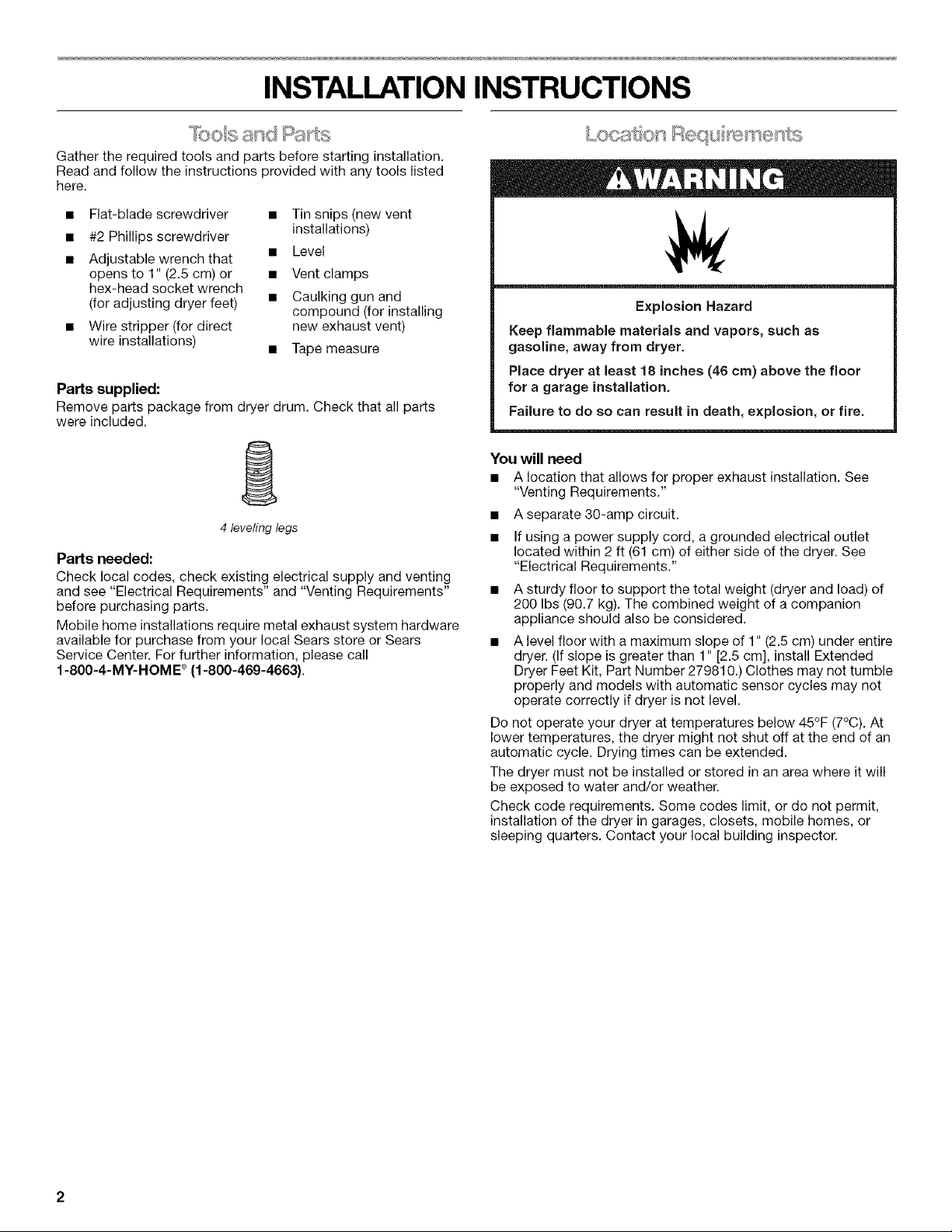
Parts supplied:
Remove parts package from dryer drum. Check that all parts
were included.
• Tin snips(new vent
installations)
• Level
• Vent clamps
• Caulking gun and
compound (for installing
new exhaust vent)
• Tape measure
1
4 leveling legs
Parts needed:
Check local codes, check existing electrical supply and venting
and see "Electrical Requirements" and "Venting Requirements"
before purchasing parts.
Mobile home installations require metal exhaust system hardware
available for purchase from your local Sears store or Sears
Service Center. For further information, please call
1-80O-4-MY-HOME ®(1-800-469-4663).
Explosion Hazard
Keep flammable materials and vapors, such as
gasoline, away from dryer.
Place dryer at least 18 inches (46 cm) above the floor
for a garage installation,
Failure to do so can result in death, explosion, or fire.
You will need
• A location that allows for proper exhaust installation. See
"Venting Requirements."
• Aseparate 30-amp circuit.
• If using a power supply cord, a grounded electrical outlet
located within 2 ft (61 cm) of either side of the dryer. See
"Electrical Requirements."
• A sturdy floor to support the total weight (dryer and load) of
200 Ibs (90.7 kg). The combined weight of a companion
appliance should also be considered.
• A level floor with a maximum slope of 1" (2.5 cm) under entire
dryer. (If slope is greater than 1" [2.5 cm], install Extended
Dryer Feet Kit, Part Number 279810.) Clothes may not tumble
properly and models with automatic sensor cycles may not
operate correctly if dryer is not level.
Do not operate your dryer at temperatures below 45°F (7°C). At
lower temperatures, the dryer might not shut off at the end of an
automatic cycle. Drying times can be extended.
The dryer must not be installed or stored in an area where it will
be exposed to water and/or weather.
Check code requirements. Some codes limit, or do not permit,
installation of the dryer in garages, closets, mobile homes, or
sleeping quarters. Contact your local building inspector.
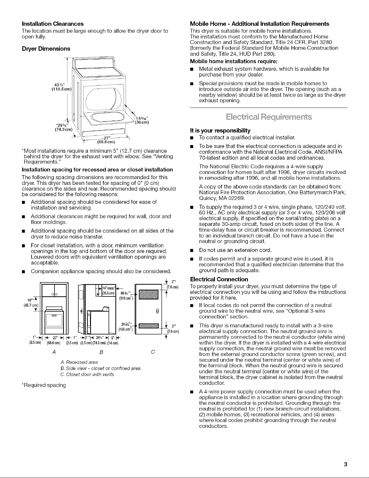
Installation Clearances
The location must be large enough to allow the dryer door to
open fully.
Dryer Dimensions
43½"
(110.5cmi
*291/4"
(74.3cm)
(68.6cm)
*Most installations require a minimum 5" (12.7 cm) clearance
behind the dryer for the exhaust vent with elbow. See "Venting
Requirements."
Installation spacing for recessed area or closet installation
The following spacing dimensions are recommended for this
dryer. This dryer has been tested for spacing of 0" (0 cm)
clearance on the sides and rear. Recommended spacing should
be considered for the following reasons:
• Additional spacing should be considered for ease of
installation and servicing.
• Additional clearances might be required for wall, door and
floor moldings.
• Additional spacing should be considered on all sides of the
dryer to reduce noise transfer.
• For closet installation, with a door, minimum ventilation
openings in the top and bottom of the door are required.
Louvered doors with equivalent ventilation openings are
acceptable.
• Companion appliance spacing should also be considered.
(7.6cm)
18"
48in/*4
(a_0om')II
f
o-ITo1 21:::,:;
(45.7c_) I ___ ,_
I"_ I _- 27"-__--I" +11"*I-__'J_")I s"
(2.5cm) (68.6cm) (2.5cm) (2.Scm)(74.3cm)(14cm)
B C
A. Recessed area
B. Side view - closet or confined area
C. Closet door with vents
*Required spacing
24in[*l[
(155crn2)U
(7.6 crn)
+
Mobile Home - Additional Installation Requirements
This dryer is suitable for mobile home installations.
The installation must conform to the Manufactured Home
Construction and Safety Standard, Title 24 CFR, Part 3280
(formerly the Federal Standard for Mobile Home Construction
and Safety, Title 24, HUD Part 280).
Mobile home installations require:
• Metal exhaust system hardware, which is available for
purchase from your dealer.
• Special provisions must be made in mobile homes to
introduce outside air into the dryer. The opening (such as a
nearby window) should be at least twice as large as the dryer
exhaust opening.
It is your responsibility
• To contact a qualified electrical installer.
• To be sure that the electrical connection is adequate and in
conformance with the National Electrical Code, ANSI/NFPA
70-latest edition and all local codes and ordinances.
The National Electric Code requires a 4-wire supply
connection for homes built after 1996, dryer circuits involved
in remodeling after 1996, and all mobile home installations.
A copy of the above code standards can be obtained from:
National Fire Protection Association, One Batterymarch Park,
Quincy, MA 02269.
• To supply the required 3 or 4 wire, single phase, 120/240 volt,
60 Hz., AC only electrical supply (or 3 or 4 wire, 120/208 volt
electrical supply, if specified on the serial/rating plate) on a
separate 30-amp circuit, fused on both sides of the line. A
time-delay fuse or circuit breaker is recommended. Connect
to an individual branch circuit. Do not have a fuse in the
neutral or grounding circuit.
• Do not use an extension cord.
• If codes permit and a separate ground wire is used, it is
recommended that a qualified electrician determine that the
ground path is adequate.
3"*
Electrical Connection
To properly install your dryer, you must determine the type of
electrical connection you will be using and follow the instructions
provided for it here.
• If local codes do not permit the connection of a neutral
ground wire to the neutral wire, see "Optional 3-wire
connection" section.
3"*
This dryer is manufactured ready to install with a 3-wire
electrical supply connection. The neutral ground wire is
permanently connected to the neutral conductor (white wire)
within the dryer. If the dryer is installed with a 4-wire electrical
supply connection, the neutral ground wire must be removed
from the external ground conductor screw (green screw), and
secured under the neutral terminal (center or white wire) of
the terminal block. When the neutral ground wire is secured
under the neutral terminal (center or white wire) of the
terminal block, the dryer cabinet is isolated from the neutral
conductor.
A 4-wire power supply connection must be used when the
appliance is installed in a location where grounding through
the neutral conductor is prohibited. Grounding through the
neutral is prohibited for (1) new branch-circuit installations,
(2) mobile homes, (3) recreational vehicles, and (4) areas
where local codes prohibit grounding through the neutral
conductors.
Ifusingapowersupplycord:
UseaULlistedpowersupplycordkitmarkedforusewith
clothesdryers.Thekitshouldcontain:
[] AULlisted30-amppowersupplycord,rated
120/240voltminimum.ThecordshouldbetypeSRDor
SRDTandbeatleast4ft(1.22m)long.Thewiresthat
connecttothedryermustendinringterminalsorspade
terminalswithupturnedends.
[] AULlistedstrainrelief.
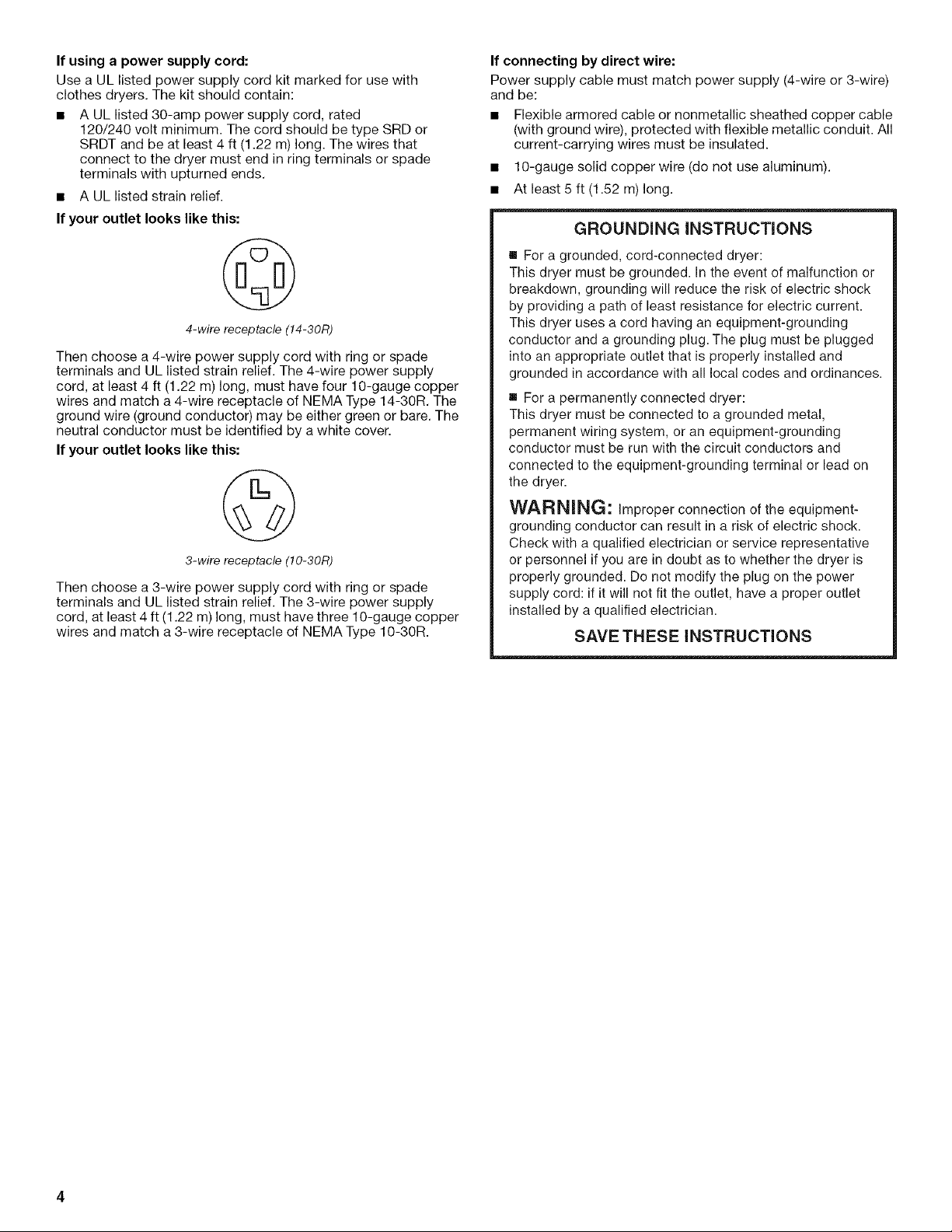
If your outlet looks like this:
4-wire receptacle (14-30R)
Then choose a 4-wire power supply cord with ring or spade
terminals and UL listed strain relief. The 4-wire power supply
cord, at least 4 ft (1.22 m) long, must have four 10-gauge copper
wires and match a 4-wire receptacle of NEMA Type 14-30R. The
ground wire (ground conductor) may be either green or bare. The
neutral conductor must be identified by a white cover.
If your outlet looks like this:
3-wire receptacle (10-30R)
Then choose a 3-wire power supply cord with ring or spade
terminals and UL listed strain relief. The 3-wire power supply
cord, at least 4 ft (1.22 m) long, must have three 10-gauge copper
wires and match a 3-wire receptacle of NEMA Type 10-30R.
If connecting by direct wire:
Power supply cable must match power supply (4-wire or 3-wire)
and be:
[] Flexible armored cable or nonmetallic sheathed copper cable
(with ground wire), protected with flexible metallic conduit. All
current-carrying wires must be insulated.
[] 10-gauge solid copper wire (do not use aluminum).
[] At least 5 ft (1.52 m) long.
GROUNDING iNSTRUCTIONS
[] For a grounded, cord-connected dryer:
This dryer must be grounded. In the event of malfunction or
breakdown, grounding will reduce the risk of electric shock
by providing a path of least resistance for electric current.
This dryer uses a cord having an equipment-grounding
conductor and a grounding plug. The plug must be plugged
into an appropriate outlet that is properly installed and
grounded in accordance with all local codes and ordinances.
[] For a permanently connected dryer:
This dryer must be connected to a grounded metal,
permanent wiring system, or an equipment-grounding
conductor must be run with the circuit conductors and
connected to the equipment-grounding terminal or lead on
the dryer.
WARNING: Improper connection of the equipment-
grounding conductor can result in a risk of electric shock.
Check with a qualified electrician or service representative
or personnel if you are in doubt as to whether the dryer is
properly grounded. Do not modify the plug on the power
supply cord: if it will not fit the outlet, have a proper outlet
installed by a qualified electrician.
SAVE THESE INSTRUCTIONS
(}<_" ®C_:O
Power Supply Cord
Fire Hazard
Use a new UL listed 30 amp power supply cord.
Use a UL listed strain relief.
Disconnect power before making electrical connections.
Connect neutral wire (white or center wire) to center
terminal (silver).
Ground wire (green or bare wire) must be connected to
green ground connector.
Connect remaining 2 supply wires to remaining
2 terminals (gold).
Securely tighten all electrical connections.
Failure to do so can result in death, fire, or
electrical shock.
Direct Wire
Fire Hazard
Use 10 gauge solid copper wire.
Use a UL listed strain relief.
Disconnect power before making electrical connections.
Connect neutral wire (white or center wire) to center
terminal (silver).
Ground wire (green or bare wire) must be connected to
green ground connector.
Connect remaining 2 supply wires to remaining
2 terminals (gold).
Securely tighten all electrical connections.
Failure to do so can result in death, fire, or
electrical shock.
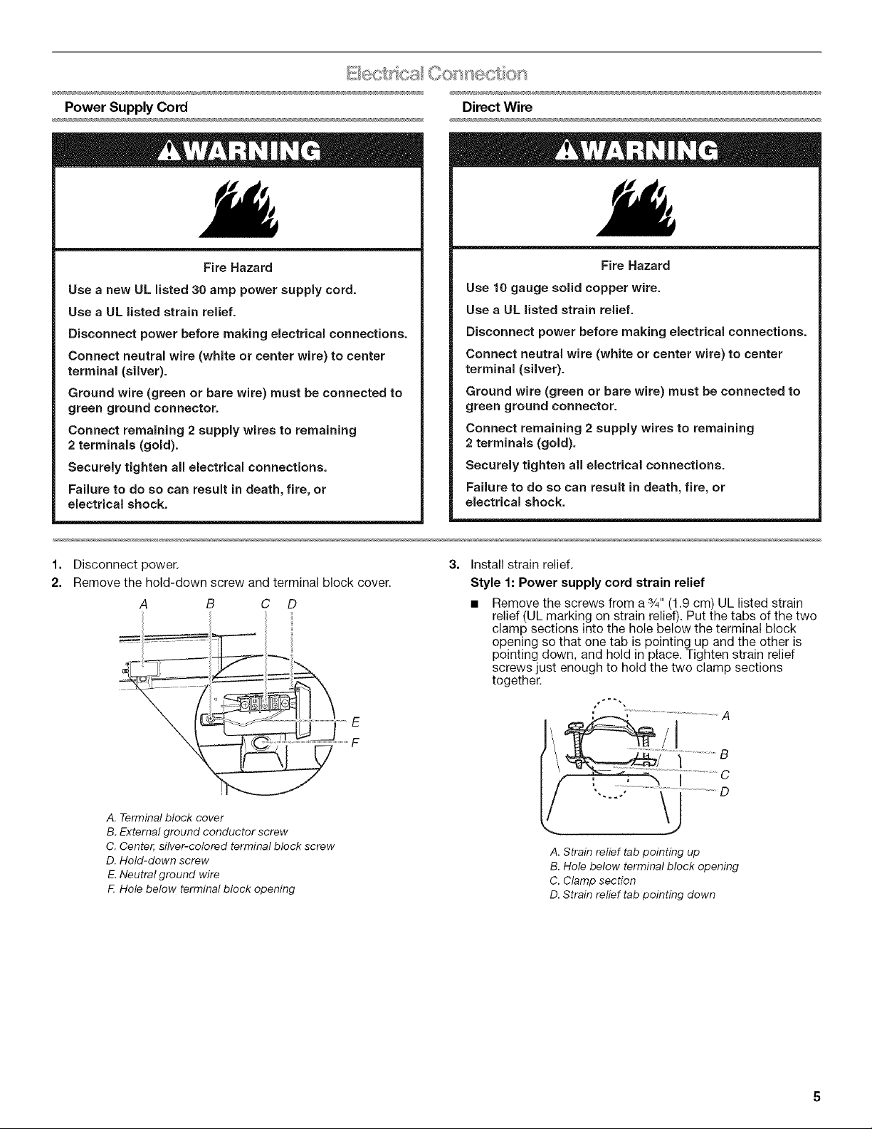
1. Disconnect power.
2. Remove the hold-down screw and terminal block cover.
A B C D
E
F
A. Terminal block cover
B. External ground conductor screw
C. Center, silver-colored terminal block screw
D. Hold-down screw
E.Neutral ground wire
F. Hole below terminal block opening
3= Install strain relief,
Style 1: Power supply cord strain relief
• Remove the screws from a 3/4"(1,9 cm) UL listed strain
relief (UL marking on strain relief). Put the tabs of the two
clamp sections into the hole below the terminal block
opening so that one tab is pointing up and the other is
pointing down, and hold in place. Tighten strain relief
screws just enough to hold the two clamp sections
together.
I ............................C
",.... ° _j ................D
A. Strain relief tab pointing up
B. Hole below terminal block opening
C. Clamp section
D. Strain relief tab pointing down
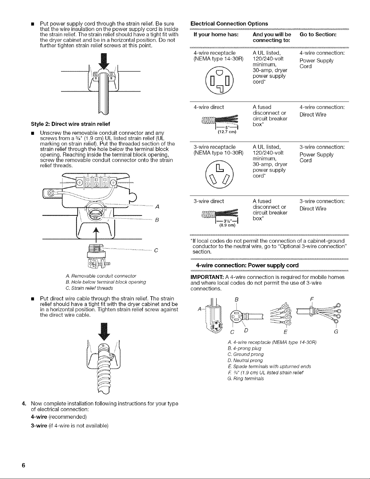
Put power supply cord through the strain relief. Be sure
that the wire insulation on the power supply cord is inside
the strain relief. The strain relief should have a tight fit with
the dryer cabinet and be in a horizontal position. Do not
further tighten strain relief screws at this point.
Style 2: Direct wire strain relief
• Unscrew the removable conduit connector and any
screws from a %" (1.9 cm) UL listed strain relief (UL
marking on strain relief). Put the threaded section of the
strain relief through the hole below the terminal block
opening. Reaching inside the terminal block opening,
screw the removable conduit connector onto the strain
relief threads.
Electrical Connection Options
If your home has: And you will be Go to Section:
connecting to:
4-wire receptacle
(NEMA type 14-30R)
A UL listed, 4-wire connection:
120/240-volt Power Supply
minimum, Cord
30-amp, dryer
power supply
cord*
4-wire direct A fused 4-wire connection:
disconnect or Direct Wire
circuit breakerbox*
(12.7 cm)
3-wire receptacle
(NEMA type 10-30R)
A UL listed, 3-wire connection:
120/240-volt Power Supply
minimum, Cord
30-amp, dryer
power supply
cord*
A. Removable conduit connector
B. Hole below terminal block opening
C. Strain relief threads
Put direct wire cable through the strain relief. The strain
relief should have a tight fit with the dryer cabinet and be
in a horizontal position. Tighten strain relief screw against
the direct wire cable.
3-wire direct A fused 3-wire connection:
disconnect or Direct Wire
box*
circuit breaker
*If local codes do not permit the connection of a cabinet-ground
conductor to the neutral wire, go to "Optional 3-wire connection"
section.
4-wire connection: Power supply cord
IMPORTANT: A 4-wire connection is required for mobile homes
and where local codes do not permit the use of 3-wire
connections.
B F
C D E G
A. 4-wire receptacle (NEMA type 14-30R)
B. 4-prong plug
C. Ground prong
D. Neutral prong
E.Spade terminals with upturned ends
F. _" (1.9 cm) UL Iisted strain relief
G. Ring terminals
4.
Now complete installation following instructions for your type
of electrical connection:
4-wire (recommended)
3-wire (if 4-wire is not available)
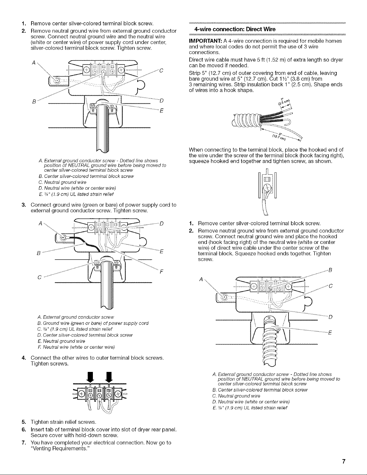
1=
Remove center silver-colored terminal block screw.
2.
Remove neutral ground wire from external ground conductor
screw. Connect neutral ground wire and the neutral wire
(white or center wire) of power supply cord under center,
silver-colored terminal block screw. Tighten screw.
A. External ground conductor screw - Dotted line shows
position of NEUTRAL ground wire before being moved to
center silver-colored terminal block screw
B. Center silver-colored terminal block screw
C. Neutral ground wire
D. Neutral wire (white or center wire)
E.3/4"(1.9 cm) UL listed strain relief
3=
Connect ground wire (green or bare) of power supply cord to
external ground conductor screw. Tighten screw.
4-wire connection: Direct Wire
IMPORTANT: A 4-wire connection is required for mobile homes
and where local codes do not permit the use of 3 wire
connections.
Direct wire cable must have 5 ft (1.52 m) of extra length so dryer
can be moved if needed.
Strip 5" (12.7 cm) of outer covering from end of cable, leaving
bare ground wire at 5" (12.7 cm). Cut 11/2'' (3.8 cm) from
3 remaining wires. Strip insulation back 1" (2.5 cm). Shape ends
of wires into a hook shape.
When connecting to the terminal block, place the hooked end of
the wire under the screw of the terminal block (hook facing right),
squeeze hooked end together and tighten screw, as shown.
A. External ground conductor screw
B. Ground wire (green or bare) of power supply cord
C. 3/4,,(1.9 cm) UL listed strain relief
D. Center silver-colored terminal block screw
E.Neutral ground wire
F Neutral wire (white or center wire)
4=
Connect the other wires to outer terminal block screws.
Tighten screws.
!! !!
1=
Remove center silver-colored terminal block screw.
2.
Remove neutral ground wire from external ground conductor
screw. Connect neutral ground wire and place the hooked
end (hook facing right) of the neutral wire (white or center
wire) of direct wire cable under the center screw of the
terminal block. Squeeze hooked ends together. Tighten
screw.
A. External ground conductor screw - Dotted line shows
position of NEUTRAL ground wire before being moved to
center silver-colored terminal block screw
B. Center silver-colored terminal block screw
C. Neutral ground wire
D. Neutral wire (white or center wire)
E.3/4.(!.9 cm) UL listed strain relief
5. Tighten strain relief screws.
6. Insert tab of terminal block cover into slot of dryer rear panel.
Secure cover with hold-down screw.
7. You have completed your electrical connection. Now go to
"Venting Requirements."
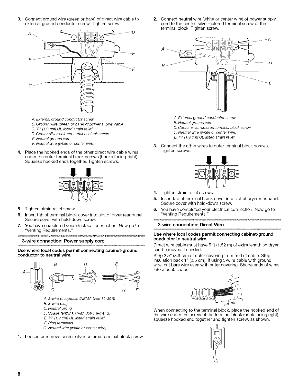
3. Connect ground wire (green or bare) of direct wire cable to
external ground conductor screw. Tighten screw.
2. Connect neutral wire (white or center wire) of power supply
cord to the center, silver-colored terminal screw of the
terminal block. Tighten screw.
A. External ground conductor screw
B. Ground wire (green or bare) of power supply cable
C. s/4"(1.9 cm) UL ilsted strain relief
D. Center silver-colored terminal block screw
E. Neutral ground wire
E Neutral wire (white or center wire)
4. Place the hooked ends of the other direct wire cable wires
under the outer terminal block screws (hooks facing right).
Squeeze hooked ends together. Tighten screws.
!! !!
5. Tighten strain relief screw.
6. Insert tab of terminal block cover into slot of dryer rear panel.
Secure cover with hold-down screw.
7. You have completed your electrical connection. Now go to
"Venting Requirements."
3-wire connection: Power supply cord
Use where local codes permit connecting cabinet-ground
conductor to neutral wire.
I /
A _
A. Externalground conductor screw
B. Neutralground wire
C. Centersilver-colored terminalblock screw
D. Neutralwire (white or center wire)
E._" (1.9 cm) UL listed strain relief
3.
Connect the other wires to outer terminal block screws.
Tighten screws.
!! !!
4. Tighten strain relief screws.
5. Insert tab of terminal block cover into slot of dryer rear panel.
Secure cover with hold-down screw.
6. You have completed your electrical connection. Now go to
"Venting Requirements."
3-wire connection: Direct Wire
Use where local codes permit connecting cabinet-ground
conductor to neutral wire.
Direct wire cable must have 5 ft (1.52 m) of extra length so dryer
can be moved if needed.
Strip 31/2'' (8.9 cm) of outer covering from end of cable. Strip
insulation back 1" (2.5 cm). If using 3-wire cable with ground
wire, cut bare wire even with outer covering. Shape ends of wires
into a hook shape.
1'
C G F
A. 3-wire receptacle (NEMA type 10-30R)
B. 3-wire plug
C. Neutral prong
D. Spade terminals with upturned ends
E. _" (1.9 cm) UL listed strain relief
F. Ring terminals
G. Neutral wire (white or center wire)
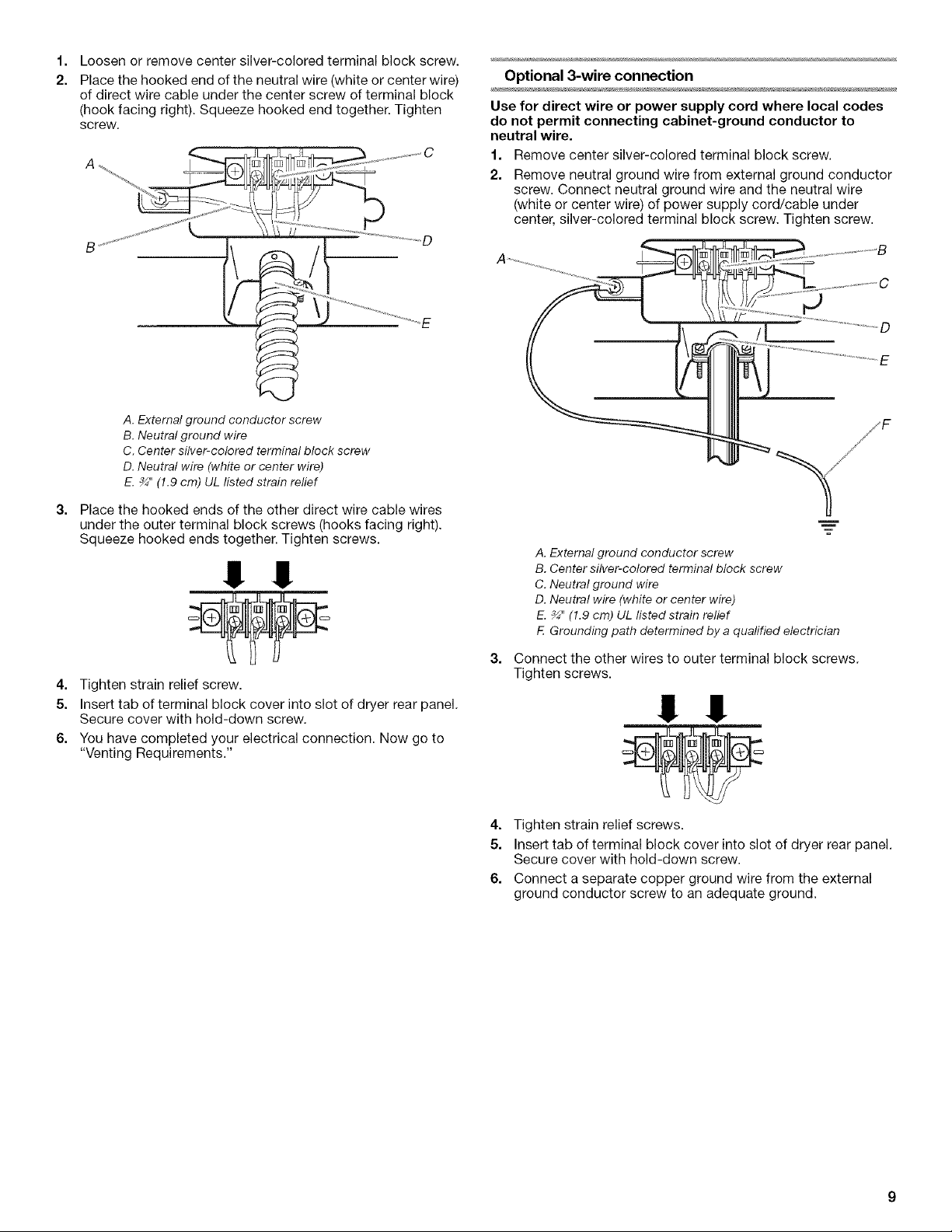
1. Loosen or remove center silver-colored terminal block screw.
When connecting to the terminal block, place the hooked end of
the wire under the screw of the terminal block (hook facing right),
squeeze hooked end together and tighten screw, as shown.
1=
Loosen or remove center silver-colored terminal block screw.
2.
Place the hooked end of the neutral wire (white or center wire)
of direct wire cable under the center screw of terminal block
(hook facing right). Squeeze hooked end together. Tighten
screw,
A. External ground conductor screw
B.Neutralground wire
C.Center silver-colored terminalblock screw
D.Neutral wire (whiteor center wire)
E._" (1.9 cm)UL listed strainrelief
3=
Place the hooked ends of the other direct wire cable wires
under the outer terminal block screws (hooks facing right).
Squeeze hooked ends together. Tighten screws.
!! !!
4. Tighten strain relief screw.
5. Insert tab of terminal block cover into slot of dryer rear panel,
Secure cover with hold-down screw,
6. You have completed your electrical connection. Now go to
"Venting Requirements."
Optional 3-wire connection
Use for direct wire or power supply cord where local codes
do not permit connecting cabinet-ground conductor to
neutral wire.
1. Remove center silver-colored terminal block screw.
2. Remove neutral ground wire from external ground conductor
screw. Connect neutral ground wire and the neutral wire
(white or center wire) of power supply cord/cable under
center, silver-colored terminal block screw. Tighten screw.
A. External ground conductor screw
B. Center silver-colored terminal block screw
C. Neutral ground wire
D. Neutral wire (white or center wire)
E. _" (1.9 cm) UL ilsted strain relief
E Grounding path determined by a qualified electrician
3=
Connect the other wires to outer terminal block screws,
Tighten screws.
!! !!
E
4. Tighten strain relief screws.
5. Insert tab of terminal block cover into slot of dryer rear panel.
Secure cover with hold-down screw.
6. Connect a separate copper ground wire from the external
ground conductor screw to an adequate ground.
 Loading...