

Kenmore 11066002010, 11066002011, 11068002010, 11068002011 Installation Guide

Dryer Installation instructions
Instrucciones de instalaci6n de la secadora
English / Espa_ol
Table of Contents / Jndice......3
P/N W10097003A
Sears Brands Management Corporation
Hoffman Estates, IL 60179 U.S.A.
www.kenmore.com
www.sears.com
Sears Canada inc.
Toronto, Ontario, Canada M5B 2B8
www.sears+ca

iNSTALLATiON NOTES NOTES CONCERNANT NOTAS SOBRE LA INSTALACI6N
LqNSTALLATION
Date of purchase:
Date of installation:
Installer:
Model number:
Serial number:
Date d'achat :
Date d'installation :
Installateur :
Num_ro de module :
Num_ro de s_rie :
Fecha de compra:
Fecha de instalaci6n:
Instalador:
N_mero de modelo:
N_mero de serie:
DRYER SAFETY
Your safety and the safety of others are very important.
We have provided many important safety messages in this manual and on your appliance. Always read and obey all safety
messages.
This is the safety alert symbol.
This symbol alerts you to potential hazards that can kill or hurt you and others.
All safety messages will follow the safety alert symbol and either the word "DANGER" or "WARNING."
These words mean:
You can be killed or seriously injured if you don't immediately
follow instructions.
You can be killed or seriously injured if you don't follow
instructions.
All safety messages will tell you what the potential hazard is, tell you how to reduce the chance of injury, and tell you what can
happen if the instructions are not followed.
WARNING - "Risk of Fire"
- Clothes dryer installation must be performed by a qualified installer,
- install the clothes dryer according to the manufacturer's instructions and local codes.
- Do not install a clothes dryer with flexible plastic venting materials. If flexible metal
(foil type) duct is installed, it must be of a specific type identified by the appliance
manufacturer as suitable for use with clothes dryers. Flexible venting materials are
known to collapse, be easily crushed, and trap lint. These conditions will obstruct
clothes dryer airflow and increase the risk of fire.
- To reduce the risk of severe injury or death, follow all installation instructions.
- Save these instructions.
2

Table of Contents
DRYER SAFETY ................................................................ 2
iNSTALLATiON REQUIREMENTS .................................... 3
Tools and Parts .................................................................... 3
Location Requirements ...................................................... 4
Electrical Requirements ...................................................... 5
Install Leveling Legs ........................................................... 6
Electrical Connection ........................................................... 7
VENTING .................................................................................... 13
Venting Requirements ....................................................... 13
Indice
SEGURIDAD DE LA SECADORA .................................. 20
REQUISITOS DE INSTALACION ................................... 21
Nerramientas y piezas ..................................................... 21
Requisitos de ubicacibn .................................................. 22
Requisitos el_ctricos ....................................................... 23
Instalaci6n de las paras niveladoras .............................. 24
Cone×i6n El_ctrica ........................................................... 25
VENTILACION .......................................................................... 31
Requisitos de ventilaci6n ................................................ 31
iNSTALLATiON REQUIREMENTS
Plan Vent System ............................................................... 14
Venting Kits ........................................................................ 15
Install Vent System ............................................................ 16
Connect Vent ..................................................................... 16
Level Dryer ......................................................................... 16
Complete Installation Checklist ....................................... 17
Reverse Door Swing (Optional) ........................................ 17
Troubleshooting ................................................................. 19
Planificaci6n del sistema de ventilaci6n ........................ 32
Juegos de ventiiaci6n ...................................................... 33
Instalaci6n del sistema de ventilaci6n ........................... 35
Cone×i6n del ducto de escape ....................................... 35
Nivelacibn de la secadora ............................................... 36
Lista de control de la instalaci6n terminada ................. 36
Cambio del sentido de abertura de la puerta ............... 37
Soluci6n de problemas ................................................... 39
Tools and Parts
Gather the required tools and parts before starting installation.
Read and follow the instructions provided with any tools listed
here.
Tools needed:
Flat-blade screwdriver
Wire stripper
(direct wire installations)
#2 Phillips screwdriver
Tin snips
(new vent installations)
Adjustable wrench that
opens to 1" (25 mm) or
hex-head socket wrench
Tape measure
Utility knife
Pliers
1/4" nut driver
(recommended)
db
Vent clamps
Level
Caulking gun and
compound (for installing
new exhaust vent)
Parts supplied:
Leveling legs (4)
Parts package is located in dryer drum. Check that all parts
are included.
Parts needed:
Check local codes. Check existing electrical supply and venting,
and read "Electrical Requirements" and "Venting Requirements"
before purchasing parts.
Mobile home installations require metal exhaust system
hardware, available for purchase from the dealer from whom
you purchased your dryer. For further information, please
reference the "Assistance or Service" section of the Dryer
User Instructions.
If using a power supply cord:
Use a UL listed power supply cord kit marked for use with
clothes dryers. The kit should contain:
[] A UL listed 30-amp power supply cord, rated 120/240 volt
minimum. The cord should be type SRD or SRDT and be
at least 4 ft. (1.22 m) long. The wires that connect to the
dryer must end in ring terminals or spade terminals with
upturned ends.
[] A UL listed strain relief.
[] If you are using power supply cord, a grounded electrical
outlet located within 2 ft. (610 mm) of either side of dryer.
See "Electrical Requirements."
[] A sturdy floor to support the total weight (dryer and load)
of 200 Ibs. (90.7 kg). The combined weight of a companion
appliance should also be considered.
[] Level floor with maximum slope of 1" (25 mm) under entire
dryer. (If slope is greater than 1" [25 mm], install Extended
Dryer Feet Kit, Part Number 279810.) If not level, clothes
may not tumble properly and automatic sensor cycles may
not operate correctly.
Do not operate your dryer at temperatures below 45°F (7°C). At
lower temperatures, the dryer might not shut off at the end of an
automatic cycle. Drying times can be extended.
The dryer must not be installed or stored in an area where it will
be exposed to water and/or weather.
Check code requirements. Some codes limit, or do not permit,
installation of the dryer in garages, closets, mobile homes, or
sleeping quarters. Contact your local building inspector.
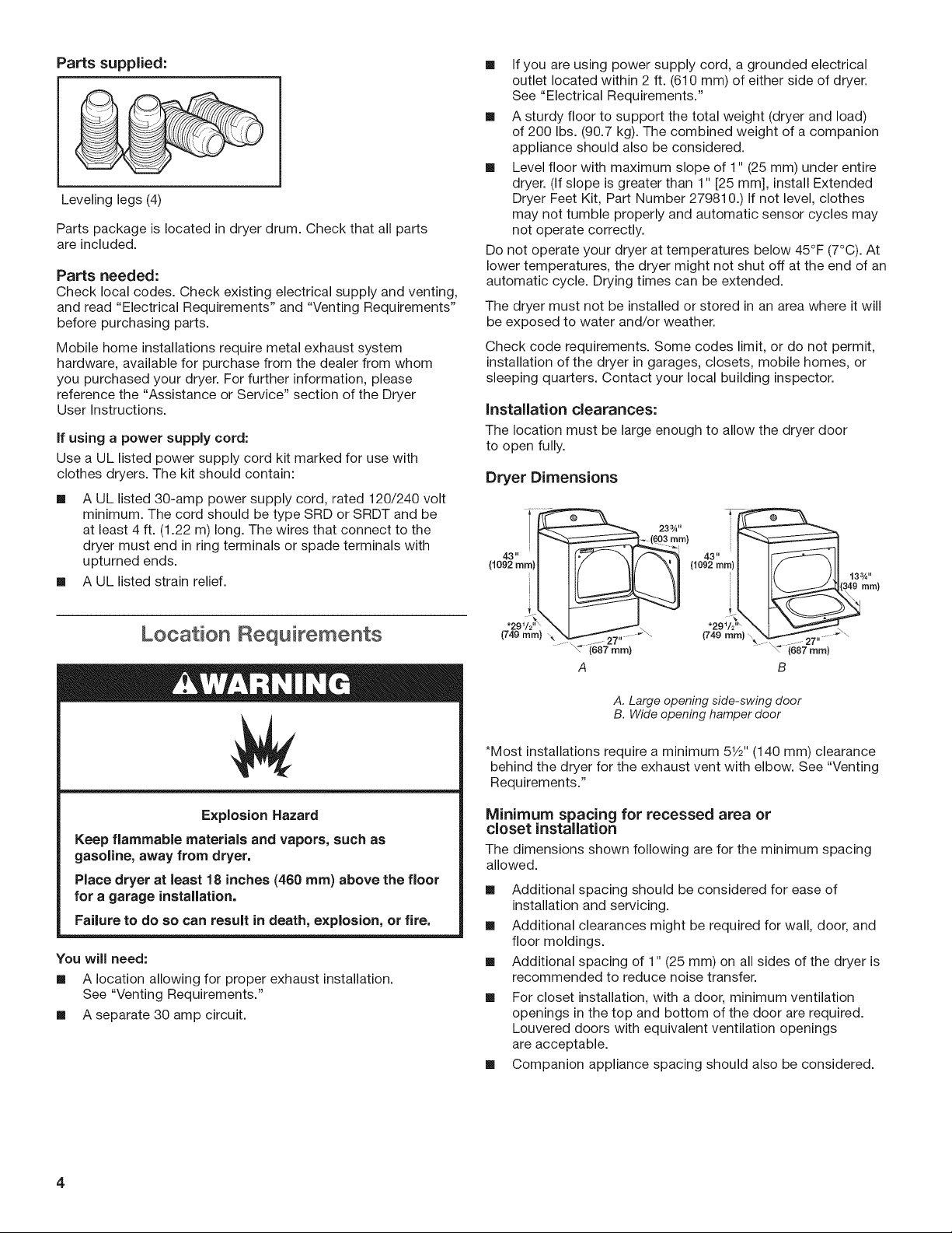
installation clearances:
The location must be large enough to allow the dryer door
to open fully.
Dryer Dimensions
23¾" _43" _ 43"
I ii__a49 ram)
Explosion Hazard
Keep flammable materials and vapors, such as
gasoline, away from dryer,
Place dryer at least 18 inches (460 ram) above the floor
for a garage installation,
Failure to do so can result in death, explosion, or fire,
You will need:
[] A location allowing for proper exhaust installation.
See "Venting Requirements."
[] A separate 30 amp circuit.
(749 ram) X _7" "\ (749 ram) \"_L.._.._"_27 . -\
\= i687 ram) _"(687 mm)
A B
A. Large opening side-swing door
B. Wide opening hamper door
*Most installations require a minimum 51/2"(140 mm) clearance
behind the dryer for the exhaust vent with elbow. See "Venting
Requirements."
Minimum spacing for recessed area or
closet installation
The dimensions shown following arefor the minimum spacing
allowed.
[] Additional spacing should be considered for ease of
installation and servicing.
[] Additional clearances might be required for wall, door, and
floor moldings.
[] Additional spacing of 1" (25 mm) on all sides of the dryer is
recommended to reduce noise transfer.
[] For closet installation, with a door, minimum ventilation
openings in the top and bottom of the door are required.
Louvered doors with equivalent ventilation openings
are acceptable.
[] Companion appliance spacing should also be considered.
4

Installation Spacing
_f 3 I1.
_ _=_in._
(310cm)2
24in=* _
(l cml
1"_ I_ 27"_ _ 1" -HI"*I<2_/,,,_15,J2,,*_
(25ram)(686mm)(25mm)(25mm)(743mm}(140ram)
A B
A. Recessed area
B. Side view - closet or confined area
C. Closet door with vents
*Additional spacing is recommended.
Mobile home =Additional installation requirements
This dryer is suitable for mobile home installations. The
installation must conform to the Manufactured Home
Construction and Safety Standard, Title 24 CFR, Part 3280
(formerly the Federal Standard for Mobile Home Construction and
Safety, Title 24, HUD Part 280) or the Canadian Manufactured
Home Standard CAN/CSA-Z240 MH.
[] Metal exhaust system hardware, available for purchase.
For further information, please reference the "Assistance or
Service" section of the "Dryer User Instructions."
[] Special provisions must be made in mobile homes to
introduce outside air into the dryer. The opening (such as a
nearby window) should be at least twice as large as the dryer
exhaust opening.
-_6mm)
(76mm)
-T
E(ectdca( Requirements
Electrical Connection
To properly install your dryer, you must determine the type of
electrical connection you will be using and follow the instructions
provided for it here.
[] If local codes do not permit the connection of a neutral
ground wire to the neutral wire, see "Optional 3-wire
connection" section.
[] This dryer is manufactured ready to install with a 3-wire
electrical supply connection. The neutral ground wire is
permanently connected to the neutral conductor (white wire)
within the dryer. Ifthe dryer is installed with a 4-wire electrical
supply connection, the neutral ground wire must be removed
from the external ground connector screw (green screw), and
secured under the neutral terminal (center or white wire) of
the terminal block. When the neutral ground wire is secured
under the neutral terminal (center or white wire) of the
terminal block, the dryer cabinet is isolated from the neutral
conductor.
[] A 4-wire power supply connection must be used when the
dryer is installed in a location where grounding through
the neutral conductor is prohibited. Grounding through the
neutral is prohibited for (1) new branch-circuit installations,
(2) mobile homes, (3) recreational vehicles, and (4) areas
where local codes prohibit grounding through the neutral
conductors.
If using a power supply cord:
Use a UL listed power supply cord kit marked for use with
clothes dryers. The kit should contain:
[] A UL listed 30-amp power supply cord, rated 120/240 volt
minimum. The cord should be type SRD or SRDT and be
at least 4 ft. (1.22 m) long. The wires that connect to the
dryer must end in ring terminals or spade terminals with
upturned ends.
[] A UL listed strain relief.
it is your responsibility:
[] To contact a qualified electrical installer.
[] To be sure that the electrical connection is adequate and in
conformance with the National Electrical Code, ANSI/NFPA
70-latest edition and all local codes and ordinances.
The National Electrical Code requires a 4-wire power supply
connection for homes built after 1996, dryer circuits involved
in remodeling after 1996, and all mobile home installations.
A copy of the above code standards can be obtained from:
National Fire Protection Association, One Batterymarch Park,
Quincy, MA 02269.
[] To supply the required 3 or 4 wire, single phase, 120/240 volt,
60 Hz, AC only electrical supply (or 3 or 4 wire, 120/208 volt
electrical supply, if specified on the serial/rating plate) on a
separate 30-amp circuit, fused on both sides of the line. A
time-delay fuse or circuit breaker is recommended. Connect
to an individual branch circuit. Do not have a fuse in the
neutral or grounding circuit.
[] Do not use an extension cord.
[] If codes permit and a separate ground wire is used, it is
recommended that a qualified electrician determine that the
ground path is adequate.
if your outlet looks like this:
Then choose a 4-wire power supply cord
with ring or spade terminals and UL listed
strain relief. The 4-wire power supply cord,
at least 4 ft. (1.22 m) long, must have
4 10-gauge solid copper wires and match
4-wire receptacle
(14-30R)
If your outlet looks like this:
3-wire receptacle
(10-30R)
If connecting by direct wire:
Power supply cable must match power supply (4-wire or 3-wire)
and be:
[] Flexible armored cable or nonmetallic sheathed copper cable
(with ground wire), covered with flexible metallic conduit. All
current-carrying wires must be insulated.
[] 10-gauge solid copper wire (do not use aluminum).
[] At least 5 ft. (1.52 m) long.
a 4-wire receptacle of NEMA Type 14-30 R.
The ground wire (ground conductor) may be
either green or bare. The neutral conductor
must be identified by a white cover.
Then choose a 3-wire power supply cord with
ring or spade terminals and UL listed strain
relief. The 3-wire power supply cord, at least
4 ft. (1.22 m) long, must have 3 10-gauge solid
copper wires and match a 3-wire receptacle of
NEMA Type 10-30R.

GROUNDING iNSTRUCTiONS
[] For a grounded, cord-connected dryer:
This dryer must be grounded. In the event of malfunction or
breakdown, grounding will reduce the risk of electric shock
by providing a path of least resistance for electric current.
This dryer uses a cord having an equipment-grounding
conductor and a grounding plug. The plug must be plugged
into an appropriate outlet that is properly installed and
grounded in accordance with all local codes and ordinances.
[] For a permanently connected dryer:
This dryer must be connected to a grounded metal,
permanent wiring system, or an equipment-grounding
conductor must be run with the circuit conductors and
connected to the equipment-grounding terminal or lead on
the dryer.
WARNING: Improper connection of the equipment-
grounding conductor can result in a risk of electric shock.
Check with a qualified electrician or service representative
or personnel if you are in doubt as to whether the dryer is
properly grounded. Do not modify the plug on the power
supply cord: if it will not fit the outlet, have a proper outlet
installed by a qualified electrician.
SAVE THESE iNSTRUCTiONS
2. Screw in leveling legs
diamond
marking
Examine leveling legs, find diamond marking. Screw legs into
leg holes by hand, use a wrench to finish turning legs until
diamond marking is no longer visible.
Now stand the dryer on its feet. Slide the dryer until it is
close to its final location. Leave enough room to connect the
exhaust vent.
For mobile home use
Gas dryers must be securely fastened to the floor.
mnstaH Leve_ing Legs
Excessive Weight Hazard
Use two or more people to move and install dryer,
Failure to do so can result in back or other injury,
1. Prepare dryer for leveling legs
\
Mobile home installations require a Mobile Home Installation
Hold-down Kit. For ordering information please reference the
"Dryer User Instructions."
To avoid damaging floor, use a large flat piece of cardboard
from dryer carton; place under entire back edge of dryer.
Firmly grasp dryer body (not console panel) and gently lay
dryer down on cardboard.
6

Emectrica[ Connection
Power Supply Cord Direct Wire
Fire Hazard
Use a new UL listed 30 amp power supply cord.
Use a UL listed strain relief.
Disconnect power before making electrical connections.
Connect neutral wire (white or center wire) to center
terminal (silver).
Ground wire (green or bare wire) must be connected to
green ground connector.
Connect remaining 2 supply wires to remaining
2 terminals (gold).
Securely tighten all electrical connections.
Failure to do so can result in death, fire, or
electrical shock.
Electrical Connection Options
1. Choose electrical connection type
Power supply cord 4-wire receptacle
(NEMA Type 14-30R): Go to steps 1-2 on
page 8 for power supply cord strain relief:
then steps 3-6 for 4-wire Power Supply
Cord Connection section. Then, go to
Venting Requirements.
Power supply cord 3=wire receptacle
(NEMA Type 10=30R): Go to steps 1-2 on
page 8 for power supply cord strain relief:
then steps 3-5 for 3-wire Power Supply
Cord Connection section.
Then go to Venting Requirements.
Fire Hazard
Use 10 gauge solid copper wire.
Use a UL listed strain relief.
Disconnect power before making electrical connections.
Connect neutral wire (white or center wire) to center
terminal (silver).
Ground wire (green or bare wire) must be connected to
green ground connector.
Connect remaining 2 supply wires to remaining
2 terminals (gold).
Securely tighten all electrical connections.
Failure to do so can result in death, fire, or
electrical shock.
2. Remove terminal block cover
B E C
F
4-wire direct connection: Go to steps
1=2 on page 10 for direct wire strain re=
lief: then steps 3-8 for 4-wire Direct Wire
Connection section. Then go to Venting
Requirements.
3-wire direct connection: Go to steps
1-2 on page 10 for direct wire strain relief:
then steps 3-7 for 3-wire Direct Wire
Connection section. Then go to Venting
Requirements.
NOTE: If local codes do not permit connection of a
cabinet-ground conductor to neutral wire, go to "Optional
3-wire Connection" section. This connection may be
used with either a power supply cord or a direct wire
connection.
Before you start, disconnect power. Remove hold-down
screw (D) and terminal block cover (A).
A. Terminal block cover
B. External ground conductor screw
C. Center terminal block screw
D. Hold-down screw
E. Neutral ground wire
E Hole below terminal block cover

Power SuppMy Cord Connection
Power supply cord strain relief
1. Attach power supply cord
strain relief
C
D
Remove the screws from a 3/4" (19 mm) UL listed strain relief
(UL marking on strain relief). Put the tabs of the two clamp
sections (C) into the hole below the terminal block opening
(B) so that one tab is pointing up (A) and the other is pointing
down (D), and hold in place. Tighten strain relief screws just
enough to hold the two clamp sections (C) together.
Attach power supply cord
to strain relief
4owire Power Supply Cord Connection
IMPORTANT: A 4-wire connection is required for mobile
homes and where local codes do not permit the use of 3-wire
connections.
A B
c
A. 4-wire receptacle (NEMA type 14-30R)
B. 4-prong plug
C. Ground prong
D. Neutral prong
E. Spade terminals with upturned ends
F. 3/4" (19 mm) UL listed strain relief
G. Ring terminals
E G
. Prepare to connect neutral
ground wire and neutral wire.
F
U
Put power supply cord through the strain relief. Be sure that
the wire insulation on the power supply cord is inside the
strain relief. The strain relief should have a tight fit with the
dryer cabinet and be in a horizontal position. Do not further
tighten strain relief screws at this point.
For 3-wire power supply cord connection, see 3-wire Power
Supply Cord Connection on page 9.
For 4-wire power supply cord connection, see 4-wire Power
Supply Cord Connection on this page.
Remove center terminal block screw (B).
Remove neutral ground wire (E) from external ground
conductor screw (A).
Connect neutral ground wire
and neutral wire
Connect neutral ground wire (E) and neutral wire (white or
center) (C) of power supply cord under center terminal block
screw (B). Tighten screw.
8

Connect ground wire (F) (green or bare) of power supply cord
to external ground conductor screw (A). Tighten screw.
Connect remaining wires to outer terminal block screws.
Tighten screws. Finally, reinsert tab of terminal block cover
into slot of dryer rear panel. Secure cover with hold-down
screw. Now, go to Venting Requirements.
3owire Power Supply Cord Connection
Use where local codes permit connecting cabinet-ground
conductor to neutral wire.
E
A
Remove center terminal block screw (B).
Connect neutral wire (white or center) (C) of power supply cord
to center terminal block screw (B). Tighten screw.
Connect remaining wires
B D
C
A. 3-wire receptacle (NEMA type 10-30R)
B. 3-wire plug
C. Neutral prong
D. Spade terminals with upturned ends
E. 3/4" (19 mm) UL fisted strain relief
F. Ring terminals
G.Neutral (white or center wire)
G _
Connect remaining wires to outer terminal block screws.
Tighten screws. Finally, reinsert tab of terminal block cover
into slot of dryer rear panel. Secure cover with hold-down
screw. Now, go to Venting Requirements.

Direct Wire Connection
Direct wire strain relief
Unscrew the removable conduit connector (A) and any
screws from a 3/4" (19 mm) UL listed strain relief (UL marking
on strain relief). Put the threaded section of the strain relief
(C) through the hole below the terminal block opening (B).
Reaching inside the terminal block opening, screw the
removable conduit connector (A) onto the strain relief threads.
to strain relief
4owire Direct Wire Connection
IMPORTANT: A 4-wire connection is required for mobile
homes and where local codes do not permit 3-wire
connections.
1. Prepare your 4-wire cable for
direct connection
Direct wire cable must have 5 ft. (1.52 m) of extra length so
dryer may be moved if needed.
Strip 5" (127 mm) of outer covering from end of cable,
leaving bare ground wire at 5" (127 mm). Cut 11/2'' (38 mm)
from remaining 3 wires. Strip insulation back 1" (25 mm).
Shape ends of wires into hooks.
Put direct wire cable through the strain relief. The strain
relief should have a tight fit with the dryer cabinet and be in
a horizontal position. Tighten strain relief screw against the
direct wire cable.
For 3-wire direct wire connection, see 3-wire Direct Wire
Connection on page 11.
For 4-wire direct wire connection, see 4-wire Direct Wire
Connection on this page.
To connect wires to terminal block, place hooked end of
wire under terminal block screw, facing to the right, squeeze
hooked end together and tighten screw.
ground wire and neutral wire
Remove center terminal block screw (B). Remove neutral
ground wire (E) from external ground conductor screw (A).
10

3owire Direct Wire Connection
and neutral wire
Connect neutral ground wire (E) and place hooked end (hook
facing right) of neutral wire (white or center wire) (C) of direct
wire cable under center screw of terminal block (B). Squeeze
hooked ends together and tighten screw.
Use where local codes permit connecting cabinet-ground
conductor to neutral wire.
1, Prepare your 3-wire cable for
direct connection
Direct wire cable must have 5 ft. (1.52 m) of extra length so
dryer may be moved if needed.
Strip 31/2" (89 mm) of outer covering from end of cable. Strip
insulation back 1" (25 mm). If using 3-wire cable with ground
wire, cut bare wire even with outer covering. Shape wire ends
into hooks.
Connect ground wire (green or bare) (F) of direct wire cable
to external ground conductor screw (A). Tighten screw.
Place hooked ends of remaining direct wire cable wires
under outer terminal block screws (hooks facing right).
Squeeze hooked ends together and tighten screws. Finally,
reinsert tab of terminal block cover into slot of dryer rear
panel. Secure cover with hold-down screw. Now, go to
Venting Requirements.
To connect wires to terminal block, place hooked end of wire
under terminal block screw, facing to the right, squeeze
hooked end together and tighten screw.
"-<_ ...............B
Remove center terminal block screw (B).
11

_4, Connect neutral wire
Place hooked end of neutral wire (white or cente) (C) of direct
wire cable under center terminal block screw (B). Squeeze
hooked end together. Tighten screw.
Connect neutral ground wire
and neutral wire
Connect neutral ground wire (E) and neutral wire (white or
center wire) (C) of power supply cord or cable under center
terminal block screw (B). Tighten screw.
Place hooked ends of remaining direct wire cable wires
under outer terminal block screws (hooks facing right).
Squeeze hooked ends together and tighten screws. Finally,
reinsert tab of terminal block cover into slot of dryer rear
panel. Secure cover with hold-down screw. Now, go to
Venting Requirements.
Optionam 3owire Connection
You must verify with a qualified electrician that this
grounding method is acceptable before connecting.
Place hooked ends of remaining wires under outer terminal
block screws (hooks facing right). Tighten screws.
Connect a separate copper ground wire (G) from the external
ground conductor screw (A) to an adequate ground. Finally,
reinsert tab of terminal block cover into slot of dryer rear
panel. Secure cover with hold-down screw. Now, go to
Venting Requirements.
Remove center terminal block screw (B). Remove neutral
ground wire (E) from external ground conductor screw (A).
12
 Loading...