

Page 1
®
INSTALLA ON IN_
COMMERCIAL DRYER- or Electric
8575078 Sears Roebuck and Co=, Hoffman Estates, HL60179 U=S=A= www, sears,com
Page 2
Table of Contents
DRYER SAFETY ............................................................................ 2
iNSTALLATiON REQUIREMENTS .............................................. 4
Tools and Parts .......................................................................... 4
Location Requirements .............................................................. 4
Electrical Requirements ............................................................ 6
Gas Supply Requirements ........................................................ 7
Venting Requirements .............................................................. 8
iNSTALLATiON iNSTRUCTiONS = GAS DRYER .................. 10
Prepare the Dryer ...................................................................... 10
install Coin Slide and Coin Box ................................................ 10
Make Gas Connection .............................................................. 10
Connect Vent ............................................................................ 10
Complete Installation .............................................................. 11
INSTALLATION INSTRUCTIONS = ELECTRIC DRYER ........ 11
Prepare the Dryer ...................................................................... 11
Install Coin Slide and Coin Box ................................................ 11
Make Electrical Connection ...................................................... 12
Connect Vent ............................................................................ 16
Complete Installation .............................................................. 16
COIN BOX OPTIONS ............................................................... 17
Changing to a 30- or 60-Minute Timing Cam ........................ 17
Changing Vend Prices (for Coin Slide Mechanism
Provided with Dryer) ................................................................ 17
DRYER SAFETY
Your safety and the safety of others are very important.
We have provided many important safety messages in this manual and on your appliance. Always read and obey all safety
messages.
This isthe safety alert symbol.
This symbol alerts you to potential hazards that can kill or hurt you and others.
All safety messages will follow the safety alert symbol and either the word "DANGER" or "WARNING."
These words mean:
You can be killed or seriously injured if you don't immediately
follow instructions.
You can be killed or seriously injured if you don't follow
instructions.
All safety messages will tell you what the potential hazard is, tell you how to reduce the chance of injury, and tell you what can
happen if the instructions are not followed.
It (srecommended that the owner post, in a prominent location, instructions for the customer's use (n the event the customer smells
gas. This information should be obtained from your gas supplier.
Post the following warning in a prominent location.
Do not store or use gasoline or other flammable vapors and liquids in the vicinity of this or any other appliance.
I FOR YOUR SAFETY
Page 3
WARN(NG: For your safety, the information in this manua( must be followed to m(n(mize 1
the risk of fire or e×p(os(on, or to prevent property damage, persona( injury, or death. 1
- Do not store or use gasoline or other flammab(e vapors and Hqu(ds in the vicinity of this
or any other app(iance.
- WHAT TO DO IF YOU SMELL GAS:
®Do not try to Hght any appl(ance.
®Do not touch any e)ectr(ca( switch; do not use any phone in your bui(ding.
®C(ear the room, bui(ding, or area of aH occupants.
®Immediate(y call your gas supplier from a neighbor's phone. Follow the gas suppHer's
instructions.
®ff you cannot reach your gas supp(ier, call the fire department.
- hstaHation and service must be performed by a qualified installer, service agency, or
the gas supplier.
In the State of Massachusetts, the following installation instructions apply:
m Installations and repairs must be performed by a qualified or licensed contractor, plumber, or gasfitter qualified or licensed by
the State of Massachusetts.
m If using a ball valve, it shall be a T-handle type.
m A flexible gas connector, when used, must not exceed 3 feet.
iMPORTANT SAFETY iNSTRUCTiONS
WARNING: To reduce the risk of fire, electric shock, or injury to persons when using the dryer, follow basic precautions,
including the following:
m
Read all instructions before using the dryer.
m
Do not place items exposed to cooking oils in your dryer.
Items contaminated with cooking oils may contribute to
a chemical reaction that could cause a load to catch fire.
m Do not dry articles that have been previously cleaned in,
washed in, soaked in, or spotted with gasoline, dry-
cleaning solvents, other flammable, or explosive
substances as they give off vapors that could ignite or
explode.
m Do not allow children to play on or in the dryer. Close
supervision of children is necessary when the dryer is
used near children.
m Before the dryer is removed from service or discarded,
remove the door to the drying compartment.
m Do not reach into the dryer if the drum is moving.
m Do not instal! or store the dryer where it will be exposed
to the weather.
m Do not tamper with controls.
Do not repair or replace any part of the dryer or attempt
any servicing unless specifically recommended in this
Use and Care Guide or in published user-repair instruc-
tions that you understand and have the skills to carry out.
m Do not use fabric softeners or products to eliminate static
unless recommended by the manufacturer of the fabric
softener or product.
m Do not use heat to dry articles containing foam rubber or
similarly textured rubber-like materials.
m Clean lint screen before or after each load.
m Keep area around the exhaust opening and adjacent sur-
rounding areas free from the accumulation of lint,dust,
and dirt.
The interior of the dryer and exhaust vent should be
cleaned periodically by qualified service personnel.
See installation instructions for grounding requirements.
SAVE THESE iNSTRUCTiONS
I_,,'IPORTANT:The gas installation must conform with local codes, or in the absence of local codes, with the National Fuel Gas
Code, ANSI Z223.1/NFPA 54 or the Canadian Natural Gas and Propane Installation Code, CSA B149.1.
The dryer must be electrically grounded in accordance with local codes, or in the absence of local codes, with the National
Electrical Code, ANSI/NFPA 70 or Canadian Electrical Code, CSA C22.1.
Page 4
iNSTALLATiON REQUIREMENTS
Gather the required tools and parts before starting installation.
Tools needed
m 8" or 10" pipe wrench
m 8" or 10" adjustable wrench
m Flat-blade screwdriver
m Phillips screwdriver
m Adjustable wrench that opens to 1" (2.5 cm) or hex-head
socket wrench
m Level
m %6" socket wrench
m Utility knife
m Vent clamps
m Pipe-joint compound resistant to LP gas
m Caulk gun and caulk (for installing new exhaust vent)
m Pliers
m Putty knife
Parts supplied
Remove parts bag from dryer drum. Check that all parts were
included.
m Security key
m Foot boot
m Dryer foot
m 3 pin timing cam
m 6 pin timing cam
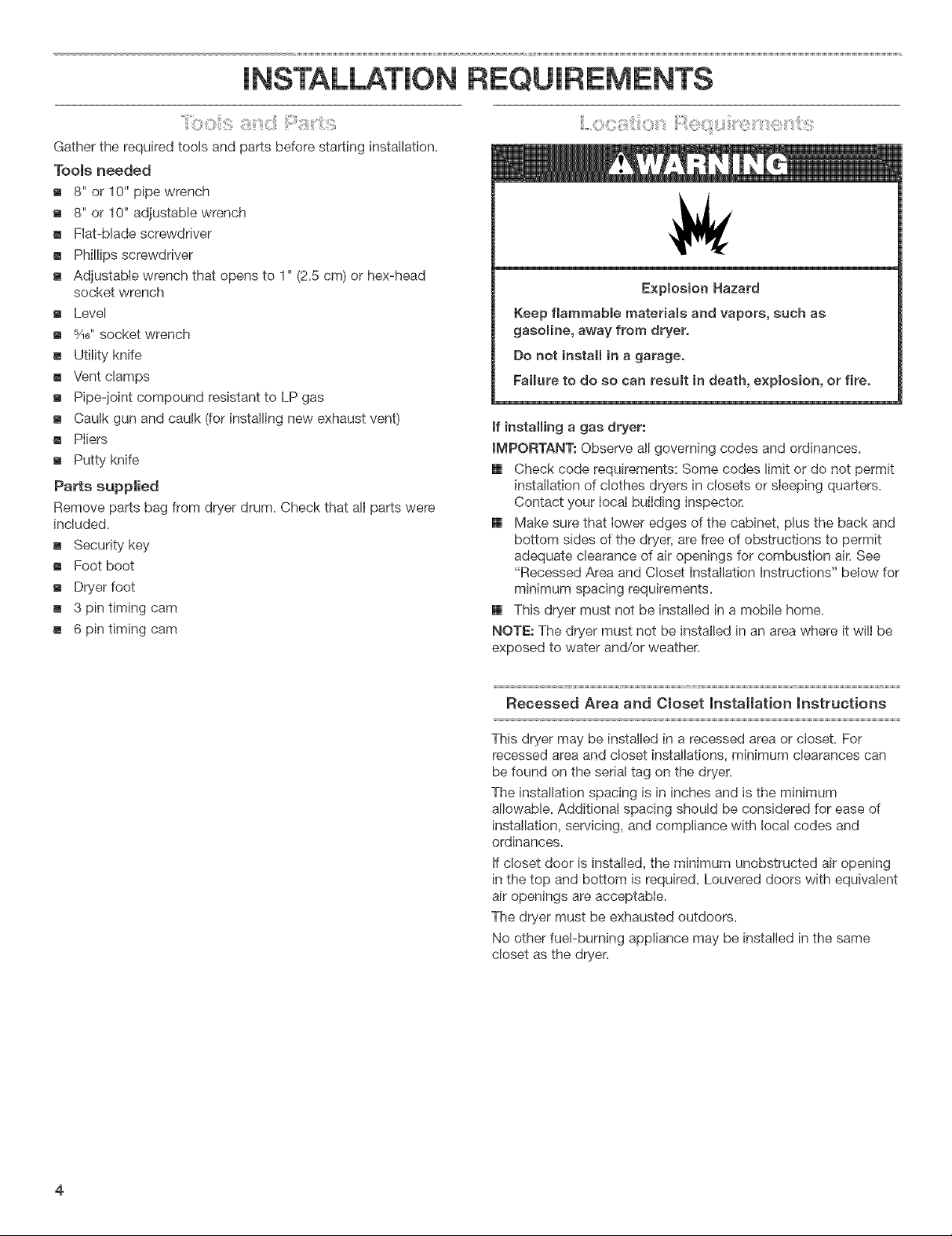
Explosion Hazard
Keep flammable materials and vapors, such as
gasomine, away from dryer.
Do not install in a garage.
Faimureto do so can resumt in death, expmosion, or fire.
If installing a gas dryer:
IMPORTANT: Observe all governing codes and ordinances.
[] Check code requirements: Some codes limit or do not permit
installation of clothes dryers in ciosets or sleeping quarters.
Contact your local building inspector.
[] Make sure that lower edges of the cabinet, plus the back and
bottom sides of the dryer, are free of obstructions to permit
adequate clearance of air openings for combustion air. See
"Recessed Area and Closet Installation Instructions" below for
minimum spacing requirements.
[] This dryer must not be installed in a mobile home.
NOTE: The dryer must not be installed in an area where it wilI be
exposed to water and/or weather.
Recessed Area and Ctoset Installation Instructions
This dryer may be installed in a recessed area or closet. For
recessed area and closet installations, minimum clearances can
be found on the serial tag on the dryer.
The installation spacing is in inches and is the minimum
allowable. Additional spacing should be considered for ease of
installation, servicing, and compliance with local codes and
ordinances.
If closet door is installed, the minimum unobstructed air opening
in the top and bottom is required. Louvered doors with equivalent
air openings are acceptable.
The dryer must be exhausted outdoors.
No other fuel-burning appliance may be installed in the same
closet as the dryer.
Page 5
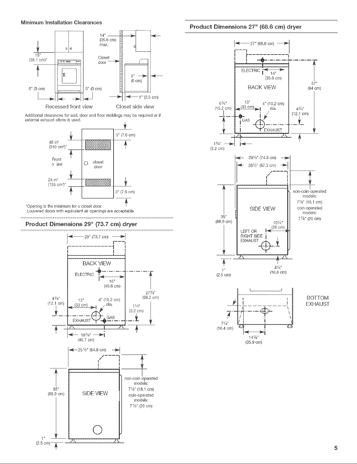
MinimuminstallationClearances
_ 4" --
(35.6 cm)
olO
15"
(3&1 cm)*
t
o"(ocm)
I
Recessed front view
Additional clearances for wall, door and floor moldings may be required or if
external exhaust elbow is used.
max.
Closet
door
0"
(O cm)
0" (0 cm)
1" (2.5 cm)
C}oset side view
g_
3" (7.6 cm)
48 in2
(310 cm_)*
Product Diraensions 27" (68,6 cra) dryer
-_--_27" (68.6 cm)
t -t:
ELECTRIC
(35.6 cm)
BACK VIEW
63/4"
13" 4" (10.2 cm)
_B dia.
i 2s7
(3.2 cm)
b<---
37 _
(94 ore)
Front
v law
24 in2
(155 cW)* _-
•Opening is the minimum for a closet door. J_
Louvered doors with equivalent air openings are acceptable.
i_
O closet
door
8" {7,6 cm/
Product Diraensions 29" {73,7 era} dryer
-_b----- 29" (73.7 cm)
1
I
m
BACK VEW
ELECTRIC _ ..............(40.6 ore) I
13" 4" (10.2 cm)
33 dia,
2_
18s&' _i
(46.7 cm)
_---251/2 ' (64.8 cm)
11/4``
(3.2 cm)
27 Y4"
(69.2 cm)
291/4' (74.3 cm) _-4_- I
26F*" (67.3 ore) _ll
SIDE VEW
35 _
(88.9 cm)
LEFT OR
RIGHT SIDE i
EXHAUST_o_
(2.5 cm)
71/4" /LL •
(18.4 cm) _ (_
14_z'
(35.9 cm)
1OW'
4V4"
(10.8 ore)
nomco_n-operated
models:
7Xd' (18.1 cm)
coin-operated
models:
7%" (20 cm)
BOTTOM
EXHAUST
(88.9 cm)
1 " --
(2,5cm)-_
35"
[/
I
r
SHDEVEW
O
non-coin-operated
models:
7W' (18.1 cm)
coin-operated
models:
7%" (20 cm)
Page 6
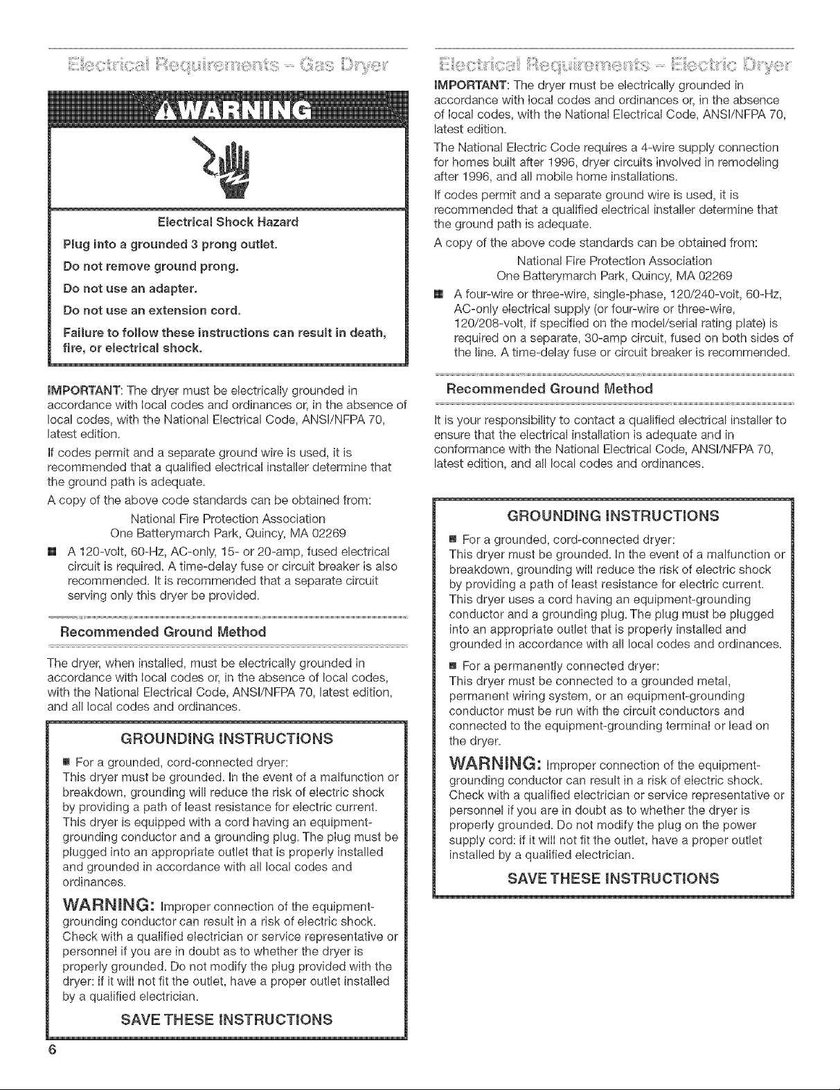
E(ectricatShockHazard
Plugintoagrounded3 prongoutlet.
Donotremovegroundprong,
Donotuseanadapter,
Donotuse an extension cord.
Failure to follow these instructions can result in death,
fire, or electrical shock.
:::::,:::: : ............
IMPORTANT: The dryer must be electricaly grounded in
accordance with local codes and ordinances or, in the absence
of local codes, with the National Electrical Code, ANSI/NFPA 70,
latest edition.
The National Electric Code requires a 4-wire supply connection
for homes built after 1996, dryer circuits involved in remode/ng
after 1996, and all mobile home installations.
If codes permit and a separate ground wire is used, it is
recommended that a qualfied electrical installer determine that
the ground path is adequate.
A copy of the above code standards can be obtained from:
National Fire Protection Association
One Batterymarch Park, Quincy, MA 02269
[] A four-wire or three-wire, single-phase, 120/240-volt, 60-Hz,
AC-only eIectrical suppty (or four-wire or three-wire,
120/208-volt, if specified on the mode!/serial rating plate) is
required on a separate, 30-amp circuit, fused on both sides of
the line. A time-delay fuse or circuit breaker is recommended.
IMPORTANT: The dryer must be electricaly grounded in
accordance with local codes and ordinances or, in the absence of
local codes, with the National Electrical Code, ANSI/NFPA 70,
latest edition.
If codes permit and a separate ground wire is used, it is
recommended that a qualfied electrical installer determine that
the ground path is adequate.
A copy of the above code standards can be obtained from:
National Fire Protection Association
One Batterymarch Park, Quincy, MA 02269
[] A 120-volt, 60-Hz, AC-only, 15- or 20-amp, fused electrical
circuit is required. A time-delay fuse or circuit breaker is also
recommended. It is recommended that a separate circuit
serving only this dryer be provided.
Recommended Ground Method
The dryer, when instaled, must be eIectricaly grounded in
accordance with local codes or, in the absence of local codes,
with the National Electrical Code, ANSI/NFPA 70, latest edition,
and all local codes and ordinances.
GROUNDING INSTRUCTIONS
_' For a grounded, cord-connected dryer:
This dryer must be grounded. In the event of a malfunction or
breakdown, grounding will reduce the risk of eiectdc shock
by providing a path of Ieast resistance for electric current.
This dryer is equipped with a cord having an equipment-
grounding conductor and a grounding plug. The pIug must be
plugged into an appropriate outlet that is properly installed
and grounded in accordance with all local codes and
ordinances.
Recommended Ground Method
It is your responsiblity to contact a qualfied electrical instaler to
ensure that the electrical installation is adequate and in
conformance with the National Electrical Code, ANSI/NFPA 70,
latest edition, and all local codes and ordinances.
GROUNDING INSTRUCTIONS
_' For a grounded, cord-connected dryer:
This dryer must be grounded. In the event of a malfunction or
breakdown, grounding will reduce the risk of electdc shock
by providing a path of Ieast resistance for electric current.
This dryer uses a cord having an equipment-grounding
conductor and a grounding plug. The plug must be pIugged
into an appropriate outlet that is properIy installed and
grounded in accordance with all local codes and ordinances.
For a permanently connected dryer:
This dryer must be connected to a grounded metal,
permanent wiring system, or an equipment-grounding
conductor must be run with the circuit conductors and
connected to the equipment-grounding terminal or lead on
the dryer.
W_RN_G: improper connection of the equipment-
grounding conductor can result in a risk of electric shock.
Check with a qualified electrician or service representative or
personnel if you are in doubt as to whether the dryer is
properly grounded. Do not modify the plug on the power
supply cord: if it wiII not fit the outlet, have a proper outlet
installed by a quaIified electrician.
SAVE THESE INSTRUCTIONS
WARNING-" Improper connection of the equipment-
grounding conductor can result in a risk of electric shock.
Check with a qualified electrician or service representative or
personneI if you are in doubt as to whether the dryer is
properly grounded. Do not modify the plug provided with the
dryer: if it wiII not fit the outlet, have a proper outlet installed
by a quaIified electrician.
SAVE THESE INSTRUCTIONS
6
Page 7

Explosion Hazard
Use a new ¢SA International approved gas supply line.
Install a shut-off valve.
SecureIy tighten all gas connections.
tf connected to LP, have a qualified person make sure
gas pressure does not exceed 13" (33 cm) water
column.
Examples of a quamified person include:
licensed heating personnel,
authorized gas company personnel, and
authorized service personnel.
Failure to do so can result in death, expmosion, or fire.
IMPORTANT: Observe all governing codes and ordinances.
This installation must conform with aH!ocal codes and
ordinances. In the absence of local codes, installation must
conform with American National Standard, National Fuel Gas
Code ANSI Z223.1/NFPA 54.
A copy of the above code standards can be obtained from:
National Fire Protection Association
One Batterymarch Park
Quincy, Massachusetts 02269
The design of this dryer has been certified by CSA International
for use at altitudes up to 10,000 feet (3048 m) above sea level at
the B.T.U. rating indicated on the model/serial piate. Burner input
adjustments are not required when the dryer is operated up to
this elevation.
When installed above 10,000 feet (3048 m), a four percent (4%)
reduction of the burner B.T.U. rating shown on the model/serial
plate is required for each 1,000 foot (305 m) increase in elevation.
For assistance when converting to other gas types and/or
installing above 10,000 feet (3048 m) elevation, contact your local
service company.
Gas Supply Line
Recommended method
[] Provide a gas supply line of 1/2"rigid (IPS) pipe to the dryer
location. Pipe joint compounds that resist the action of LP gas
must be used. Do not use TEFLON _t tape. With LP gas,
piping or tubing size can be 1/2"minimum. Usually, LP gas
suppiiers determine the size and materials used in the system.
Alternate method
[] The gas supply may also be connected using 3/8"approved
copper or aluminum tubing. Ifthe total [ength of the supply
line is more than 20 feet (6.1 m), larger tubing will be required.
If using natural gas, do not use copper tubing. Pipe joint
compounds that resist the action of LP gas must be used.
F_exib[e metal appliance connector:
[] It is recommended that a new flexible stainless steer gas line,
design-certified by AGA or CSA International, be used for
connecting the dryer to the gas supply line. (The gas pipe
which extends through the lower rear of the dryer is provided
with %" male pipe thread.)
[] Do not kink or damage the flexible stainless steel gas line
when moving the dryer.
Rigid pipe connection:
The rigid pipe connection requires a combination of pipe fittings
to obtain an in-line connection to the dryer.
Must include a shutoff valve:
The supply line must be equipped with a manual shutoff valve
installed within 6 ft. (1.8 m) of dryer in accordance with
National Fuel Gas Code, ANSI Z223.1/NFPA 54. This valve
should be located in the same room as the dryer. It should be
in a location that allows ease of opening and closing. Do not
block access to shutoff valve. The valve is for turning on or
shutting off gas to the dryer.
B
Type of Gas
This dryer is equipped for use with natural gas. It is design-
certified by CSA International for LP (propane and butane) gases
with appropriate conversion. No attempt shall be made to convert
the dryer from the gas specified on the serial/rating plate for use
with a different gas without consulting the serving gas supplier.
Conversion must be done by a qualified service technician. Gas
conversion kit part numbers are listed on the gas valve burner
base.
m ,,,.......
A. Gas supply line
B. Shutoff valve "open" position
C. To dryer
t(®TEFLON is a registered trademad_ of E,I, Du Pont De Nemours and Company,
Page 8
[] Installed in a confined area:
Ifthe dryer is instalbd in a confined area such as a bathroom
or closet, provision must be made for enough air for
combustion and ventilation. Check governing codes and
ordinances or refer to the ""Recessed Area and Cioset
Installation instructions" in the ""Location Reqiurements"
section.
Gas Supply Pressure Testing
A 1/8"NPT minimum plugged tapping, accessible for gauge
testing, must be installed immediately upstream of the gas supply
connection to the dryer.
The dryer must be disconnected from the gas suppJy piping
system during any pressure testing of the system at test
pressures in excess of 1/2psig.
Fire Hazard
Use a heavy metaJ vent.
Do not use a plastic vent,
Do not use a metal foil vent,
FaiJure to follow these instructions can result in death
or fire.
WARNING: To reduce the risk of fire, this dryer MUST BE
EXHAUSTED OUTDOORS.
[] The dryer vent must not be connected into any gas vent,
chimney, wall, ceiling, or a concealed space of a building.
[] Do not use an exhaust hood with a magnetic latch.
[] Do not install flexible metal vent in enclosed wails, ceilings
or floors.
[] 4" (10.2 cm) heavy metal vent and clamps must be used.
[] Use clamps to seal alljoints. Vent must not be connected or
secured with screws or other fastening devices which extend
into the interior of the vent. Do not use duct tape.
IMPORTANT: Observe all governing codes and ordinances.
Use a heavy metal vent. Do not use plastic or metal foil vent.
Rigid metal vent is recommended to prevent crushing and
kinking.
FIexibb metal vent must be fully extended and supported when
the dryer is in its final position. Remove excess fJexJbb meta! vent
to avoid sagging and kinking that may result in reduced airflow
and poor performance.
An exhaust hood should cap the vent to prevent rodents and
insects from entering the home or business.
Exhaust hood must be at bast 12" (30.5 cm) from the ground or
any object that may be in the path of the exhaust (such as
flowers, rocks or bushes}.
if using an existing vent system, clean lint from the entire length
of the system and make sure exhaust hood is not plugged with
lint. Replace any plastic or metal foil vent with rigid metal or
flexible metal vent.
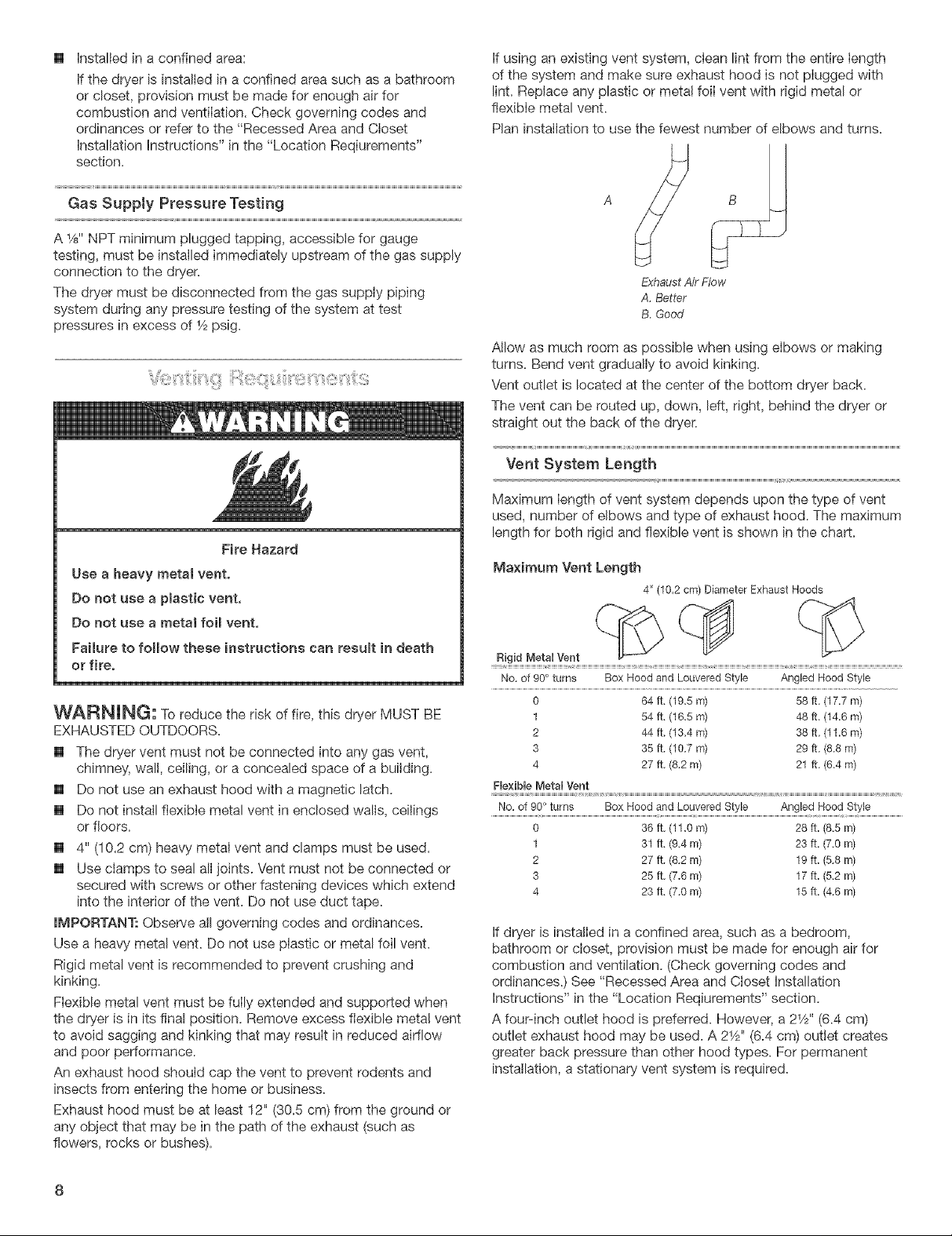
Plan installation to use the fewest number of elbows and turns.
ExhaustAirFlow
A.Better
B.Good
Allow as much room as possible when using elbows or making
turns. Bend vent gradually to avoid kinking.
Vent outlet is located at the center of the bottom dryer back.
The vent can be routed up, down, left, right, behind the dryer or
straight out the back of the dryer.
Vent System Length
Maximum length of vent system depends upon the type of vent
used, number of elbows and type of exhaust hood. The maximum
length for both rigid and flexible vent is shown in the chart.
Maximum Vent Length
4" (102 crn) Diameter Exhaust Hoods
Rigid Metal Vent
No. of 90 ° turns Box Hood and Louvered Style Angled Hood Style
0
1
2
3
4
Flexible MetalVent
No. of 90° turns Box Hood and Louvered Style Angled Hood Style
0 36 ft, (11,0 rn) 28 ft, (8.5 rn)
1 31 ft, (9,4 rn) 23 ft. (7,0 rn)
2 27 ft, (8,2 rn) 19 ft, (5,8 rn)
3 25 ft, (7,6 rn) 17 ft. (5,2 rn)
4 23 ft, (7.0 rn) 15 ft_ (4.6 rn)
64 ft, (19,5 rn) 58 ft, (17/7 rn)
54 ft, (16,5 rn) 48 ft, (14_6 rn)
44 ft, (13,4 rn) 38 ft, (11.6 rn)
35 ft, (10,7 rn) 29 ft, (8.8 rn)
27 ft, (8.2 rn) 21 ft. (6_4 rn)
1 ..........................................
if dryer is installed in a confined area, such as a bedroom,
bathroom or closet, provision must be made for enough air for
combustion and ventilation. (Check governing codes and
ordinances.) See ""Recessed Area and Closet Installation
instructions" in the "Location Reqiurements" section.
A four-inch outlet hood is preferred. However, a 2W' (6.4 cm)
outlet exhaust hood may be used. A 21/2`'(6.4 cm) outlet creates
greater back pressure than other hood types. For permanent
installation, a stationary vent system is required.
Page 9

M_ltipteDryerVenting
[] Amainventcanbeusedforventingagroupofdryers.Main
ventshouldbesizedtoremove200CFMofairperdryer.
Large-capacitylintscreensofproperdesignmaybeusedin
themainventifcheckedandcleanedfrequently.Theroom
wherethedryersarelocatedshouldhavemake-upairequal
toorgreaterthantheCFMofallthedryersintheroom.
[] Back-draftdamperkitsareavailableandshouldbeinstalled
ineachdryer'sventtopreventexhaustedairfromreturning
intothedryersandtokeeptheexhaustinbalancewithinthe
mainvent.Unobstructedairopeningsarerequired.
Eachventshouldenterthemainventatananglepointinginthe
directionoftheairflow.Ventsenteringfromtheoppositeside
shouldbestaggeredtoreducetheexhaustedairfrominterfering
withtheothervents.
Themaximumangleofeachvententeringthemainventshould
benomorethan30°.
A
air flow _ B _,_--
if an exhaust hood cannot be used:
The outside end of the main vent should have a sweep elbow
directed downward. If the main vent travels vertically through the
roof, rather than through the wall, install a 180° sweep elbow on
the end of the vent at least 2 feet (61 cm) above the highest part
of the building. The opening wall or roof shall have a diameter 1A"
(! .3 cm) larger than the vent diameter. The vent should be
centered in the opening.
B
_C
B.Wall
A A.Exhausthoodorelbow
_ E £ Verticalvent
_t. (61 cm) min.above
_hest point of building
C.Maincollectorvent
D. Horizontalvent
E. 180°sweepelbow
G.Roof
A.Individualdryervent
B.Main vent
Keep air openings free of dry cleaning fluid fumes. Fumes create
acids which, when drawn through the dryer heating units, can
damage dryers and loads being dried.
A clean-out cover should be located on the main vent for periodic
cleaning of the vent system.
Do not install screening or cap over the end of the vent.
Page 10
NSTALLAT ON NSTRUCT ONS- GAS DRYER
i_:::i_,,'_<@l:}Sii._@ i_iiil_ii:i!!_iil}i_}i_,@ii....
The console houses the factory-installed accumulator timer with
actuating arm and button.
The factory-installed timer is set to provide 45 minutes (4 pins) of
drying time when activated by the coin slide. Timer cams for
30-minute (6 pins) and 60-minute (3 pins) drying times are
included in the parts bag.
NOTE: Slide dryer onto cardboard or hardboard before moving to
avoid damaging floor covering.
1. Using two or more people, move dryer to desired installation
location.
2. Take tape off front corners of dryer. Open dryer and remove
the literature and parts packages. Wipe the interior of the
drum thoroughly with a damp cloth.
3. Take two of the cardboard corners from the carton and place
them on the floor in back of the dryer. Firmly grasp the body
of the dryer and gently lay it on its back on the cardboard
corners.
4. With one of the legs in hand, check the ridges for a diamond
marking. That's how far the leg is supposed to go into the
hole.
5. Start to screw the leveling legs into the holes by hand. (Use a
small amount of liquid detergent to lubricate the screw
threads so it is easier to turn the legs.) Use a 1-inch wrench or
socket wrench to finish turning the legs until you reach the
diamond mark.
6. Remove cardboard or hardboard from under dryen
Now stand the dryer up.
2. Replace the meter case service door. Make sure the lock is
located toward the rear of the case.
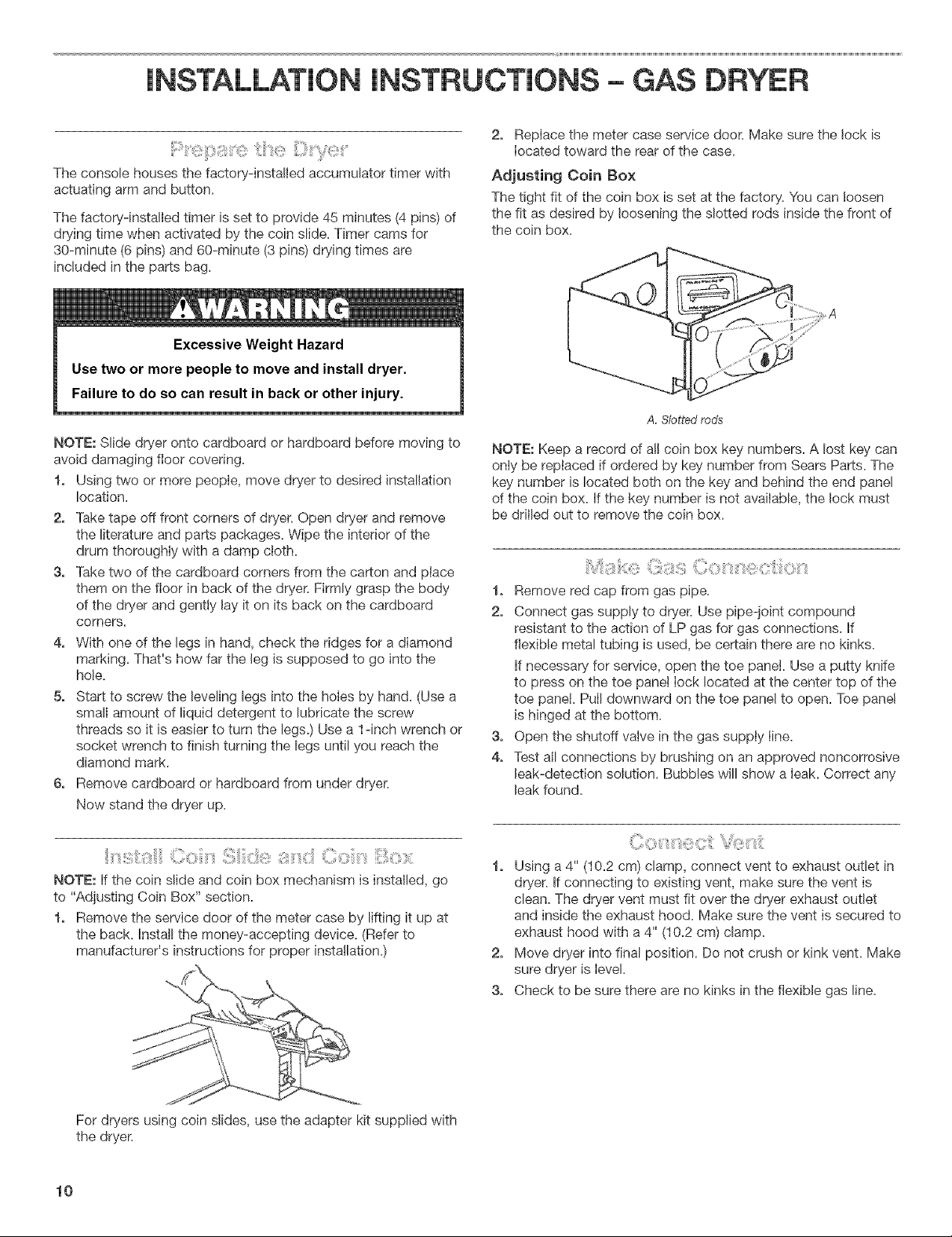
Adjusting Coin Box
The tight fit of the coin box is set at the factory. You can loosen
the fit as desired by loosening the slotted rods inside the front of
the coin box.
A. Slotted rods
NOTE: Keep a record of a!l coin box key numbers. A lost key can
only be replaced if ordered by key number from Sears Parts. The
key number is located both on the key and behind the end panel
of the coin box. If the key number is not available, the lock must
be drilled out to remove the coin box.
1. Remove red cap from gas pipe.
2. Connect gas supply to dryer. Use pipe-joint compound
resistant to the action of LP gas for gas connections. If
flexible metal tubing is used, be certain there are no kinks.
If necessary for service, open the toe panel. Use a putty knife
to press on the toe panel Iock located at the center top of the
toe panel. PulI downward on the toe panel to open. Toe panel
is hinged at the bottom.
3. Open the shutoff valve in the gas supply line.
4. Test all connections by brushing on an approved noncorrosive
leak-detection solution. Bubbles will show a leak. Correct any
leak found.
NOTE: If the coin slide and coin box mechanism is installed, go
to "Adjusting Coin Box" section.
1. Remove the service door of the meter case by lifting it up at
the back. Install the money-accepting device. (Refer to
manufacturer's instructions for proper installation.)
For dryers using coin slides, use the adapter kit supplied with
the dryer.
10
1. Using a 4" (10,2 cm) clamp, connect vent to exhaust outlet in
dryer. If connecting to existing vent, make sure the vent is
clean. The dryer vent must fit over the dryer exhaust outlet
and inside the exhaust hood. Make sure the vent is secured to
exhaust hood with a 4" (10.2 cm) clamp.
2. Move dryer into final position. Do not crush or kink vent. Make
sure dryer is level
3, Check to be sure there are no kinks in the flexible gas line,
Page 11
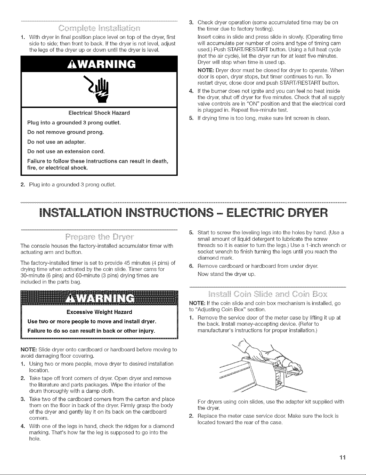
With dryer in final position place level on top of the dryer, first
side to sidel then front to back. if the dryer is not level, adjust
the legs of the dryer up or down until the dryer is level.
Electdcam Shock Hazard
Pmuginto a grounded 3 prong outJet.
Do not remove ground prong,
Do not use an adapter,
Do not use an extension cord.
FaiJure to follow these instructions can resumt in death,
fire, or e_ectricam shock,
2, Plug into a grounded 3 prong outlet.
3, Check dryer operation (some accumulated time may be on
the timer due to factory testing).
insert coins in slide and press slide in slowly. (Operating time
will accumulate per number of coins and type of timing cam
used.) Push START/RESTART button. Using a fulI heat cycle
(not the air cycle), Jetthe dryer run for at least five minutes.
Dryer wJJlstop when time is used up.
NOTE: Dryer door must be closed for dryer to operate. When
door is open, dryer stops, but timer continues to run. To
restart dryer, close door and push START/RESTART button.
4, if the burner does not ignite and you can feel no heat inside
the dryer, shut off dryer for five minutes. Check that all supply
valve controls are in "ON" position and that the electrical cord
is plugged in. Repeat five-minute test.
5, if drying time Jstoo long, make sure Jint screen Jsclean.
iNSTALLATiON iNSTRUCTiONS- ELECTRIC DRYER
The consob houses the factorydnstaHed accumulator timer with
actuating arm and button.
The factory-installed timer is set to provide 45 minutes (4 pins) of
drying time when activated by the coin slide. Timer cams for
30-minute (6 pins) and 60-minute (3 pins) drying times are
included in the parts bag.
NOTE: Slide dryer onto cardboard or hardboard before moving to
avoid damaging floor covering.
1, Using two or more people, move dryer to desired installation
location.
2, Take tape off front corners of dryer. Open dryer and remove
the literature and parts packages. Wipe the interior of the
drum thoroughly with a damp cloth.
3, Take two of the cardboard corners from the carton and place
them on the floor in back of the dryer. Firmly grasp the body
of the dryer and gently Iay it on its back on the cardboard
corners.
4, With one of the legs in hand, check the ridges for a diamond
marking. That's how far the leg is supposed to go into the
hole.
5, Start to screw the leveling legs into the holes by hand. (Use a
small amount of liquid detergent to lubricate the screw
threads so it is easier to turn the legs.) Use a 1-inch wrench or
socket wrench to finish turning the legs until you reach the
diamond mark.
6, Remove cardboard or hardboard from under dryer.
Now stand the dryer up.
NOTE: if the coin slide and coin box mechanism is installed, go
to "Adjusting Coin Box" section.
1, Remove the service door of the meter case by lifting it up at
the back. Install money-accepting device. (Refer to
manufacturer's instructions for proper installation.)
For dryers using coin sJides, use the adapter kit supplied with
the dryer.
Replace the meter case service door. Make sure the lock is
located toward the rear of the case.
11
Page 12
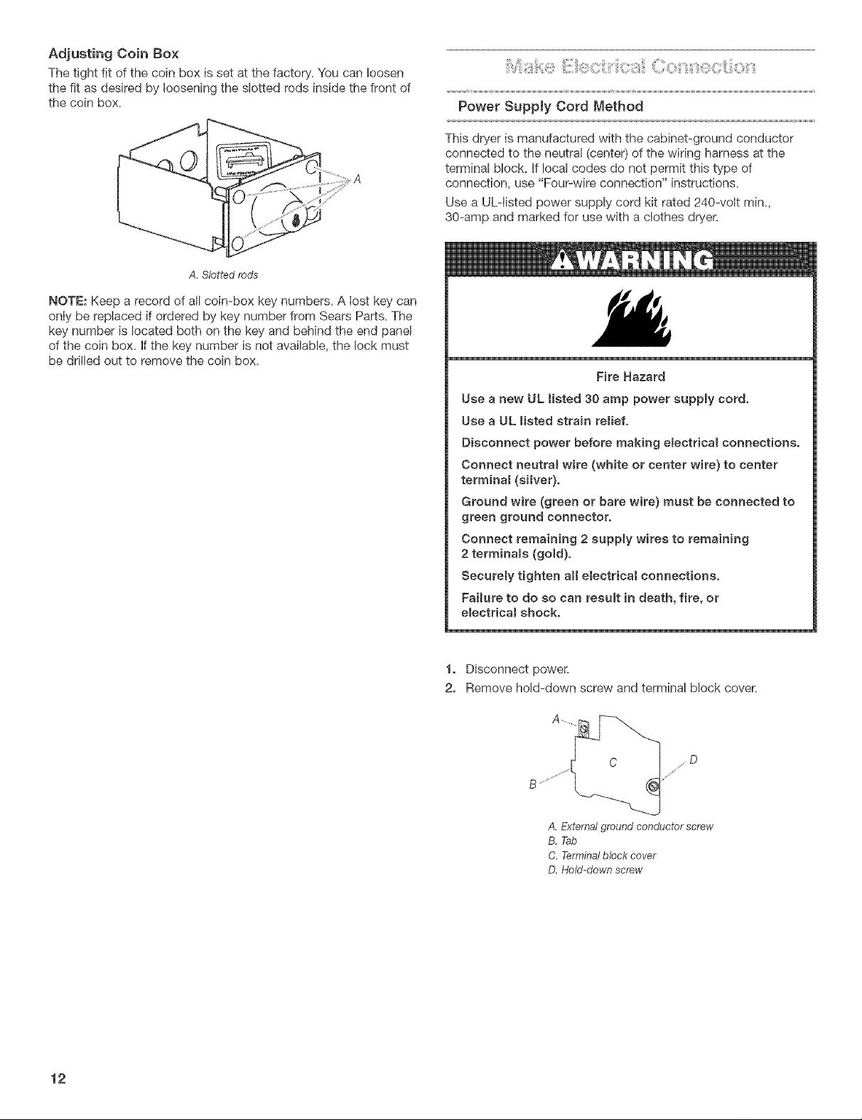
Adjusting Coin Box
The tight fit of the coin box is set at the factory. You can !oosen
the fit as desired by loosening the slotted rods inside the front of
the coin box.
A. Slotted rods
NOTE: Keep a record of all coin-box key numbers. A lost key can
only be replaced if ordered by key number from Sears Parts. The
key number is located both on the key and behind the end panel
of the coin box. If the key number is not available, the lock must
be drilled out to remove the coin box.
Power Supply Cord Method
This dryer is manufactured with the cabinet-ground conductor
connected to the neutral (center) of the wiring harness at the
terminal block. If local codes do not permit this type of
connection, use "Four-wire connection" instructions.
Use a UL-tisted power supply cord kit rated 240-volt min.,
30-amp and marked for use with a clothes dryer.
Fire Hazard
Use a new UL Hsted 30 amp power euppmy cord,
Use a UL listed strain remief.
Disconnect power before making electricam connections.
Connect neutral wire (white or center wire) to center
terminam (sliver).
Ground wire (green or bare wire} must be connected to
green ground connector.
Connect remaining 2 supply wires to remaining
2 terminams (gold),
Securely tighten aH e_ectricam connections.
Failure to do so can resumt in death, fire, or
e_ectdcam shock.
12
1° Disconnect power.
2. Remove hold-down screw and terminal block cover.
A. Extemat ground conductor screw
B. Tab
C. Terminalblock cover
D. Held-down screw
Page 13
3.
Assemble ¾" UL-listed strain relief (UL marking on strain
relief) into the hole below termina! block opening. Tighten
strain relief screws just enough to hold the two clamp
sections together. Install power supply cord through the
strain relief.
A. Strain relief clamp sections
B, Dryer cabinet
C, Strain relief screws
4.
Complete installation following instructions for your type of
electrical connection:
Four-wire (recommended method)
Three-wire (if four-wire is not available)
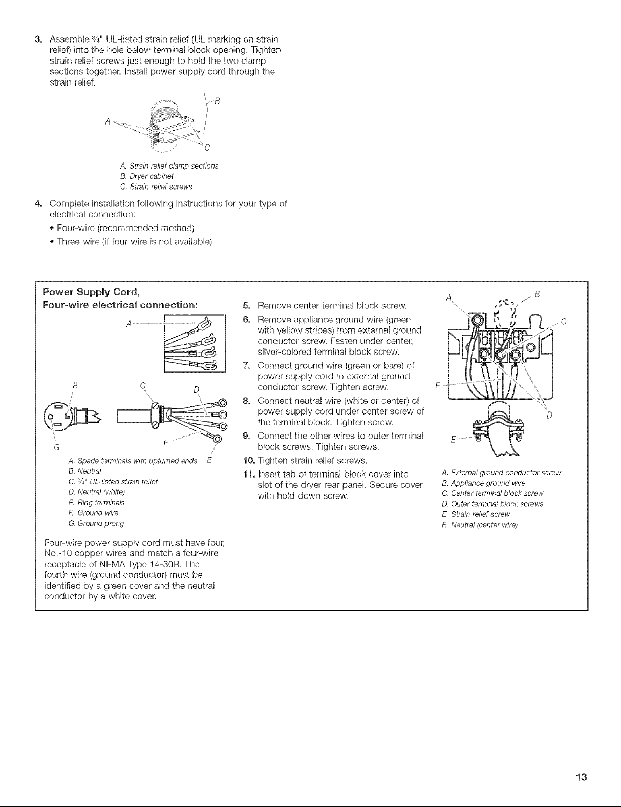
Power Supply Cord,
Four-wire electrical connection:
G
A, Spade terminals with upturned ends E
B.Neutral
C.3/4"UL4isted strain relief
O. Neutral (white)
E. Ring terminals
E Ground wire
G, Ground prong
Four-wire power supply cord must have four,
No.-lO copper wires and match a four-wire
receptacle of NEMA Type 14-30R. The
fourth wire (ground conductor) must be
identified by a green cover and the neutral
conductor by a white cover.
5. Remove center terminal block screw.
6. Remove appliance ground wire (green
with yellow stripes) from external ground
conductor screw. Fasten under center,
silver-colored terminal block screw.
7. Connect ground wire (green or bare) of
power supply cord to external ground
conductor screw. Tighten screw.
8. Connect neutral wire (white or center) of
power supply cord under center screw of
the terminal block. Tighten screw.
9. Connect the other wires to outer terminal
block screws. Tighten screws.
10. Tighten strain relief screws.
11. Insert tab of terminal block cover into
slot of the dryer rear panel. Secure cover
with hold-down screw.
A ....B
_z
I c
i_
E ............ __
A, External ground conductor screw
B. Appliance ground wire
C. Center terminal block screw
D. Outer terminal block screws
E. Strain relief screw
E Neutral (center wire)
D
13
Page 14

Power Supply Cord, Use this method where local cedes permit connecting
Three-wire electrical connection_ cabinet-ground conductor to neutral w{re: A
5, Loosen or remove center terminal block
screw.
6, Connect the neutral wire (white or center)
of power supply cord to the center, silver-
colored terminal screw of the terminal
block. Tighten screw.
E
7, Connect the other wires to outer terminal
block screws. Tighten screws.
8, Tighten strain relief screws.
9, insert tab of terminal block cover into slot
of dryer rear panel. Secure cover with
hold-down screw.
This blade connected to B
A. Spade terminals with upturned ends
B. Ring terminals
C.Neutral (white or center)
D. 3/4"UL-listed strain relief
E. Neutral
Three-wire power supply cord must
have three, No.-10 copper wires and
match a three-wire receptacle of NEMA
Type 10-30R.
Use this method where local codes do not permit
connecting cabinet-ground conductor to neutral wire:
5, Remove center terminal block screw.
6, Remove the appliance ground wire (green
with yellow stripes) from the external
ground conductor screw. Connect
appliance ground wire and the neutral
wire (white or center) of the power supply
A. External ground conductor screw
B. Center terminal block screw
C, Outer terminal block screws
D, Strain relief screw
E. Neutral (center wire)
cord under the center, silver-colored
terminal block screw. Tighten screw.
7, Connect the other wires to outer terminal
block screws. Tighten screws.
8, Tighten strain relief screws.
9, Insert tab of terminal block cover into slot
of dryer rear panel. Secure cover with
hold-down screw.
F ..........'_ E
10, After reattaching the terminal cover,
connect a separate copper ground wire
from the external ground conductor screw
to an adequate ground.
If codes permit and a separate ground wire is
used, it is recommended that a qualified
electrician determine that the ground path is
adequate.
A. Separate copper ground wire
B, External ground conductor screw
C, Appliance ground wire
D. Center terminal block screw
E, Outer terminal block screws
F. Strain relief screw
G. Neutral (center wire)
_ C
D
14
Page 15

DirectWireMethod
Fire Hazard
Use 10 gauge soJid copper wire.
Use a UL misted strain relief.
Disconnect power before making emectrica_ connections.
Connect neutral wire (white or center wire) to center
terminal (simver).
Ground wire (green or bare wire) must be connected to
green ground connector.
Connect remaining 2 suppmy wires to remaining
2 termina_s (go_d).
SecureSy tighten aH eBectrical connections.
Failure to do so can result in death, fire, or
emectrical shock.
1, Disconnect power.
2, Remove hold-down screw and terminal block cover.
sO
/"
A. External ground conductor screw
B. Tab
C, Terrninalblock cover
D, Hold-down screw
Install ¾" conduit connector into the hole below terminal
block opening, Connect flexible metallic conduit and tighten
connector screw, Install direct wire cable through flexible
metallic conduit.
J
......B
\
A, Conduit connector
B. Dryer cabinet
C, Connector screw
Direct wire cable must match power supply (4-wire or 3-wire) and
be:
[] Flexible armored cable or nonmetallic sheathed copper cable
(with ground wire), protected with flexible metallic conduit. AII
current-carrying wires must be insulated,
[] 10-gauge solid copper wire (do not use aluminum),
[] At least 5 ft. (1.52 m) long.
Direct Wire,
Four=wire electrical connection:
31f2' (8,9 cm) _1
to
disconnect
box
Shapeends
ofwires into
ahook,
A, 3/4"conduit connector
B. Neutral (white or center)
C, Ground wire (green or bare)
D, lO-gauge, 3 wire with ground wire in
ofwires |_
stripped of |
insulation I_
5" (12.7 cm)
Strip 5" (12_7 cm) of outer covering
from end of cable, Leave bare ground
wire at 5" (12,7 cm), Cut 11f/' (3.8 cm)
from 3 remaining wires, Strip
insulationback1"(2.5cm),
flexible metallic conduit
I
5, Remove center terminal block screw.
6, Remove appliance ground wire (green
with yellow stripes) from external ground
conductor screw. Fasten under center,
silver-colored terminal block screw,
7, Connect the ground wire (green or bare)
of the direct wire cable to the external
ground conductor screw. Tighten screw,
8, Place the hooked end of the neutra! wire
(white or center) of direct wire cable
under the center screw of terminal block
(hook facing right). Squeeze hooked end
together, Tighten screw,
9, Place the hooked ends of the other
direct wire cable wires under the outer
terminal block screws (hook facing right),
Squeeze hooked ends together. Tighten
SCreWS.
10, Insert tab of terminal block cover into
slot of dryer rear panel Secure cover
with hold-down screw.
Complete installation following instructions for your type of
electrical connection:
®Four-wire (recommended method)
Three-wire (iffour-wire is not available)
A....... _._'-.....
.fj C
........ .....................'
D
A. External ground conductor screw
B, Appliance ground wire
C,Center terminal block screw
D. Outer terminal block screws
E. Neutral (center wire)
15
Page 16

Direct Wire,
Three=wire electrical connection:
Three wire with ground wire: Green or bare
wire cut short, Wire is not used, Dryer is
grounded throu( h neutral conductor.
A 1"(2,5cm)--
to strippedof
disconnect insulation
box
of wires into
_ Shapeends
a hook.
A. :¼"conduit connector
B. Neutral (white or center)
C. lO-gauge, 3 wire with ground wire in
flexible metallic conduit
ofwires
Strip 3V2" (8_9 cm) of outer
covering from end of cable. Strip
insulation back 1" (2,5 cm). If using
3 wire cable with ground wire, cut
bare wire even with outer covering,
H
(8,9 cm)
Use this method where mocal codes permit
connecting cabinet-ground conductor to
neutral wire:
5, Loosen or remove center terminal block
screw.
6, Place the hooked end of the neutral wire
(white or center) of direct wire cable
under the center screw of the terminal
block (hook facing right). Squeeze
hooked end together. Tighten screw.
7, Place the hooked ends of the other
direct wire cable wires under the outer
terminal block screws (hook facing right).
Squeeze hooked ends together. Tighten
screws.
8, Insert tab of terminal block cover into
slot of dryer rear panel. Secure cover
with hold-down screw.
Use this method where mocal codes do
not permit connecting cabinet-ground
conductor to neutram wire:
5, Remove center terminal block screw.
6, Remove the appliance ground wire (green
with yellow stripes) from the external
ground conductor screw. Connect
appliance ground wire and the neutral wire
(white or center) of the direct wire cable
under the center, silver-colored terminal
block screw. Tighten screw.
7, Connect the other wires to outer terminal
block screws. Tighten screws.
8, Insert tab of terminal block cover into slot
of dryer rear panel. Secure cover with hold-
down screw.
9, After reattaching the terminal cover,
connect a separate copper ground wire
from the external ground connector screw
to an adequate ground.
If codes permit and a separate ground wire is
used, it is recommended that a qualified
electrician determine that the ground path is
adequate.
"C
A. External ground conductor screw
B. Center terminal block screw
C. Outer terminal block screws
D. Neutral (center wire)
A. Separate copper ground wire
B. External ground conductor screw
C. Appliance ground wire
D. Center terminal block screw
E. Outer terminal block screws
F. Neutral (center wire)
Using a 4" (10.2 cm) clamp, connect vent to exhaust outlet in
dryer. If connecting to existing vent, make sure the vent is
clean. The dryer vent must fit over the dryer exhaust outlet
and inside the exhaust hood. Make sure the vent is secured to
exhaust hood with a 4" (10.2 cm) clamp.
2,
Move dryer into final _osition. Do not crush or kink vent. Make
sure dryer is level
With dryer in final position place level on top of the dryer, first
side to side; then front to back. If the dryer is not level, adjust
the legs of the dryer up or down until the dryer is level.
16
2, Plug in dryer or reconnect power.
3, Check dryer operation (some accumulated time may be on
the timer due to factory testing).
Insert coins in slide and press slide in slowly. (Operating time
will accumulate per number of coins and type of timing cam
used.) Push START/RESTART button. Using a full heat cycle
(not the air cycle), let the dryer run for at least five minutes.
Dryer will stop when time is used up.
NOTE: Dryer door must be closed for dryer to operate. When
door is open, dryer stops, but timer continues to run. To
restart dryer, close door and push START/RESTART button.
4, If drying time is too long, make sure lint screen is clean.
5, Now start the dryer and allow it to complete a full heat cycle
(not air cycle) to make sure it is working properly.
Page 17

COIN BOX OPTIONS
t:O ;11710¸--.¸elf'
Electrical Shock Hazard
Disconnect power before servicing,
Replace all parts and panels before operating.
Failure to do so can result }n death or electr}cal shock.
You can install the 30-minute or 60-minute timing cam (shipped
with dryer) as follows:
1° Unplug dryer or disconnect power.
2, Unlock meter case.
3, Turn the timing cam by hand until the V-shaped notch lines up
below the ratchet tooth.
NOTE: For any other type of money-accepting device, please see
the manufacturer's instructions to change vend price.
Electricam Shock Hazard
Disconnect power before servicing,
Replace all parts and panels before operating.
Failure to do so can result in death or electdcam shock.
1° Unplug dryer or disconnect power,
NOTE: Place all screws and other items removed from coin slide
assembly on a cloth so they will not get lost,
2, Remove service door from meter case,
3, Remove chute bolt from slide mechanism and remove slide
mechanism from meter case.
B. Timing cam
C. 77metShaft
O. Drive lug
E, V-shaped notch
4, Insert a narrow, fiat-blade screwdriver under the timing cam
near the timer shaft. Gently lift cam straight up and off shaft
making sure that the V-shaped notch clears the ratchet tooth,
5, Place new cam (hub side down) over clock shaft. Line up flat
side of shaft with flat side of cam hole. Check that drive lug is
in place,
6, Turn cam until V-shaped notch lines up with ratchet tooth,
7° Press cam down in place on motor shaft. Make sure that
V-shaped notch clears the ratchet tooth,
8, Close and lock the meter case,
9, Plug in dryer or reconnect power.
A. Chute bolt
B. Coin slide mechanism
C. Access
4_
Unhook and remove slide return spring.
5,
Place coin(s) in coin slot(s) and >ash forward all the way,
Remove 2 screws securing buffer and detach buffer.
A i i
I
(
h *¢- _ i !-_'}i:-/L : ....I
= I " } /I _: if ;;_ z
,j i _,
A,Buffer
17
Page 18

6,
Turn coin chute upside down and set new vend price by
adding or removing the appropriate block-out keys and/or
dime inserts according to the following Table of Vend Prices.
TABLE OF VEND PRICES
VEND comN SLOTS
PR|CE I _ 3 4 _ 6 7 8
o ||||||||
lO¢ o|||||||
25¢ ||D|||||
35co|D|||||
50¢ ||OD||||
6o®o|OD||||
75¢ ||0B0|||
85¢ 8|0B0|||
÷1.oo ||OBOB||
• 1.1o o|ODOD||
•I.e5 IDODODil
$I.35 0|ODODO|
$1.5o |DODODO|
•1.so0DODODO|
_1.7s |8080808
•I.S5 oBOBOBOB
_e.oo|BOBOBOB
NOTES:
[] Black slots are closed off by Mock-out key, To remove block-
out keys, pull straight up,
[] Be sure Mock-out keys and/or dime inserts are seated
properly and ratchet dog is in place with its spnng connected,
Be sure the proper coin sizing block is in place.
Part # 20-3007 for up to 7 quarters and 1 dime
Part # 20-3006 for up to 8 quarters and 0 dimes
[] Unless otherwise ordered, a[I coin chutes are supplied with
Part # 20-3006 in place,
7, Reassemble buffer to bottom of c[o[n slide and secure with 2
screws.
8, Pu[I slide back to original position and reattach slide return
spring,
9, Reinstall slide mechanism into meter case, replace chute bolt.
10, Reptace service door.
11, Plug in dryer or reconnect power,
NOTE: Refer to the product information sheet provided with the
coin box for additional information.
18
Page 19

Maintenance instructions:
mClean Iint screen after each cycle.
mRemoving accumulated lint:
mFrom inside the dryer cabinet:
Lint should be removed every 1 or 2 years or more often,
depending on dryer usage. Cleaning should be done by a
qualified person.
mFrom the exhaust vent:
Lint should be removed every 2 years, or more often,
depending on dryer usage.
If dryer does not operate check the following:
mElectric supply is connected.
mCircuit breakers are not tripped or fuses are not blown.
mDoor is closed.
mControls are set in a running or "ON" position.
mSTART button has been pushed firmly.
mFor gas dryers, check that gas supply shutoff valves are set in
open position.
if you need assistance:
For Sears warranty information or to contact a Sears Service
Center, call I=800=4=MY=HOME _ (1=800=469-4663).
if you need SERVICE or PARTS for your Kenmore coin-
operated washer:
When requesting service, be ready to give the model number,
serial number (located in the dryer door well) and date of
purchase. Record on front cover.
SEARS COMMERCIAL DRYER WARRANTY
Models 66152 and 76152
Limited 2=Year Warranty on
lViechanical and Electrical Parts
For two years from the date of purchase, when the dryer is
installed in accordance with the instructions in the hstallation
Instructions, Sears will furnish replacement parts for all defective
mechanical or electrical parts, including coin boxes and chute
assemblies. You will be charged for labor.
Warranty Restriction
If the dryer is vented with nonmetallic, flexible plastic venting, this
warranty is void. See the installation section of the Installation
Instructions for complete exhaust requirements.
Warranty Service
Warranty service is available by contacting the nearest Sears
Service Center in the United States=
This warranty applies only while this product is used in the United
States=
This warranty gives you specific legal rights, and you may have
other rights which vary from state to state.
Use the space below to record the model number and serial
number of your new Sears Commercial dryer.
Model number
Serial number
Date of Purchase
NOTE: Keep this warranty and your Sears salescheck (receipt) in
a safe place for future reference.
Sears, Roebuck and Co., Dept. 817WA,
Hoffman Estates, IL 60179
For Sears warranty information or to contact a Sears Service
Center, call 1-800-4-MY-HOME ®(1-800-469-466%
19
Page 20

Your Home
For repair-in your home-of aHmajor brand appliances,
lawn and garden equipment, or heating and cooling systems,
nomatterwhomadeit,nomatterwhosoldit!
For the replacement parts, accessories and
owner's manuals that you need to do-it-yourself.
For Sears professional installation of home appliances
and items like garage door openers and water heaters.
1-8oo-4-M¥-.oM,=®
Ca,any_,_e,dayorn_ght(U.S.A.andCanada)
,,,_,,,,.soa,._,.oo,.,.,_,.,,,.,ea_,.oa
For repair of carry-in items likevacuums, lawn equipment,
and electronics, cali or go on°linefor the Jocation of your nearest
SearsParts8,R<,_i_Ceote_.
1o800o488o1222
Ca,anyt_mo,dayorn_ght<U.S.A.on_yt
www.ooo,o.oom
TO purchase a protection agreement (U.S.A.)
or maintenance agreement (Canada)on a product serviced by Sears:
1-800-827-6655 (U.S.A.) 1-800-361-6665 (Canada)
Para pedir servicio de reparaci6n Au Canada pour service en frangais:
a domicilio, y para ordenar piezas: 1.800.LE.FOYERMC
1"888°SU°HOGARSM (1-800-533-6937)
(1-888-784-6427) www.sears.ca
@ Registered Trademark / TMTrademark / SM Service Mark of Sears, Roebuck and Co.,
@Marca Registrada / TM Marca de comercio / SM Marca de Servicio de Sears, Roebuck and Co,, 05/2005
8575078 ¢) Marque d@osee / TMMarque de commerce / SMMarque de service de Sears, Roebuck and Co.,
_:; Sears, Roebuck and Co, Imprim_, aux E,-U.
used under licensee by Sears Canada,
usada bajo licencia de Sears Canada. Printed in U,S.A.
en vertu diun porieur de licence par Sears Canada, Impreso en EE, UU.
 Loading...