

Kenmore 11064932200, 11064924200, 11064922200, 11064912200, 11064902200 Owner’s Manual
...
Owner's Manual and
Installation Instructions
29-Inch Wide
ELECTRIC DRYERS
IMPORTANT:
Read and follow all safety
and operating instructions
before first use of this product.
Sears, Roebuck and Co., Hoffman Estates, IL 60179 U.S.A.
www.sears.com
3979089B PRINTED IN U.S.A. 12/01
BEFORE USING YOUR NEW DRYER
KENMORE DRYER WARRANTY
DRYER SAFETY 4
INSTALLATION INSTRUCTIONS 6
DRYER USE 19
LAUNDRYTIPS
DRYER CARE 27
TROUBLESHOOTING 30
WE SERVICE WHAT WE SELL 32
Please read this manual. It will help
you install and operate your new
Kenmore dryer in the most economical
way.
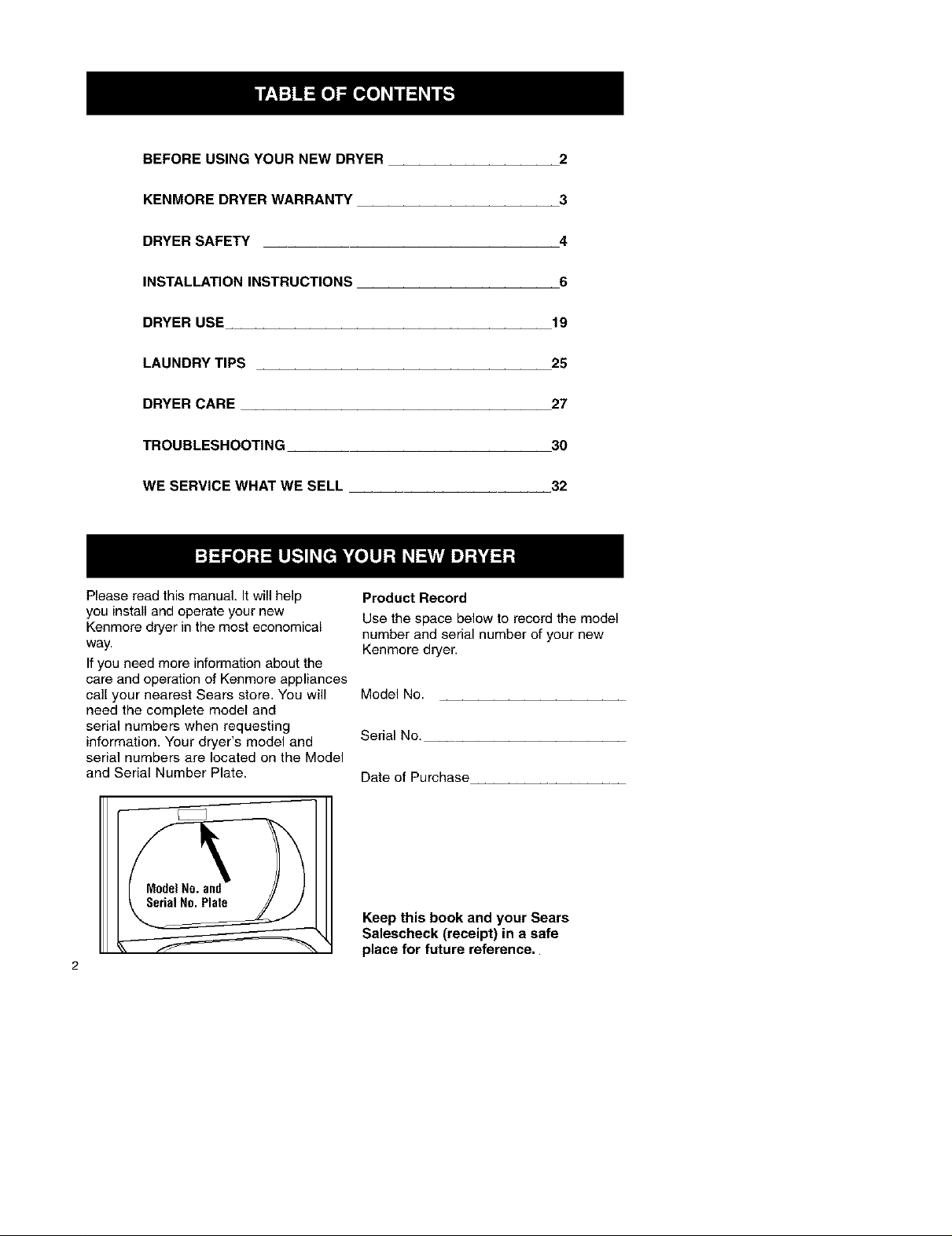
Ifyou need more information about the
care and operation of Kenmore appliances
call your nearest Sears store. You will
need the complete model and
serial numbers when requesting
information. Your dryer's model and
serial numbers are located on the Model
and Serial Number Plate.
25
Product Record
Use the space below to record the model
number and serial number of your new
Kenmore dryer.
Model No.
Serial No.
Date of Purchase
Model No. and
Serial No. Plate
Keep this book and your Sears
Salescheck (receipt) in a safe
place for future reference.
2
Full One Year Warranty on
Mechanical and Electrical Parts
For one year from the date of purchase,
if this dryer is installed and operated
according to the instructions in this
manual, Sears will repair or replace any
of its mechanical or electrical parts if they
are defective in material or workmanship.
NOTE: Exhausting your dryer with
a plastic vent may void this warranty.
See "Installation Instructions" for the
complete exhaust requirements
for this dryer.
Warranty Restriction
If the dryer is subjected to other than
private family use, all warranty coverage is
effective for only 90 days.
Warranty Service
Warranty service is available by contacting
your nearest Sears Service Center in the
United States.
This warranty applies only while thisdryer
is in use in the United States.
This warranty gives you specific legal
rights, and you may also have other rights
which vary from state to state.
Sears, Roebuck and Co., Dept. 817WA,
Hoffman Estates, IL 60179,
For Sears Warranty information or 1ocontact a Sears
Service Cenler, please reference the service numbers
located on the back page of lhis manual.
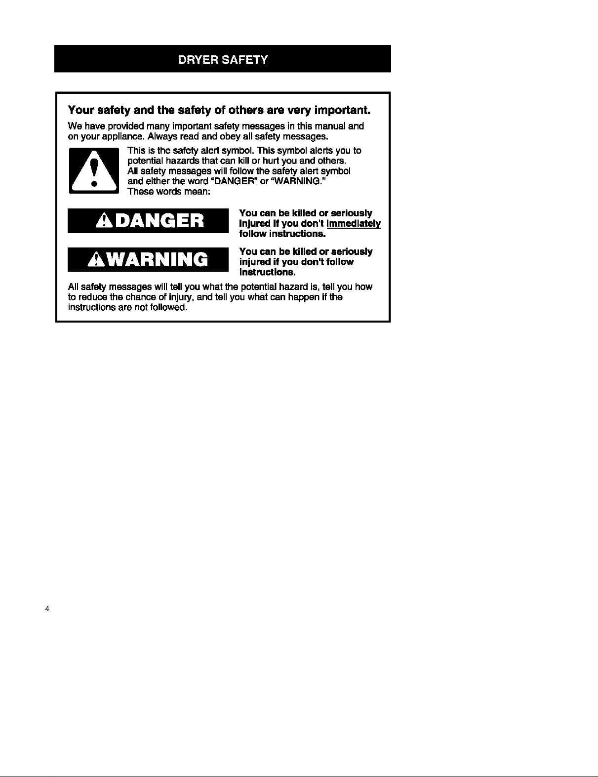
Your safety and the safety of others are very important.
We have providedmany importantsafety messages inthis manual and
on your appliance. Always read and obey all safetymessages.
This is the safety alert symbol.This symbolalerts youto
potentialhazardsthatcan killor hurtyou and others.
All safetymessages will followthe safety alert symbol
and eitherthe word "DANGER" or 'WARNING."
These words mean:
You can be killed or seriously
injured if you don't immediately
follow instructions.
You can be killed or seriously
injured if you don't follow
instructions.
All safetymessages will tellyou what the potentialhazard is, tell you how
to reducethe chance of injury,and tell you what can happen ifthe
instructionsare notfollowed.
4
IMPORTANT SAFETY INSTRUCTIONS
WARNING : To reduce the risk of fire, electric shock, or injury to persons
when using the dryer, follow basic precautions, including the following:
• Read all instructions before using
the dryer.
• Do not place items exposed to cook-
ing oils in your dryer. Items contami-
nated with cooking oils may contribute
to a chemical reaction that could
cause a load to catch fire.
• Do not dry articles that have been pre-
viously cleaned in, washed in, soaked
in, or spotted with gasoline, dry-
cleaning solvents, other flammable, or
explosive substances as they give off
vapors that could ignite or explode.
• Do not allow children to play on or in
the dryer. Close supervision of
children is necessary when the dryer
is used near children.
• Before the dryer is removed from
service or discarded, remove the door
to the drying compartment.
• Do not reach into the dryer if the drum
is moving.
• Do not install or store the dryer where
it will be exposed to the weather.
• Do not tamper with controls.
• Do not repair or replace any part of
the dryer or attempt any servicing
unless specifically recommended in
this Owner _ Manual or in
published user-repair instructions
that you understand and have the
skills to carry out.
• Do not use fabric softeners or
products to eliminate static unless
recommended by the manufacturer
of the fabric softener or product.
• Do not use heat to dry articles
containing foam rubber or similarly
textured rubber-like materials.
• Clean lint screen before or after
each load.
• Keep area around the exhaust
opening and adjacent surrounding
areas free from the accumulation
of lint, dust, and dirt.
• The interior of the dryer and
exhaust vent should be cleaned
periodically by qualified service
personnel.
• See the "INSTALLATION
INSTRUCTIONS" section for
grounding requirements.
SAVE THESE INSTRUCTIONS
Tools and Parts Location Requirements
Check that you have everything neces-
sary for correct installation. Proper
installation is your responsibility.
• flat-blade screwdriver
• adjustable wrench that opens to 1 in.
or hex-head socket wrench (for
adjusting dryer feet)
level
wire stripper (direct wire installations)
#2 Phillips screwdriver
safety glasses
duct tape
caulking gun and compound (for
installing new exhaust vent)
• gloves
• tin snips (new vent installations)
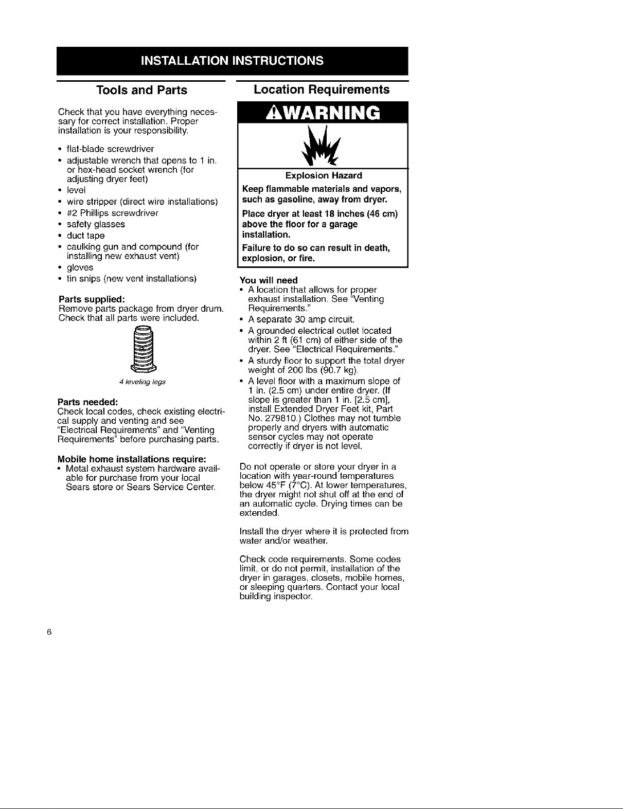
Parts supplied:
Remove parts package from dryer drum.
Check that all parts were included.
4 leveling legs
Parts needed:
Check local codes, check existing electri-
cal supply and venting and see
"Electrical Requirements" and "Venting
Requirements" before purchasing parts.
Mobile home installations require:
• Metal exhaust system hardware avail-
able for purchase from your local
Sears store or Sears Service Center.
Explosion Hazard
Keep flammable materials and vapors,
such as gasoline, away from dryer.
Place dryer at least 18 inches (46 cm)
above the floor for a garage
installation.
Failure to do so can result in death,
explosion, or fire,
You will need
• A location that allows for proper
exhaust installation. See "Venting
Requirements."
• A separate 30 amp circuit.
• A grounded electrical outlet located
within 2 ft (61 cm) of either side of the
dryer. See "Electrical Requirements."
• A sturdy floor to support the total dryer
weight of 200 Ibs (90.7 kg).
• A level floor with a maximum slope of
1 in. (2.5 cm) under entire dryer. (If
slope is greater than 1 in. [2.5 cm],
install Extended Dryer Feet kit, Part
No. 279810.) Clothes may not tumble
properly and dryers with automatic
sensor cycles may not operate
correctly if dryer is not level.
Do not operate or store your dryer in a
location with year-round temperatures
below 45°F (7°C). At lower temperatures,
the dryer might not shut off at the end of
an automatic cycle. Drying times can be
extended.
Install the dryer where it is protected from
water and/or weather.
Check code requirements. Some codes
limit, or do not permit, installation of the
dryer in garages, closets, mobile homes,
or sleeping quarters. Contact your local
building inspector.
6
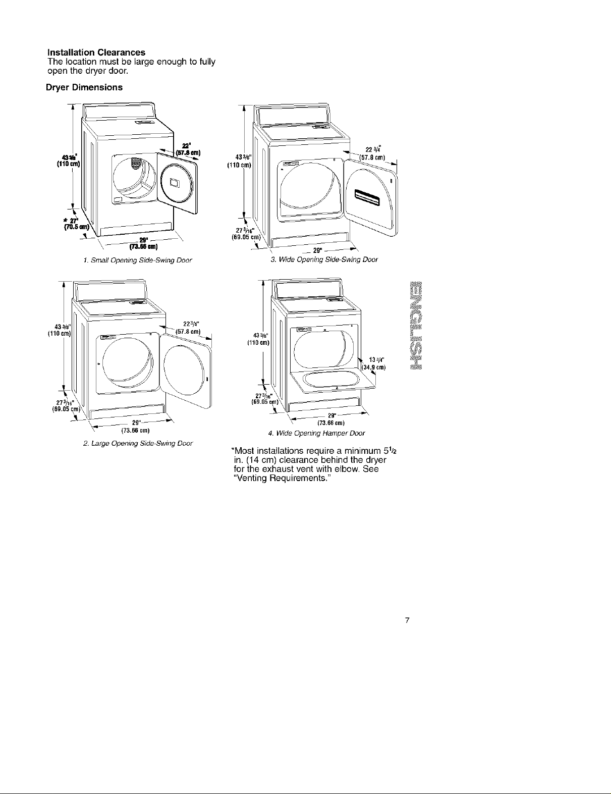
Installation Clearances
The location must be large enough to fully
open the dryer door.
Dryer Dimensions
1 Small Opening Side-Swing Doer
22_/#*
(110
273/1_"
(69,05 c
\ __ 29"_
3. Wide Opening Side-Swing Doer
\
\ 29,,_
_7(73.66 era)
2. Large Opening Side-Swing Door
*Most installations require a minimum 51_2
in. (14 cm) clearance behind the dryer
for the exhaust vent with elbow. See
"Venting Requirements."

Minimum installation spacing for
recessed area or closet installation
The dimensions shown following are for
the minimum spacing allowed.
• Additional spacing should be
considered for ease of installation and
servicing.
• Additional clearances might be
required for wall, door and floor
moldings.
• Additional spacing of 1 in. (2.5 cm) on
all sides of the dryer is recommended
to reduce noise transfer.
• For closet installation, with a door,
minimum ventilation openings in the
top and bottom of the door are
required. Louvered doors with
equivalent ventilation openings are
acceptable.
• Companion appliance spacing should
also be considered.
o,o
(46.7m_)
JE
m
m
t"
(_)
1310=rn2)-
1155crM) _-3"
Mobile Home-Additional Installation
Requirements
This dryer is suitable for mobile home
installations. The installation must con-
form to the Manufactured Home
Construction and Safety Standard, Title
24 CFR, Part 3280 (formerly the Federal
Standard for Mobile Home Construction
and Safety, Title 24, HUD Part 280)
8
_,5 t_11) _,5 crn)(69 O5 cm) (14 cm)
1 2
_3"
48 ,*z
24,,z
3 _.e_)
1 RecessedArea
2 Side view - closet or confined
area
3 Closet door with vents
Mobile home installations require:
• Metal exhaust system hardware which
is available for purchase from your
local Sears store or Sears Service
Center.
• Special previsions must be made in
mobile homes to introduce outside air
into the dryer. The opening (such as a
nearby window) should be at least
twice as large as the dryer exhaust
opening
Electrical Requirements
It is your responsibility:
• To contact a qualified electrical
installer.
• To be sure that the electrical connec-
tion is adequate and in conformance
with the National Electrical Code,
ANSl/NFPA 70-latest edition and all
local codes and ordinances.
A copy of the above code standards
can be obtained from: National Fire
Protection Association, Batterymamh
Park, Quincy, MA 02269.
• To supply the required 3 or 4 wire, sin-
gle phase, 120/240-volt, 60-Hz., AC-
only electrical supply (or 3 or 4 wire,
120/208-volt electrical supply, if speci-
fied on the serial/rating plate) on a
separate 30-amp circuit, fused on both
sides of the line. A time-delay fuse or
circuit breaker is recommended.
Connect to an individual branch circuit.
Do not have a fuse in the neutral or
grounding circuit.
• Do not use an extension cord.
• Ifcodes permit and a separate ground
wire is used, it is recommended that a
qualified electrician determine that the
ground path is adequate.
Electrical Connection
To properly install your dryer, you must
determine the type of electrical connec-
tion you will be using and follow the
instructions provided for it here.
• If local codes do not permit the con-
nection of a cabinet ground connector
to the neutral wire, see "Optional 3-wire
connection" section.
• This dryer is manufactured with a 3-
wire, cabinet-ground conductor con-
nected to the NEUTRAL (white or cen-
ter wire) of the wiring harness at the
terminal block.
• Use a 4-wire conductor cord when the
dryer is installed in a mobile home or
an area where local codes do not per-
mit grounding through the neutral.
If using a power supply cord:
Use a UL approved power supply cord kit
marked for use with clothes dryers, the
kit should contain:
• A UL approved 30 amp power supply
cord, rated 120/240 volt minimum. The
cord should be type SRD or SRDT and
be at least 4 ft (1.22 m) long. The wires
that connect to the dryer must end in
ring terminals or spade terminals with
upturned ends.
• A UL approved strain relief.
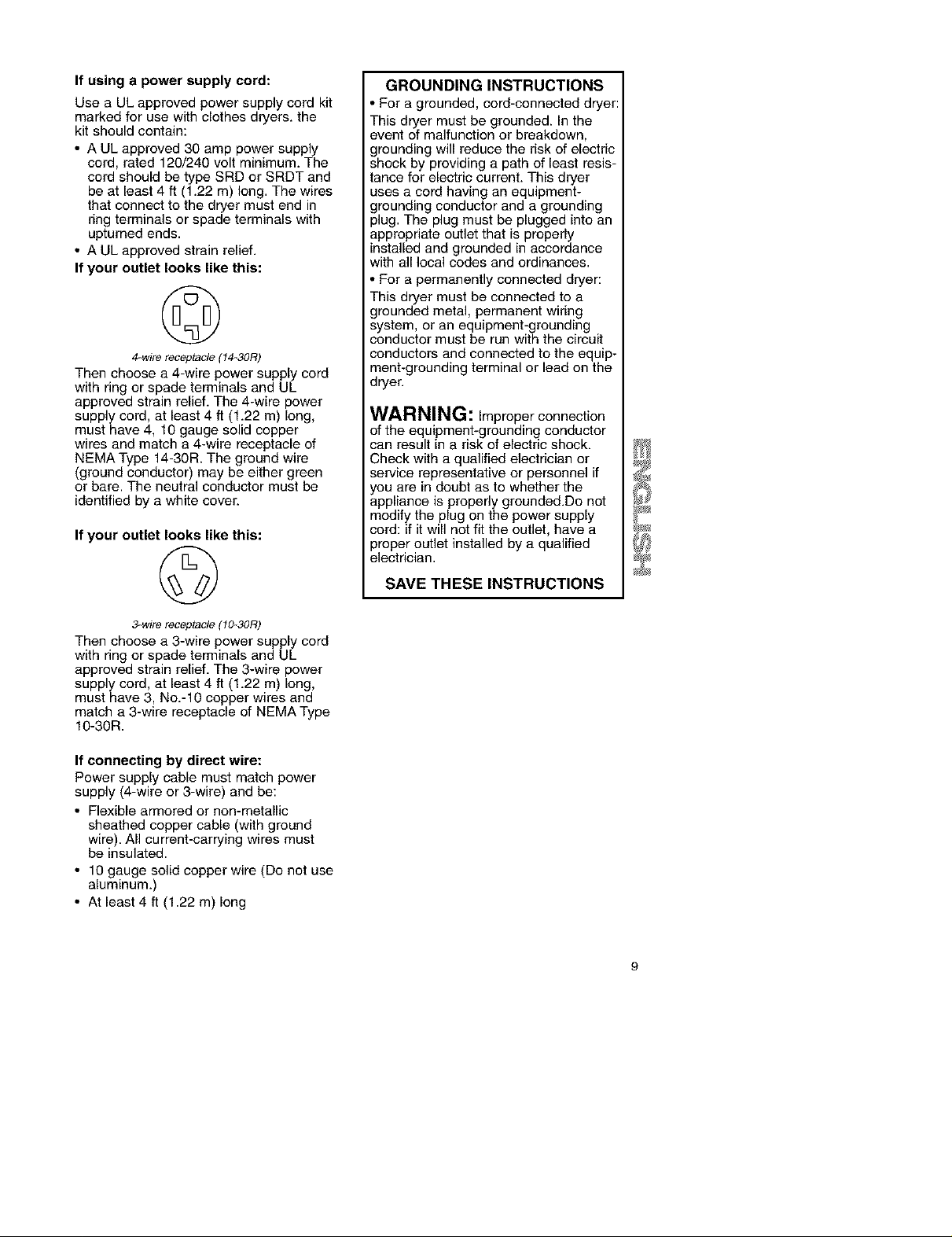
If your outlet looks like this:
©
4_wire receptacle (14_30R)
Then choose a 4-wire power supply cord
with ring or spade terminals and UL
approved strain relief. The 4-wire power
supply cord, at least 4 ft (1.22 m) long,
must have 4, 10 gauge solid copper
wires and match a 4-wire receptacle of
NEMA Type 14-30R. The ground wire
(ground conductor) may be either green
or bare. The neutral conductor must be
identified by a white cover.
If your outlet looks like this:
©
GROUNDING INSTRUCTIONS
• For a grounded, cord-connected dryer:
This dryer must be grounded. In the
event of malfunction or breakdown,
grounding will reduce the risk of electric
shock by providing a path of least resis-
tance for electric current. This dryer
uses a cord having an equipment-
grounding conductor and a grounding
plug. The plug must be plugged into an
appropriate outlet that is properly
installed and grounded in accordance
with all local codes and ordinances.
• For a permanently connected dryer:
This dryer must be connected to a
grounded metal, permanent wiring
system, or an equipment-grounding
conductor must be run with the circuit
conductors and connected to the equip-
ment-grounding terminal or lead on the
dryer.
WARNING: Improper connection
of the equipment-grounding conductor
can result in a risk of electric shock.
Check with a qualified electrician or
service representative or personnel if
you are in doubt as to whether the
appliance is properly grounded.Do not
modify the plug on the power supply
cord: if it will not fit the outlet, have a
proper outlet installed by a qualified
electrician.
SAVE THESE INSTRUCTIONS
3_wire receptacle (10_30R)
Then choose a 3-wire power supply cord
with ring or spade terminals and UL
approved strain relief. The 3-wire power
supply cord, at least 4 ft (1.22 m) long,
must have 3, No.-10 copper wires and
match a 3-wire receptacle of NEMA Type
10-30R.
If connecting by direct wire:
Power supply cable must match power
supply (4-wire or 3-wire) and be:
• Flexible armored or non-metallic
sheathed copper cable (with ground
wire). All current-carrying wires must
be insulated.
• 10 gauge solid copper wire (Do not use
aluminum.)
• At least 4 ft (1.22 m) long

Power Supply Cord
Electrical Connection
Direct Wire
Fire Hazard
Use a new UL approved 30 amp
power supply cord.
Use a UL approved strain relief.
Disconnect power before making
electrical connections.
Connect neutral wire (white or center
wire) to center terminal (silver).
Ground wire (green or bare wire)
must be connected to green ground
connector.
Connect remaining 2 supply wires to
remaining 2 terminals (gold).
Securely tighten all electrical
connections.
Failure to do so can result in death,
fire, or electrical shock.
1. Disconnect power.
2. Remove the hold-down screw and
terminal block cover.
! 2
Fire Hazard
Use 10 gauge solid copper wire.
Use a UL approved strain relief.
Disconnect power before making
electrical connections.
Connect neutral wire (white or center
wire) to center terminal (silver).
Ground wire (green or bare wire) must
be connected to green ground
connector.
Connect remaining 2 supply wires
to remaining 2 terminals (gold).
Securely tighten all electrical
connections.
Failure to do so can result in death,
fire, or electrical shock.
3,
Assemble a 3/4in. (1.9 cm) UL
approved strain relief (UL marking on
strain relief) into the hole below the
terminal block opening. Tighten strain
relief screws just enough to hold the
two clamp sections together. Put
power supply cord through the strain
relief. The strain relief should have a
tight fit with the dryer cabinet and be
in a horizontal position.
Terminal block cover
External ground connector
Center, silver-colored terminal_block
screw
4. Hold_down screw location
E Neutral grounding wire (green/yellow)
6. Hole below terminal block opening
10
instructions for your type of electrical
connection:
4-wire (recommended)
3-wire (if 4-wire is not available)
4. Now complete installation following
 Loading...