

Kenmore 11072182100, 11062182103, 11062182102, 11062182100 Owner’s Manual
8E, q8
OWNER'S MANUAL
TABLE OF CONTENTS
Dryer Safety ............................................................ 2
Installation Instructions ......................................... 3
Electrical requirements ........................................ 4
Gas requirements .............................................. 10
Exhaust requirements ........................................ 12
Recessed area/closet installation ...................... 14
Other Installation ................................................ 15
and
INSTALLATION
INSTRUCTIONS
for Electric and Gas
Commercial
Stacked Dryer
Operating the dryer .............................................. 18
Troubleshooting .................................................... 19
Service and Assistance ....................................... 24
For Sears warranty information or to contact a Sears Service
Center, call 1-800-4-MY HOME _;M(1-800-469-4663).
IMPORTANT: Read and follow all safety, installation, and
operating instructions before first use of this product.
SEARS,ROEBUCKANDCO.
HoffmanEstates,IL 60179
www.sears.com
8530030
PRINTEDIN THE U S A 8/01
If you need SERVICE or PARTS for your
Kenmore coin-operated dryer:
When requesting service, be ready to give the model
number, serial number (located on a tag in the door well
behind the door) and date of purchase. Record below.
Model No
Serial No.
Date of Purchase
Record Coin Box
Key Number
Key number is on key and/or coin box.
Before you start...
Your safety and the safety of others are
very important.
We have provided many important safety messages
in this manual and on your appliance. Always read
and obey all safety messages.
This is the safety alert symbol.
This symbol alerts you to potential hazards
that can kill or hurt you and others.
All safety messages will follow the safety alert
symbol and either the word "DANGER" or
"WARNING". These words mean:
You can be killed or seriously injured if you don't
immediately follow instructions.
You can be killed or seriously injured if you don't
follow instructions.
All safety messages will tell you what the potential
hazard is, tell you how to reduce the chance of injury,
and tell you what can happen if the instructions are
not followed.
WARNING: For your safety the information in I
this manual must be followed to minimize the
risk of fire or explosion or to prevent property
damage, persona njury or death.
i Do not store or use gasoline, or other
flammable vapors and liquids in the vicinity of
this or any other appliance.
iWHAT TO DO IFYOU SMELL GAS:
• Do not try to light any appliance.
• Do not touch any electrical switch; do not use
any phone in your building.
• Clear the room, building or area of all
occupants.
• Immediately call your gas supplier from a
neighbor's phone. Follow the gas supplier's
instructions.
• If you cannot reach your gas supplier, call the
fire department.
i Installation and service must be done by a
qualified installer, service agency or the gas
supplier.
Explosion Hazard
Keep flammable materials and vapors, such as
gasoline, away from dryer.
Place dryer at least 18 inches (45.8 cm) above the
floor for a garage installation.
Failure to do so can result in death, explosion, or fire.
If installing a GAS dryer:
the purchaser must post, in a prominent location,
instructions for the customer's use in the event the
customer smells gas. This information should be obtained
from your local gas supplier.
FOR YOUR SAFETY
Do not store or use gasoline or other
flammable vapors and liquids in the
vicinity of this or any other appliances.
It is your responsibility to:
Observeellgoverningcodesand ordinances.
Check code requirements: Some codes limit or do not
permit installation of clothes dryers in garages, closets,
bathrooms or sleeping quarters. Contact your local building
inspector.
I
Comply with the installation specifications and dimensions.
Consider spacing requirements for companion appliances.
Make sure you have everything necessary for proper
installation.
Properly install dryer.
Contact a qualified installer to insure that the electrical and
gas installations meet all national and local codes and
ordinances.
Exhaust to outdoors: Dryer must be exhausted outdoors.
Note: The dryer must not be installed in an area where it will
be exposed to water and/or weather.
Make sure that lower edges of the cabinet, plus the back and
bottom sides of the dryer are free of obstructions to permit
adequate clearance of air openings for combustion air. See
"Recessed area and closet installation instructions," page 14,
for minimum spacing requirements.
2
IMPORTANT SAFETY INSTRUCTIONS
WARNING: To reduce the risk of fire, electric shock, or injury to persons when using
the dryer, follow basic precautions, including the following:
• Read all instructions before using the dryer.
• Do not dry articles that have been
previously cleaned in, washed in, soaked in,
or spotted with gasoline, dry-cleaning
solvents, or other flammable or explosive
substances, as they give off vapors that
could ignite or explode.
• Do not allow children to play on or in
the dryer. Close supervision of children
is necessary when the dryer is used
near children.
• Before the dryer is removed from service or
discarded, remove the doors to the drying
compartments.
• Do not reach into the dryer if the drum
is moving.
• Do not install or store the dryer where
it will be exposed to the weather.
• Do not tamper with controls.
• Do not repair or replace any part of the
dryer or attempt any servicing unless
specifically recommended in the user-
maintenance instructions or in published
user-repair instructions that you understand
and have the skills to carry out.
• Do not use fabric softeners or products to
eliminate static unless recommended by the
manufacturer of the fabric softener
or product.
• Do not use heat to dry articles containing
foam rubber or similarly textured rubber-like
materials.
• Clean lint screen before or after each load.
• Keep area around the exhaust opening and
adjacent surrounding areas free from the
accumulation of lint, dust, and dirt.
• The interior of the dryer and exhaust vent
should be cleaned periodically by
qualified service personnel.
• Do not place items exposed to cooking oils in
your dryer. Items contaminated with cooking
oils may contribute to a chemical reaction
that could cause a load to catch fire.
• See Installation Instructions for grounding
requirements.
SAVE THESE INSTRUCTIONS
Read the "Dryer Safety" section (page 2) of this Owner's Manual and completely read these Installation Instructions
before beginning installation.
IMPORTANT: Observe all governing codes and ordinances.
Parts included with dryer:
2 slide protectors
2 slide extensions
4 slide protector mounting screws
2 30-minute cams (red)
2 45-minute cams (yellow)
4 _-inch tether mounting screws
4 rubber foot boots
2 vertical coin chutes
2 coin slide mounting rods
1 control panel key (No. 888)
Tools needed for installation:
Knife
Adjustable wrench or pliers
¼-inch nut driver
_6-inch open-end wrench
Wire stripper
Duct tape
Phillips screwdriver
Flat-head screwdriver
Small flat-head screwdriver
Carpenter's level
Pipe wrench
Pipe joint compound compatible with L.P.gas
3

Athree-wireorfour-wire,singlephase120!240-volt,
60-Hz.,AC-only,electricalsupplyisrequiredona
separate30-amperecircuit,fusedonbothsidesof
theline.Atime-delayfuseorcircuitbreakeris
recommended.
Thisdryerismanufacturedwiththethree-wire,frame-
groundingconductorconnectedtotheNEUTRAL
(center)ofthewiringharnessoftheterminalblock.
Donothaveafuseintheneutralorgroundingcircuit.
Useafour-conductorcordwhenthedryerisinstalledin
anareawherelocalcodesdonotpermitgrounding
throughtheneutral.
If using a power supply cord:
Dryer power supply cord must be:
• U.h-listed or CSA certified
• 120!240 volt minimum
• 30 amp
• Type SRD or SRDT
• At least 4 feet (122 cm) long
The wires that connect to the dryer must end in ring
terminals or spade terminals with upturned ends.
Three-Wire Power Supply Cord Connection
Use where local codes permit connecting cabinet-
ground conductor to neutral wire.
2'=d <
It is your responsibility
• To contact a qualified electrical installer.
• To be sure that the electrical connection is adequate
and in conformance with the National Electrical Code,
ANSI/NFPA 70-latest edition and all local codes and
ordinances.
• A copy of the above code standards can be obtained
from: National Fire Protection Association,
Batterymarch Park, Quincy, MA 02269.
• To supply the required 3- or 4-wire, single phase,
120/240-volt, 60-Hz., AC-only electrical supply, (or 3-
or 4-wire, 120/208-volt electrical supply, if specified on
the serial/rating plate) on a separate 30-ampere
circuit, fused on both sides of the line. A time-delay
fuse or circuit breaker is recommended. Connect to
an individual branch circuit.
• Do not use an extension cord.
• If codes permit and a separate ground wire is used, it
is recommended that a qualified electrician determine
that the ground path is adequate.
Electrical connection
• To properly install your dryer, you must determine the
type of electrical connection you will be using and
follow the instructions provided for it here.
• This dryer is manufactured with a 3-wire, cabinet-
ground conductor connected to the NEUTRAL (white
or center wire) of the wiring harness at the terminal
block. Do not have a fuse in the neutral or grounding
circuit.
• Use a 4-wire conductor cord when the dryer is
installed in an area where local codes do not permit
grounding through the neutral.
4
3 7 6
1, 3-wire receptacle (NEMA
type 10-30R)
2, 3-wire plug
3. Neutral prong
4. Spade terminals with up
turned ends
If your outlet
looks like this:
Choose a four-wire power supply cord with ring or spade
terminals and UL-approved strain relie[ The
four-wire power supply cord must have 4, 10-gauge solid
copper wires and match a four-wire receptacle of NEMA
Type 14-30R. The fourth wire (ground conductor) must
be identified with a green cover and the neutral
conductor by a white cover.
If your outlet
looks like this: f r'l-I "_ 3-wirereceptacle
Choose a three-wire power supply cord with ring or
spade terminals and UL-approved strain relief. The
three-wire power supply cord, must have 3, 10-gauge
copper wires, and match a three-wire receptacle of
NEMA Type 10-30R.
If connecting by direct wire:
Power supply cable must match power supply (4-wire or
3-wire) and be:
• Flexible armored or non-metallic sheathed copper
cable (with ground wire). All current-carrying wires
must be insulated.
• 10-gauge solid copper wire (Do not use aluminum.)
• At least 4 feet (122 cm) long
5. 3/4 in. (1.9 cm) UL approved
strain relief
6. Ring terminals
7. Neutral (white or center wire)
(14-30R)
4-wire receptacle
(10-30R)
Four-Wire Power Supply Cord Connection
Fire Hazard
Use a new UL approved 30 ampere power
supply cord.
Use a UL approved strain relief.
Disconnect power before making electrical
connections.
Connect neutral wire (white or center wire) to center
terminal (silver).
Ground wire (green or bare wire) must be connected
to green ground connector.
Connect remaining 2 supply wires to remaining 2
terminals (gold).
Securely tighten all electrical connections.
Failure to do so can result in death, fire, or
electrical shock.
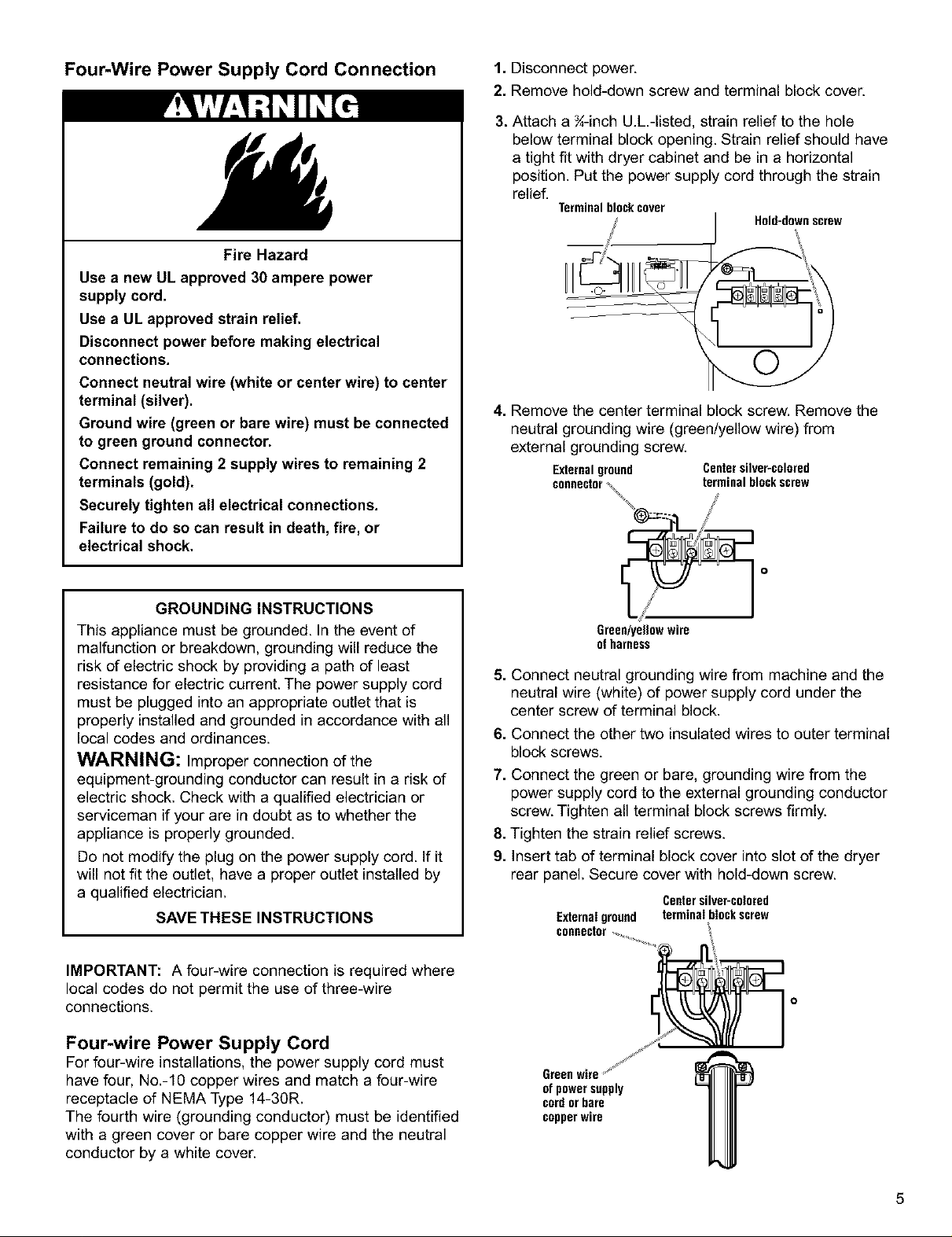
1. Disconnect power.
2. Remove hold-down screw and terminal block cover.
3. Attach a ¾-inch U.h-listed, strain relief to the hole
below terminal block opening. Strain relief should have
a tight fit with dryer cabinet and be in a horizontal
position. Put the power supply cord through the strain
relief.
Terminal block cover
Hold-downscrew
@=_n %
4. Remove the center terminal block screw. Remove the
neutral grounding wire (green/yellow wire) from
external grounding screw.
Externalground Centersilver-colored
connector_ terminal blockscrew
/
GROUNDING INSTRUCTIONS
This appliance must be grounded. In the event of
malfunction or breakdown, grounding will reduce the
risk of electric shock by providing a path of least
resistance for electric current. The power supply cord
must be plugged into an appropriate outlet that is
properly installed and grounded in accordance with all
local codes and ordinances.
WARNING: Improper connection of the
equipment-grounding conductor can result in a risk of
electric shock. Check with a qualified electrician or
serviceman if your are in doubt as to whether the
appliance is properly grounded.
Do not modify the plug on the power supply cord. If it
will not fit the outlet, have a proper outlet installed by
a qualified electrician.
SAVE THESE INSTRUCTIONS
IMPORTANT: A four-wire connection is required where
local codes do not permit the use of three-wire
connections.
Four-wire Power Supply Cord
For four-wire installations, the power supply cord must
have four, No.-10 copper wires and match a four-wire
receptacle of NEMA Type 14-30R.
The fourth wire (grounding conductor) must be identified
with a green cover or bare copper wire and the neutral
conductor by a white cover.
Green/yeg0w wire
ofharness
5. Connect neutral grounding wire from machine and the
neutral wire (white) of power supply cord under the
center screw of terminal block.
6. Connect the other two insulated wires to outer terminal
block screws.
7. Connect the green or bare, grounding wire from the
power supply cord to the external grounding conductor
screw. Tighten all terminal block screws firmly.
8. Tighten the strain relief screws.
9. Insert tab of terminal block cover into slot of the dryer
rear panel. Secure cover with hold-down screw.
Centersilver-colored
Externalground terminal blockscrew
connector
of power supply
cordor bare
copperwire
5
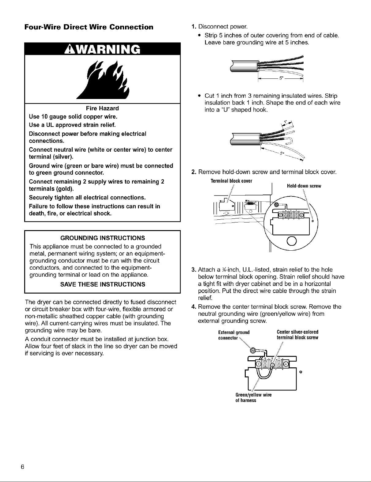
Four-Wire Direct Wire Connection 1. Disconnect power.
* Strip 5 inches of outer covering from end of cable.
Leave bare grounding wire at 5 inches.
* Cut 1 inchfrom 3 remaining insulated wires. Strip
Fire Hazard
insulation back 1 inch. Shape the end of each wire
into a "U" shaped hook.
Use 10gauge solid copper wire.
Use a UL approved strain relief.
Disconnect power before making electrical
connections.
Connect neutral wire (white or center wire) to center
terminal (silver).
Ground wire (green or bare wire) must be connected
to green ground connector.
Connect remaining 2 supply wires to remaining 2
2. Remove hold-down screw and terminal block cover.
Terminalblockcover
terminals (gold).
Securely tighten all electrical connections.
Failure to follow these instructions can result in
death, fire, or electrical shock.
Hold-downscrew
GROUNDING INSTRUCTIONS
This appliance must be connected to a grounded
metal, permanent wiring system; or an equipment-
grounding conductor must be run with the circuit
conductors, and connected to the equipment-
grounding terminal or lead on the appliance.
SAVE THESE INSTRUCTIONS
The dryer can be connected directly to fused disconnect
or circuit breaker box with four-wire, flexible armored or
non-metallic sheathed copper cable (with grounding
wire). All current-carrying wires must be insulated. The
grounding wire may be bare.
A conduit connector must be installed at junction box.
Allow four feet of slack in the line so dryer can be moved
if servicing is ever necessary.
3. Attach a ¾-inch, U.L.-listed, strain relief to the hole
below terminal block opening. Strain relief should have
a tight fit with dryer cabinet and be in a horizontal
position. Put the direct wire cable through the strain
relief.
4. Remove the center terminal block screw. Remove the
neutral grounding wire (green/yellow wire) from
external grounding screw.
Externalground Centersilver-colored
connector\ terminal blockscrew
Green/yellowwire
of harness
6
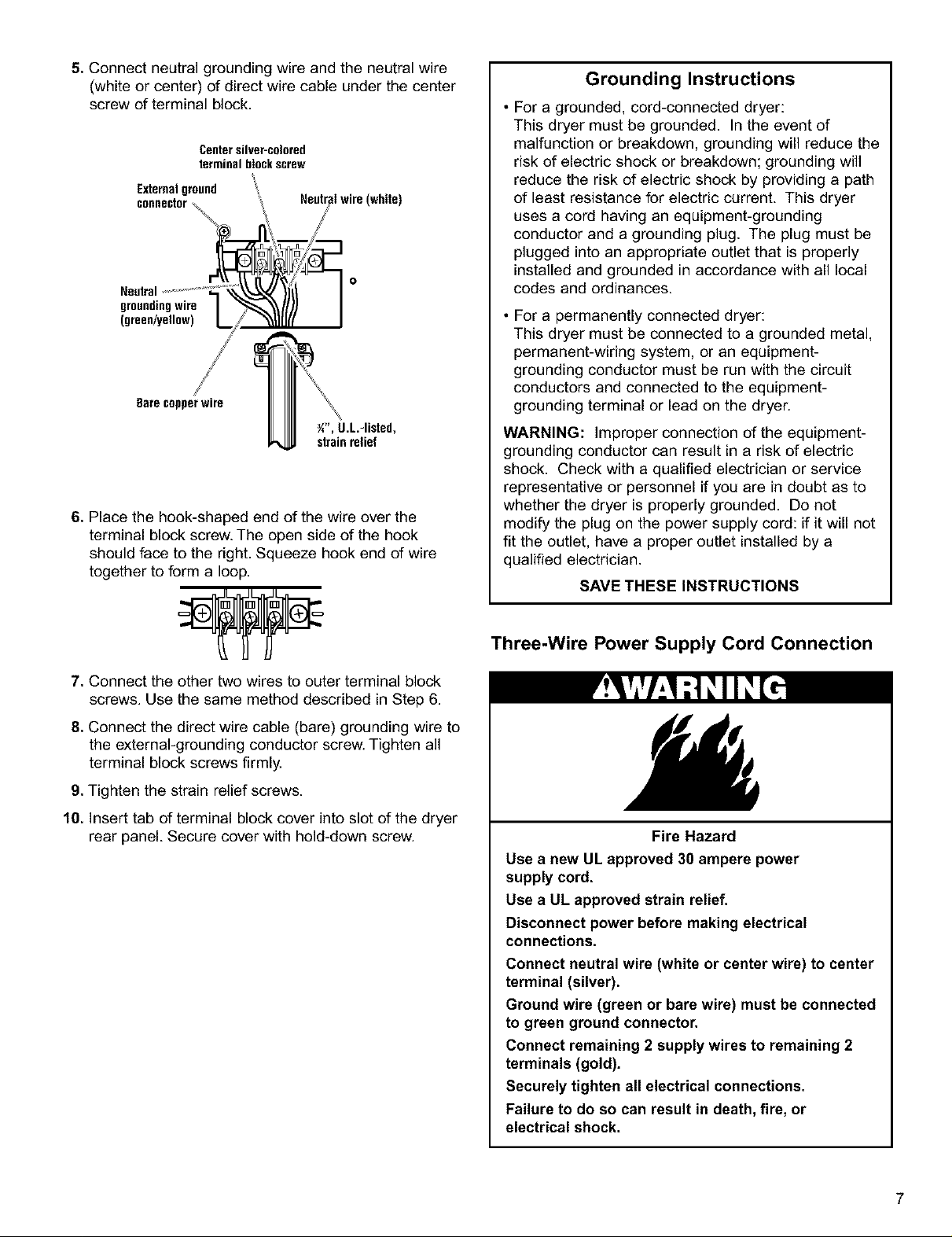
5.Connectneutralgroundingwireandtheneutralwire
(whiteorcenter)ofdirectwirecableunderthecenter
screwofterminalblock.
Centersilver-colored
terminal blockscrew
Externalground
groundingwire
(green/yellow)
Bare copperwire
Y/', U.L.-listed,
strain relief
6. Place the hook-shaped end of the wire over the
terminal block screw. The open side of the hook
should face to the right. Squeeze hook end of wire
together to form a loop.
Grounding Instructions
• For a grounded, cord-connected dryer:
This dryer must be grounded. In the event of
malfunction or breakdown, grounding will reduce the
risk of electric shock or breakdown; grounding will
reduce the risk of electric shock by providing a path
of least resistance for electric current. This dryer
uses a cord having an equipment-grounding
conductor and a grounding plug. The plug must be
plugged into an appropriate outlet that is properly
installed and grounded in accordance with all local
codes and ordinances.
• For a permanently connected dryer:
This dryer must be connected to a grounded metal,
permanent-wiring system, or an equipment-
grounding conductor must be run with the circuit
conductors and connected to the equipment-
grounding terminal or lead on the dryer.
WARNING: Improper connection of the equipment-
grounding conductor can result in a risk of electric
shock. Check with a qualified electrician or service
representative or personnel if you are in doubt as to
whether the dryer is properly grounded. Do not
modify the plug on the power supply cord: if it will not
fit the outlet, have a proper outlet installed by a
qualified electrician.
SAVE THESE INSTRUCTIONS
7. Connect the other two wires to outer terminal block
screws. Use the same method described in Step 6.
8. Connect the direct wire cable (bare) grounding wire to
the external-grounding conductor screw. Tighten all
terminal block screws firmly.
9. Tighten the strain relief screws.
10. Insert tab of terminal block cover into slot of the dryer
rear panel. Secure cover with hold-down screw.
Three-Wire Power Supply Cord Connection
Fire Hazard
Use a new UL approved 30 ampere power
supply cord.
Use a UL approved strain relief.
Disconnect power before making electrical
connections.
Connect neutral wire (white or center wire) to center
terminal (silver).
Ground wire (green or bare wire) must be connected
to green ground connector.
Connect remaining 2 supply wires to remaining 2
terminals (gold).
Securely tighten all electrical connections.
Failure to do so can result in death, fire, or
electrical shock.
7
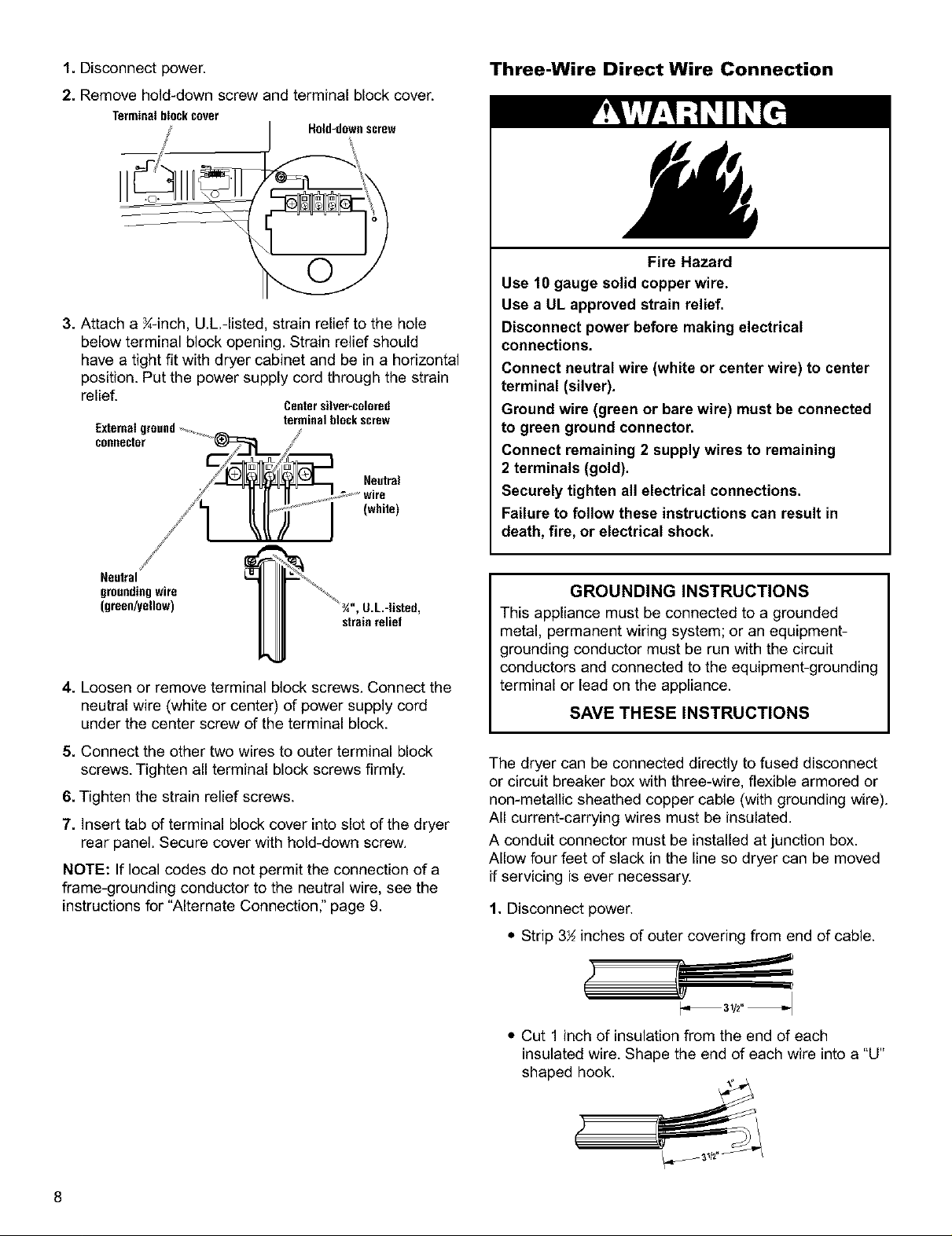
1.Disconnectpower.
2.Removehold-downscrewandterminalblockcover.
Terminal blockcover
3. Attach a K-inch, U.L.-listed, strain relief to the hole
below terminal block opening. Strain relief should
have a tight fit with dryer cabinet and be in a horizontal
position. Put the power supply cord through the strain
relief.
Externalground............,_ /
connector
/_/1 ll lt'_f'sJ "j" w'rn
Hold-downscrew
4
Centersilver-colored
terminal block screw
...... (whde),
Three-Wire Direct Wire Connection
Fire Hazard
Use 10 gauge solid copper wire.
Use a UL approved strain relief.
Disconnect power before making electrical
connections.
Connect neutral wire (white or center wire) to center
terminal (silver).
Ground wire (green or bare wire) must be connected
to green ground connector.
Connect remaining 2 supply wires to remaining
2 terminals (gold).
Securely tighten all electrical connections.
Failure to follow these instructions can result in
death, fire, or electrical shock.
/
Neutral
grounding wire
(green/yellow) ', U.L-Usted,
strain relief
4. Loosen or remove terminal block screws. Connect the
neutral wire (white or center) of power supply cord
under the center screw of the terminal block.
5. Connect the other two wires to outer terminal block
screws. Tighten all terminal block screws firmly.
6. Tighten the strain relief screws.
7. Insert tab of terminal block cover into slot of the dryer
rear panel. Secure cover with hold-down screw.
NOTE: If local codes do not permit the connection of a
frame-grounding conductor to the neutral wire, see the
instructionsfor "Alternate Connection," page 9.
GROUNDING INSTRUCTIONS
This appliance must be connected to a grounded
metal, permanent wiring system; or an equipment-
grounding conductor must be run with the circuit
conductors and connected to the equipment-grounding
terminal or lead on the appliance.
SAVE THESE INSTRUCTIONS
The dryer can be connected directly to fused disconnect
or circuit breaker box with three-wire, flexible armored or
non-metallic sheathed copper cable (with grounding wire).
All current-carrying wires must be insulated.
A conduit connector must be installed at junction box.
Allow four feet of slack in the line so dryer can be moved
if servicing is ever necessary.
1. Disconnect power.
• Strip 3½ inches of outer covering from end of cable.
• Cut 1 inch of insulation from the end of each
insulated wire. Shape the end of each wire into a "U"
shaped hook.
8
 Loading...