

Kenmore 11061812000, 11061804000, 11061802000, 11066512694 Owner’s Manual
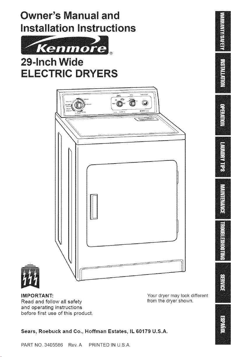
Owner's Manual and
instal lation instructions
®
29-inch Wide
ELECTRIC DRYERS
B
m rm. m rl
IMPORTANT:
Read and follow all safety
and operating instructions
before first use of this product.
Sears, Roebuck and Co., Hoffrnan Estates, IL 60179 U.S.A.
PART NO 3405586 Rev A PRINTED IN U.SA
Your dryer may took different
from the dryer shown.
BEFORE USING YOUR NEW DRYER
2
SEARS ELECTRIC DRYER WARRANTY
IMPORTANT SAFETY iNSTRUCTIONS
INSTALLATION INSTRUCTIONS
OPERATING YOUR DRYER
LAUNDRY TiPS
CARING FORYOUR DRYER
TROUBLESHOOTING
SEARS MAINTENANCE AGREEMENT
Please read this manual. It will help
you install and operate your new
Kenmore Dryer in the safest and most
economical way.
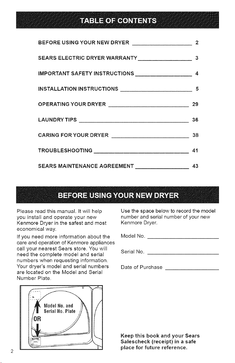
If you need more information about the
care and operation of Kenmore appliances
call your nearest Sears store. You will
need the complete model and serial
numbers when requesting information.
Your dryer's model and serial numbers
are located on the Model and Serial
Number Plate.
3
4
5
29
36
38
41
43
Use the space below to record the model
number and serial number of your new
Kenmore Dryer.
Model No.
Serial No.
Date of Purchase
Keep this book and your Sears
Salescheck (receipt} in a safe
place for future reference.
Full One Year Warranty on Warranty Restriction
Mechanical and Electrical Parts If the dryer is subjected to other than
For one year from the date of purchase, private family use, all warranty coverage
if this dryer is installed and operated
according to the instructions in this manual,
Sears will repair or replace any of its
mechanical or electrical parts if they are
defective in material or workmanship.
NOTE: Exhausting your dryer with
a plastic vent may void this warranty.
Pages 23-27 of this manual describe
the complete exhaust requirements for
this dryer.
is effective for only 90 days.
Warranty Service
Warranty service is available by contacting
your nearest Sears Service Center in the
United States.
This warranty applies only while this dryer
is in use in the United States.
This warranty gives you specific legal rights,
and you may also have other rights which
vary from state to state.
Sears, Roebuck and Co., Dept. 817WA,
Hoffrnan Estates, IL 60179.
Your safety and the safety of others is very important.
We have provided many important safety messages in this manual
and on your appliance. Always read and obey all safety messages.
This is the safety alert symbol. This symbol alerts
you to hazards that can kil! or hurt you and others.
All safety messages will be preceded by the safety
alert symbol and the word "DANGER" or "WARNING;'
These words mean:
injured if you don't follow
You will be killed or seriously
instructions.
You can be killed or seriously
injured if you don't follow
instructions.
All safety messages will identify the hazard, tell you how to reduce the
chance of injury, and tell you what can happen if the instructions are
not followed.
YOUR SAFETY iS IMPORTANT TO US.
WARNING: To reduce the risk of fire,
electric shock, or injury to persons when
using your dryer, follow basic precautions,
including the following:
• Read all instructions before using the dryer.
• Do not dry articles that have been
previously cleaned in, washed in, soaked
in, or spotted with gasoline, dry-cleaning
solvents, or other flammable or explosive
substances as they give off vapors that
could ignite or explode.
• Do not allow children to play on or in
the dryer. Close supervision of children
is necessary when the dryer is used
near children.
• Before the dryer is removed from service
or discarded, remove the door.
• Do not reach into the dryer if the drum
is moving.
• Do not install or store this dryer where it
can be exposed to water and/or weather.
SAVE THESE INSTRUCTIONS
• Do not tamper with controls.
• Do not repair or replace any part of the
dryer or attempt any servicing unless
specifically recommended in the Owner's
Manual or in published user-repair
instructions that you understand and
have the skills to carry out.
• Do not use fabric softeners or products
to eliminate static unless recommended
by the manufacturer of the fabric softener
or product.
• Do not use heat to dry articles containing
foam rubber or similarly textured rubber-
like materials.
• Clean lint screen before or after each
load.
• Keep area around the exhaust opening
and adjacent surrounding areas free from
the accumulation of lint, dust, and dirt.
• The interior of the machine and exhaust
vent should be cleaned periodically by
qualified service personnel.
IMPORTANT: Observe all governing codes and ordinances.
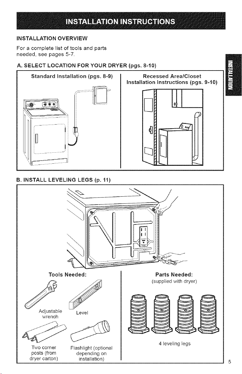
INSTALLATION OVERVIEW
For a complete list of tools and parts
needed, see pages 5-7.
A. SELECT LOCATION FOR YOUR DRYER (pgs. 8-10)
Standard Installation (pgs. 8-9)
B. INSTALL LEVELING LEGS (p. 11)
Recessed Area/C!oset
Installation Instructions (pgs. 9-10)
i
\
\
Tools Needed:
S!
Adjustable Level
wrench
Two corner Flashlight (optional
posts (from depending on
dryer carton) installation)
Parts Needed:
(supplied with dryer)
4 leveling legs
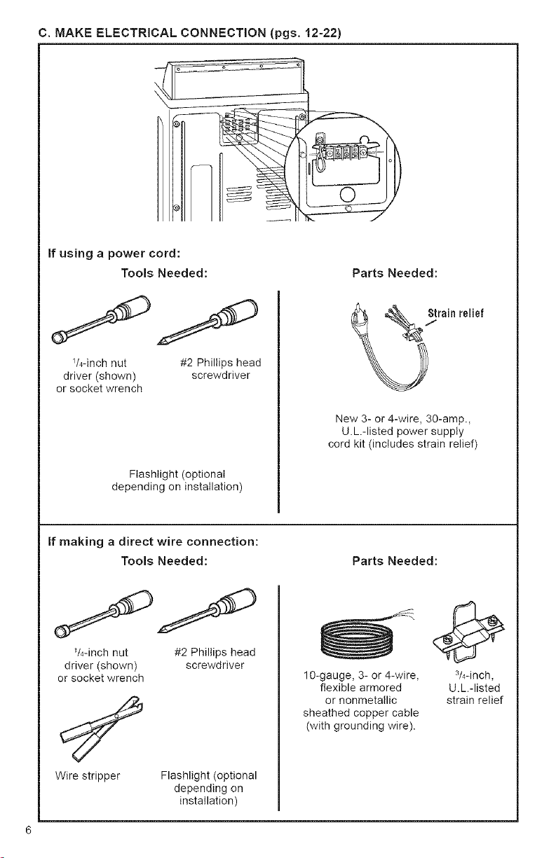
C.MAKE ELECTRICAL CONNECTION (pgs. 12-22)
@
If using a power cord:
Tools Needed:
_/4-inch nut #2 Phillips head
driver (shown) screwdriver
or socket wrench
Parts Needed:
New 3- or 4-wire, 30-amp.,
U.L.-listed power supply
cord kit (includes strain relief)
Flashlight (optional
depending on installation)
If making a direct wire connection:
Tools Needed:
_/4-inch nut #2 Phillips head
driver (shown) screwdriver
or socket wrench
Wire stripper Flashlight (optional
depending on
installation)
Parts Needed:
lO-gauge, 3- or 4-wire,
flexible armored
or nonmetallic
sheathed copper cable
(with grounding wire).
3/4-inch,
U.L.-listed
strain relief
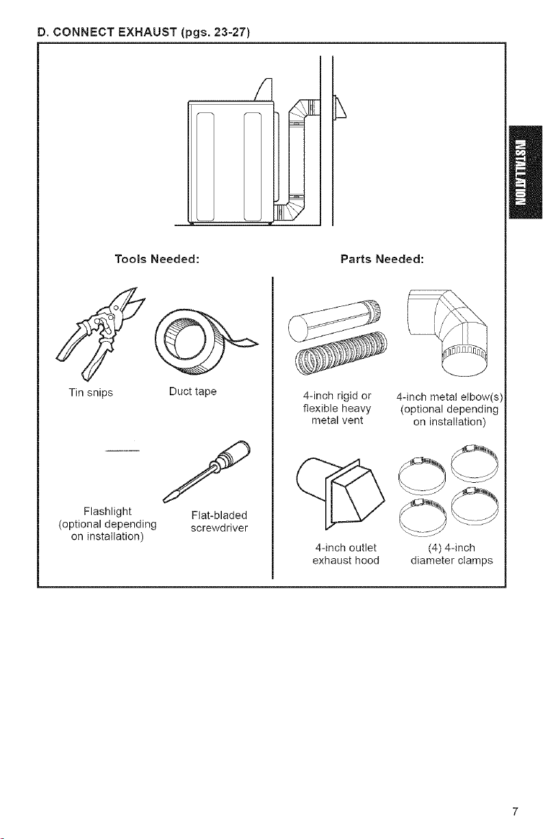
D.CONNECTEXHAUST (pgs. 23-27)
Tools Needed: Parts Needed:
Tin snips
Flashlight
(optional depending
on installation)
Duct tape
f
Fiat-bladed
screwdriver
4-inch rigid or
flexible heavy
metal vent
4-inch outlet
exhaust hood
4-inch metal elbow(s)
(optional depending
on installation)
O0
(4) 4-inch
diameter clamps
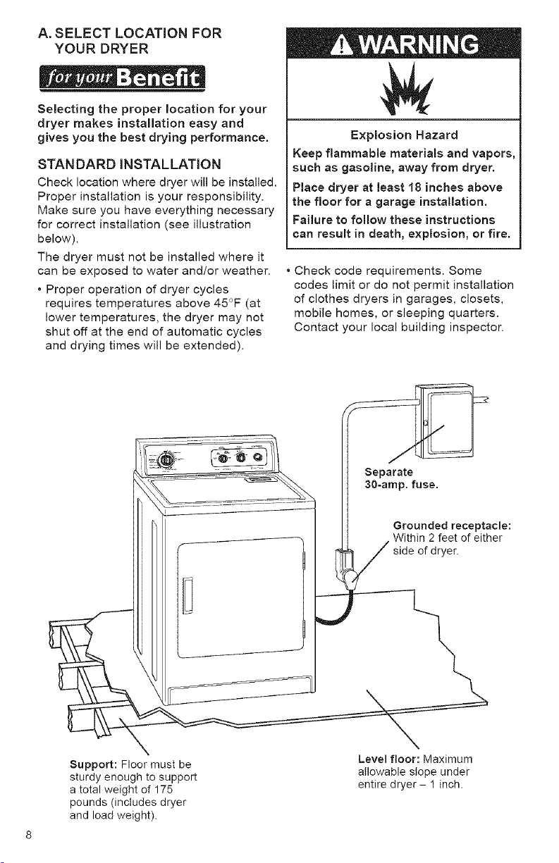
A. SELECT LOCATION FOR
YOUR DRYER
Selecting the proper location for your
dryer makes installation easy and
gives you the best drying performance.
STANDARD INSTALLATION
Check location where dryer will be installed.
Proper installation is your responsibility.
Make sure you have everything necessary
for correct installation (see illustration
below).
The dryer must not be installed where it
can be exposed to water and/or weather.
• Proper operation of dryer cycles
requires temperatures above 45°F (at
lower temperatures, the dryer may not
shut off at the end of automatic cycles
and drying times will be extended).
Explosion Hazard
Keep flammable materials and vapors,
such as gasoline, away from dryer.
Place dryer at least 18 inches above
the floor for a garage installation.
Failure to follow these instructions
can result in death, explosion, or fire.
• Check code requirements. Some
codes limit or do not permit installation
of clothes dryers in garages, closets,
mobile homes, or sleeping quarters.
Contact your local building inspector.
Support: Floor must be
X Level floor: Maximum
sturdy enough to support
a total weight of 175
pounds (includes dryer
and load weight).
30-amp. fuse.
allowable slope under
entire dryer - 1 inch.
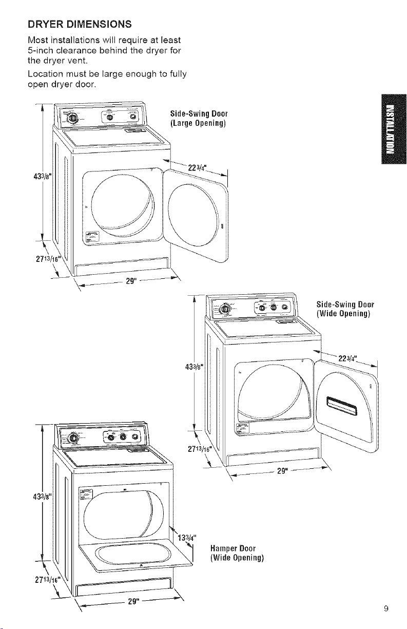
DRYERDIMENSIONS
Mostinstallationswillrequireatleast
5-inchclearancebehindthedryerfor
thedryervent.
Locationmustbelargeenoughtofully
opendryerdoor.
Side-SwingDoor
(LargeOpening)
2713
Side-SwingDoor
(WideOpening)
2713/16'
Hamper Door
(Wide Opening)
9
RECESSED AREA/CLOSET
iNSTALLATiON iNSTRUCTiONS
Check governing codes and ordinances.
This dryer may be installed in a recessed
area or closet.
The dryer must not be installed where it
can be exposed to water and/or weather.
* Proper operation of dryer cycles
requires temperatures above 45°F (at
lower temperatures, the dryer may not
shut off at the end of automatic cycles
and drying times will be extended).
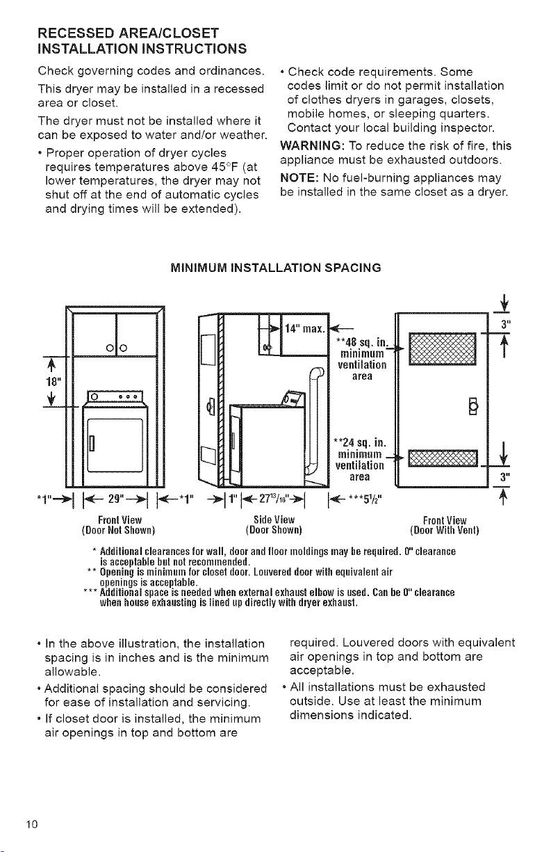
MINIMUM INSTALLATION SPACING
* Check code requirements. Some
codes limit or do not permit installation
of clothes dryers in garages, closets,
mobile homes, or sleeping quarters.
Contact your local building inspector.
WARNING: To reduce the risk of fire, this
appliance must be exhausted outdoors.
NOTE: No fuel-burning appliances may
be installed in the same closet as a dryer.
_J:
**a.8.sq. in:_
r,,lIfll I_ nil}
ventilation
area
3"
f
I I÷ 29"-H F-.1,,
FrontView SideView
(DoorNot Shown) (Door Shown)
* Additionalclearancesfor wall, doorandfloor moldingsmayhe required.0" clearance
isacceptablehnt notrecornmended.
** Openingisminirnnmforclosetdoor.Lonvereddoorwithequivalentair
openingsisacceptable.
*** Additionalspace is neededwhenexternalexhaustelbow is used.Canbe0" clearance
whenhouseexhaustingislinedupdirectly withdryerexhaust.
* In the above illustration, the installation
spacing is in inches and is the minimum
allowable.
* Additional spacing should be considered
for ease of installation and servicing.
* If closet door is installed, the minimum
air openings in top and bottom are
I0
**24 sq. in.
minimum
ventilatien
area
FrontView
(Door With Vent)
required. Louvered doors with equivalent
air openings in top and bottom are
acceptable.
* All installations must be exhausted
outside. Use at least the minimum
dimensions indicated.
3"
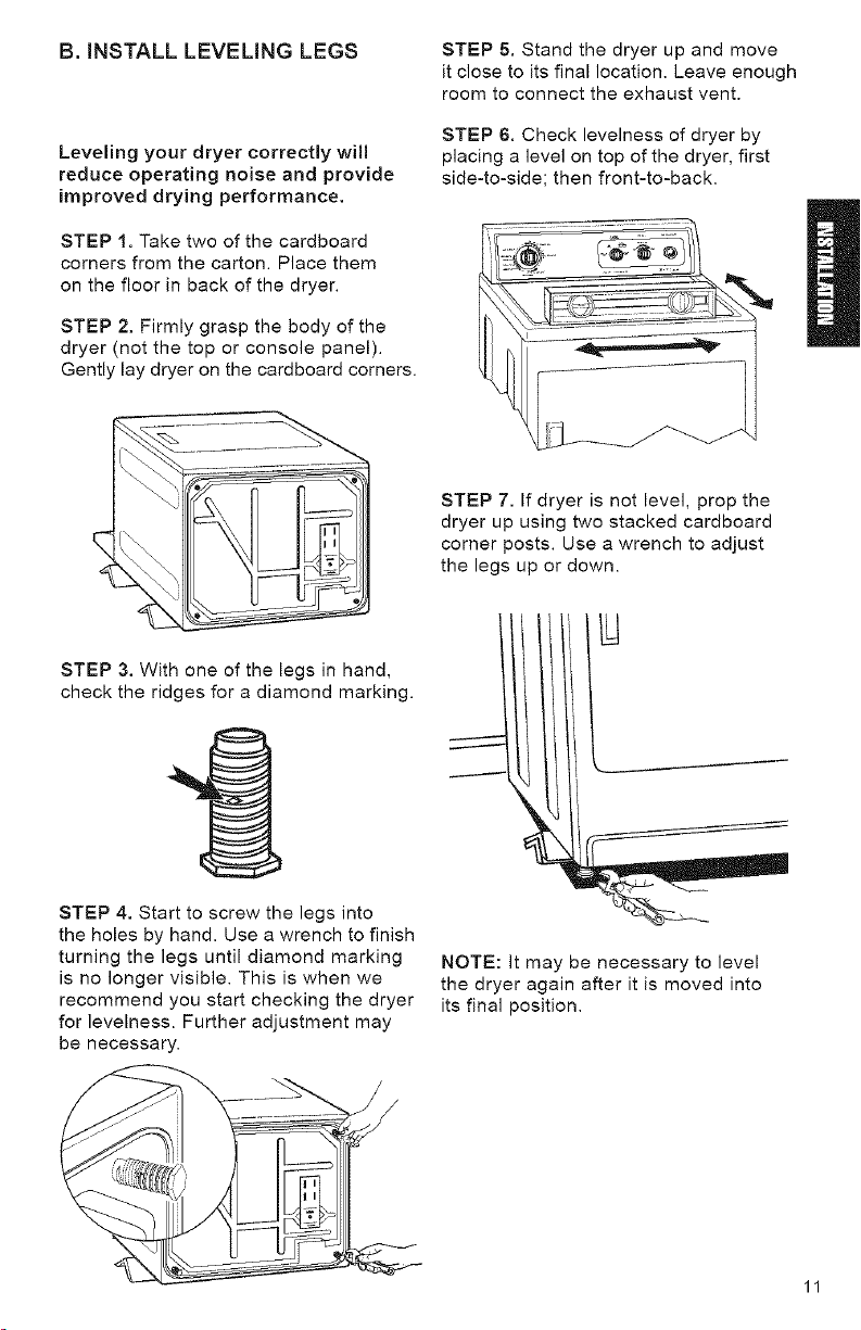
B. iNSTALL LEVELING LEGS
STEP 5. Stand the dryer up and move
it close to its final location. Leave enough
room to connect the exhaust vent.
Leveling your dryer correctly will
reduce operating noise and provide
improved drying performance.
STEP 1. Take two of the cardboard
corners from the carton. Place them
on the floor in back of the dryer.
STEP 2. Firmly grasp the body of the
dryer (not the top or console panel).
Gently lay dryer on the cardboard corners.
STEP 3. With one of the legs in hand,
check the ridges for a diamond marking.
STEP 6. Check levelness of dryer by
placing a level on top of the dryer, first
side-to-side; then front-to-back.
STEP 7. If dryer is not level, prop the
dryer up using two stacked cardboard
corner posts. Use a wrench to adjust
the legs up or down.
STEP 4. Start to screw the legs into
the holes by hand. Use a wrench to finish
turning the legs until diamond marking
is no longer visible. This is when we
recommend you start checking the dryer
for levelness. Further adjustment may
be necessary.
NOTE: It may be necessary to level
the dryer again after it is moved into
its final position.
11
C,MAKE ELECTRICAL
CONNECTION
It is your responsibility:
• To contact a qualified electrical installer.
• To assure that the electrical installation
is adequate and in conformance with
the National Electrical Code, ANSI/
NFPA 70 - latest edition and all local
codes and ordinances.
Copies of the code standards listed
above may be obtained from:
National Fire Protection Association
Batterymarch Park
Quincy, Massachusetts 02269
ELECTRICAL REQUIREMENTS
The proper electrical connection
ensures a safe installation that
meets local code requirements.
A three-wire or four-wire, single
phase, 120/240-volt, 60-Hz., AC-only,
electrical supply (or three-wire or
four-wire, 120/208-volt if specified on
serial/rating plate) is required on a
separate 30-ampere circuit, fused on
both sides of the line. A time-delay fuse
or circuit breaker is recommended.
This dryer is manufactured with the
3-wire, frame-grounding conductor
connected to the NEUTRAL (white
or center) of the wiring harness of the
terminal block. Do not have a fuse in
the neutral or grounding circuit. A fuse
in the neutral or grounding circuit could
result in an electrical shock.
Use a 4-conductor cord when the
dryer is installed in a mobile home or
an area where local codes do not
permit grounding through the neutral.
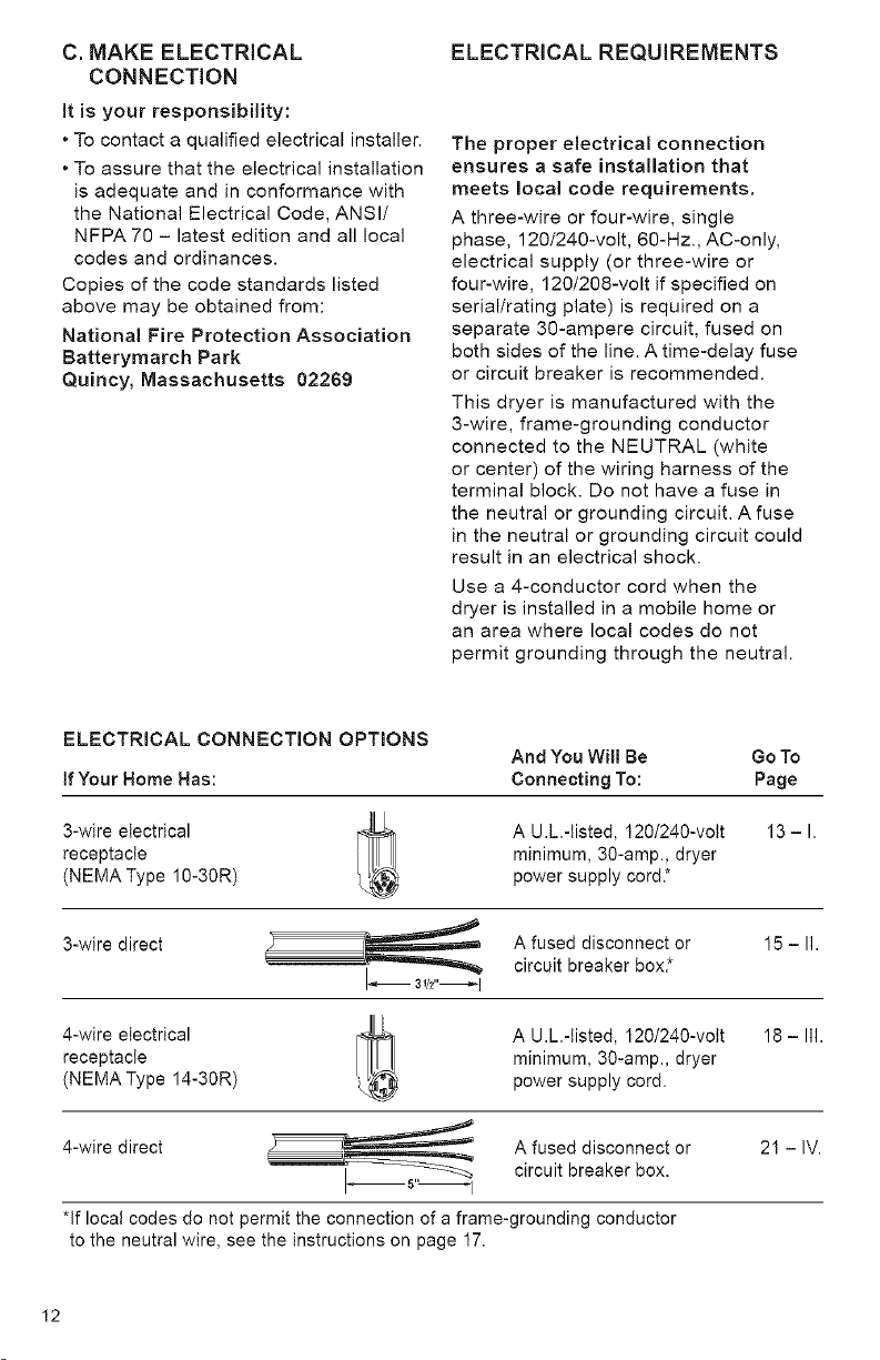
ELECTRICAL CONNECTION OPTIONS
If Your Home Has:
3-wire electrical
receptacle
(NEMA Type 10-30R)
3-wire direct A fused disconnect or 15 - II.
3,h"_l circuit breaker box*
4-wire electrical
receptacle
(NEMA Type 14-30R)
4-wire direct A fused disconnect or 21 - IV.
I_5" I circuit breaker box.
*if local codes do not permit the connection of a frame-grounding conductor
to the neutral wire, see the instructions on page 17.
I2
And You Will Be Go To
Connecting To: Page
A U.L.-tisted, 120/240-volt
minimum, 30-amp., dryer
power supply cord.*
A U.L.-listed, 120/240-volt
minimum, 30-amp., dryer
power supply cord.
18 - Ill.
13-1.
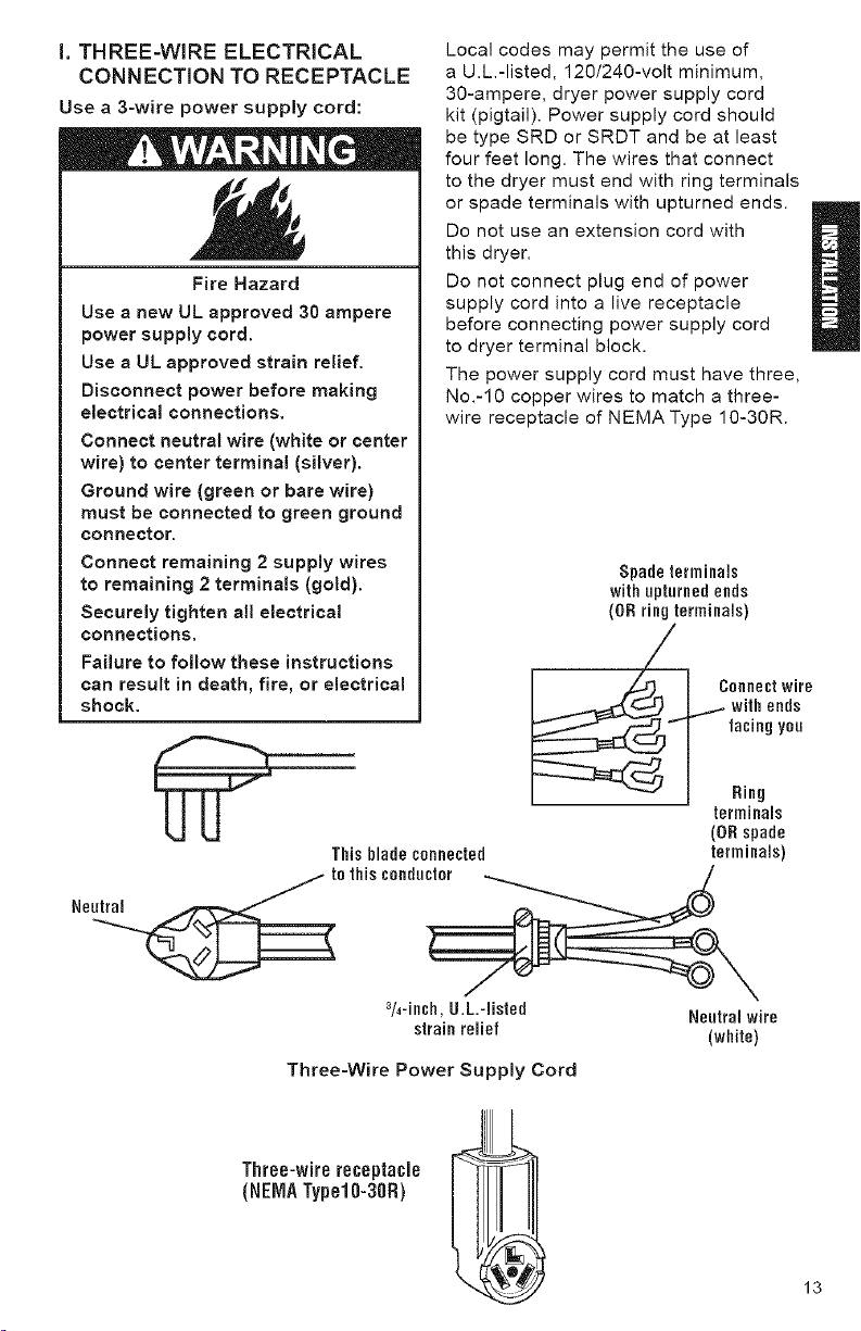
i. THREE-WIRE ELECTRICAL
CONNECTION TO RECEPTACLE
Use a 3-wire power supply cord:
Fire Hazard
Use a new UL approved 30 ampere
power supply cord.
Use a UL approved strain relief.
Disconnect power before making
electrical connections.
Connect neutral wire (white or center
wire) to center terminal (silver).
Ground wire (green or bare wire)
must be connected to green ground
connector.
Connect remaining 2 supply wires
to remaining 2 terminals (gold).
Securely tighten all electrical
connections.
Failure to follow these instructions
can result in death, fire, or electrical
shock,
Local codes may permit the use of
a U.L.-listed, 120/240-volt minimum,
30-ampere, dryer power supply cord
kit (pigtail). Power supply cord should
be type SRD or SRDT and be at least
four feet long. The wires that connect
to the dryer must end with ring terminals
or spade terminals with upturned ends.
Do not use an extension cord with
this dryer.
Do not connect plug end of power
supply cord into a live receptacle
before connecting power supply cord
to dryer terminal block.
The power supply cord must have three,
No.-10 copper wires to match a three-
wire receptacle of NEMAType 10-30R.
Spade terminals
with upturned ends
(OR ring terminals)
This blade connected
_te this conductor
%-inch,U.L.-listed
strainrelief
Three=Wire Power Supply Cord
Three-wirereceptacle
(NEIVlATypel0-30R)
terminals
(0R spade
terminals)
Neutral wire
(white)
13
GROUNDINGINSTRUCTIONS
Thisappliancemustbegrounded.
Intheevent of malfunction or break-
down, grounding will reduce the risk
of electric shock by providing a path
of least resistance for electric current.
The power supply cord must be plugged
into an appropriate outlet that is properly
installed and grounded in accordance
with all local codes and ordinances.
WARNING: improper connection of the
equipment-grounding conductor can
result in a risk of electric shock. Check
with a qualified electrician or serviceman
if your are in doubt as to whether the
appliance is properly grounded.
Do not modify the plug on the power
supply cord. If it will not fit the outlet,
have a proper outlet installed by a
qualified electrician.
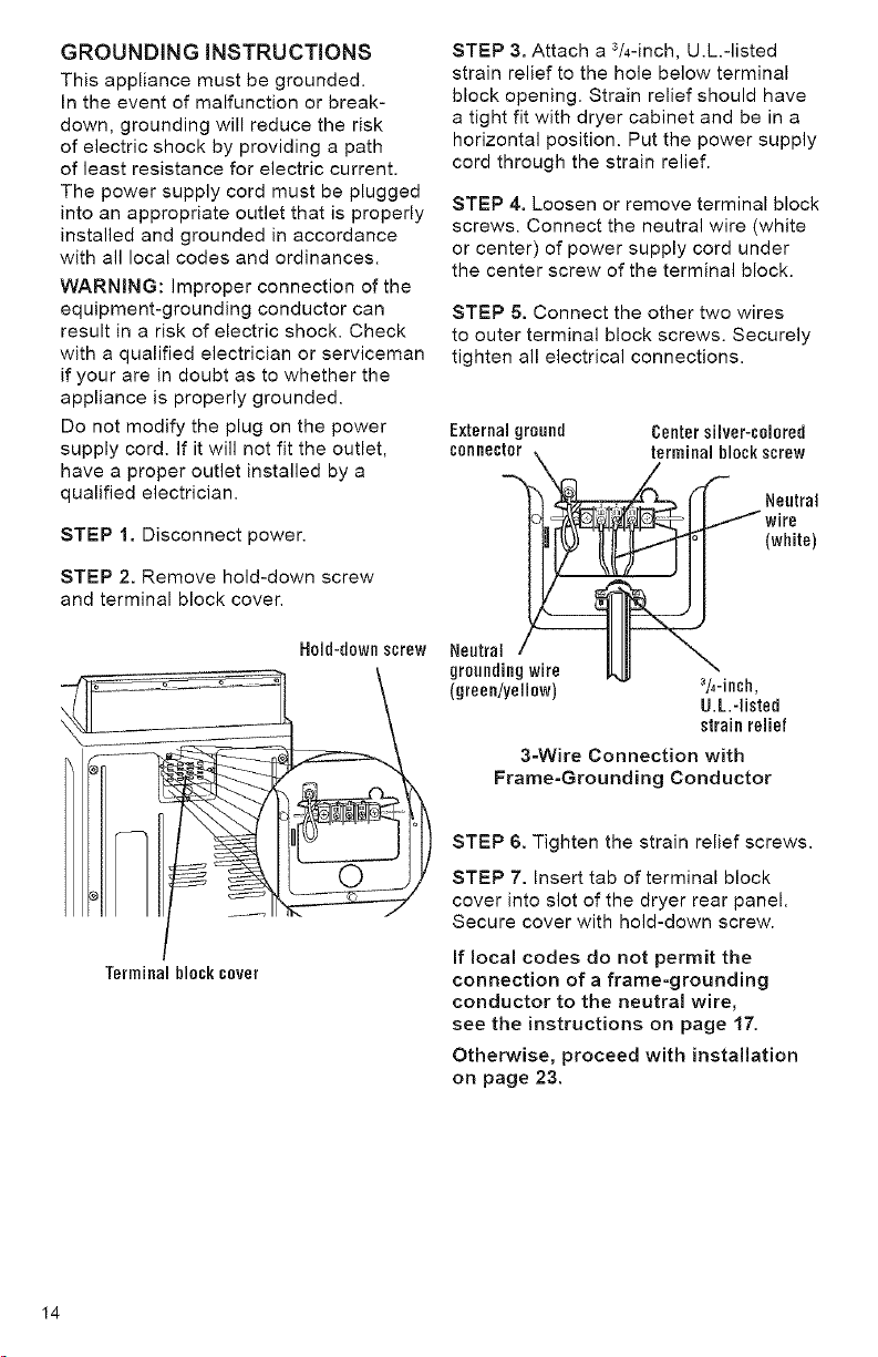
STEP 1. Disconnect power.
STEP 2. Remove hold-down screw
and terminal block cover.
STEP 3. Attach a 3/4-inch, U.L.-listed
strain relief to the hole below terminal
block opening. Strain relief should have
a tight fit with dryer cabinet and be in a
horizontal position. Put the power supply
cord through the strain relief.
STEP 4. Loosen or remove terminal block
screws. Connect the neutral wire (white
or center) of power supply cord under
the center screw of the terminal block.
STEP 5. Connect the other two wires
to outer terminal block screws. Securely
tighten all electrical connections.
External ground Center silver-colored
connector _ 2rminal blockscrew
(white)
Terminalblosksever
H01d-d0wnscrew
Neutral / III \
grounding wire _ "-
(green/yellow) 3/4-inch,
U.L.-listed
strain relief
3=Wire Connection with
Frame-Grounding Conductor
STEP 6. Tighten the strain relief screws.
STEP 7. Insert tab of terminal block
cover into slot of the dryer rear panel.
Secure cover with hold-down screw.
If local codes do not permit the
connection of a frame=grounding
conductor to the neutral wire,
see the instructions on page 17.
Otherwise, proceed with installation
on page 23.
I4
 Loading...