

Kenmore 11027022710, 11027022711 Installation Guide

Installation Instructions
Instrucciones de instalación
English / Español
Table of Contents / Índice......2
Kenmore®
Commercial Washer
Lavadora comercial
P/N W10837709A
Sears Brands Management Corporation
Hoffman Estates, IL 60179 U.S.A.
www.kenmore.com

Table of Contents
Índice
WASHER SAFETY .................................................................................. 3
TOOLS & PARTS .................................................................................... 4
DIMENSIONS ......................................................................................... 5
LOCATION REQUIREMENTS ............................................................... 6
DRAIN SYSTEM ...................................................................................... 7
ELECTRICAL REQUIREMENTS ............................................................. 8
INSTALLATION INSTRUCTIONS ......................................................... 9
CONNECT DRAIN HOSE ....................................................................10
CONNECT INLET HOSES .....................................................................11
LEVEL WASHER ....................................................................................12
INSTALLING COIN SLIDE AND COIN BOX ....................................12
COMPLETE INSTALLATION ................................................................13
TYPICAL FULL LOAD SIZES .................................................................13
WASHER MAINTENANCE ..................................................................14
ALTERNATE PARTS & ACCESSORIES ................................................14
WARRANTY ........................................................................................... 15
ASSISTANCE OR SERVICE ............................................. BACK COVER
SEGURIDAD DE LA LAVADORA ......................................................... 16
HERRAMIENTAS Y PIEZAS .................................................................. 17
DIMENSIONES ..................................................................................... 18
REQUISITOS DE UBICACIÓN ............................................................ 19
SISTEMA DE DESAGÜE ...................................................................... 20
REQUISITOS ELÉCTRICOS ................................................................... 21
INSTRUCCIONES DE INSTALACIÓN ................................................ 22
CONEXIÓN DE LA MANGUERA DE DESAGÜE ..............................23
CONEXIÓN DE LAS MANGUERAS DE ENTRADA ......................... 24
NIVELACIÓN DE LA LAVADORA ....................................................... 25
INSTALACIÓN DEL TRAGAMONEDAS
Y LA CAJA DE MONEDAS ................................................................. 25
COMPLETE LA INSTALACIÓN ......................................................... 26
TAMAÑOS DE CARGAS TÍPICAS DE VOLUMEN COMPLETO ..... 26
MANTENIMIENTO DE LA LAVADORA ............................................ 27
PIEZAS Y ACCESORIOS ALTERNATIVOS ........................................ 27
GARANTÍA ............................................................................................ 28
AYUDA O SERVICIO TÉCNICO ............................CONTRAPORTADA
2
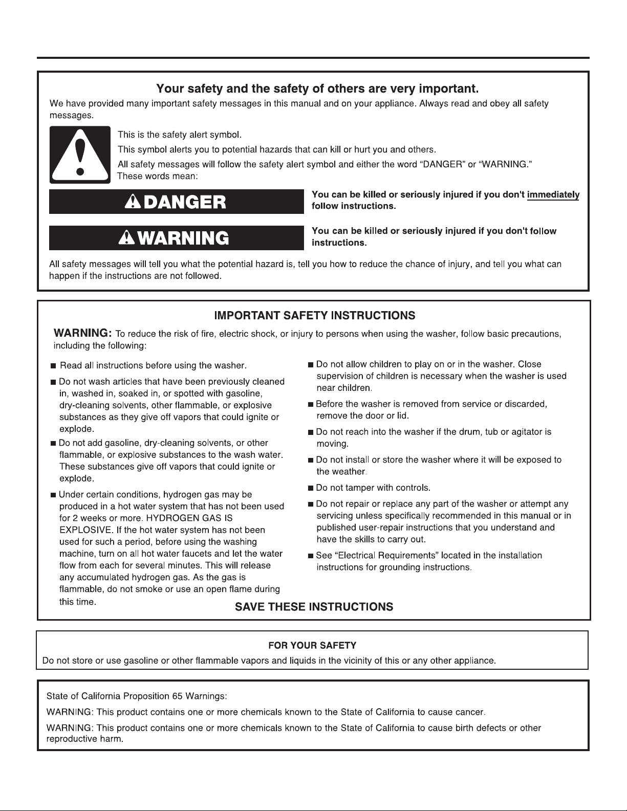
WASHER SAFETY
3
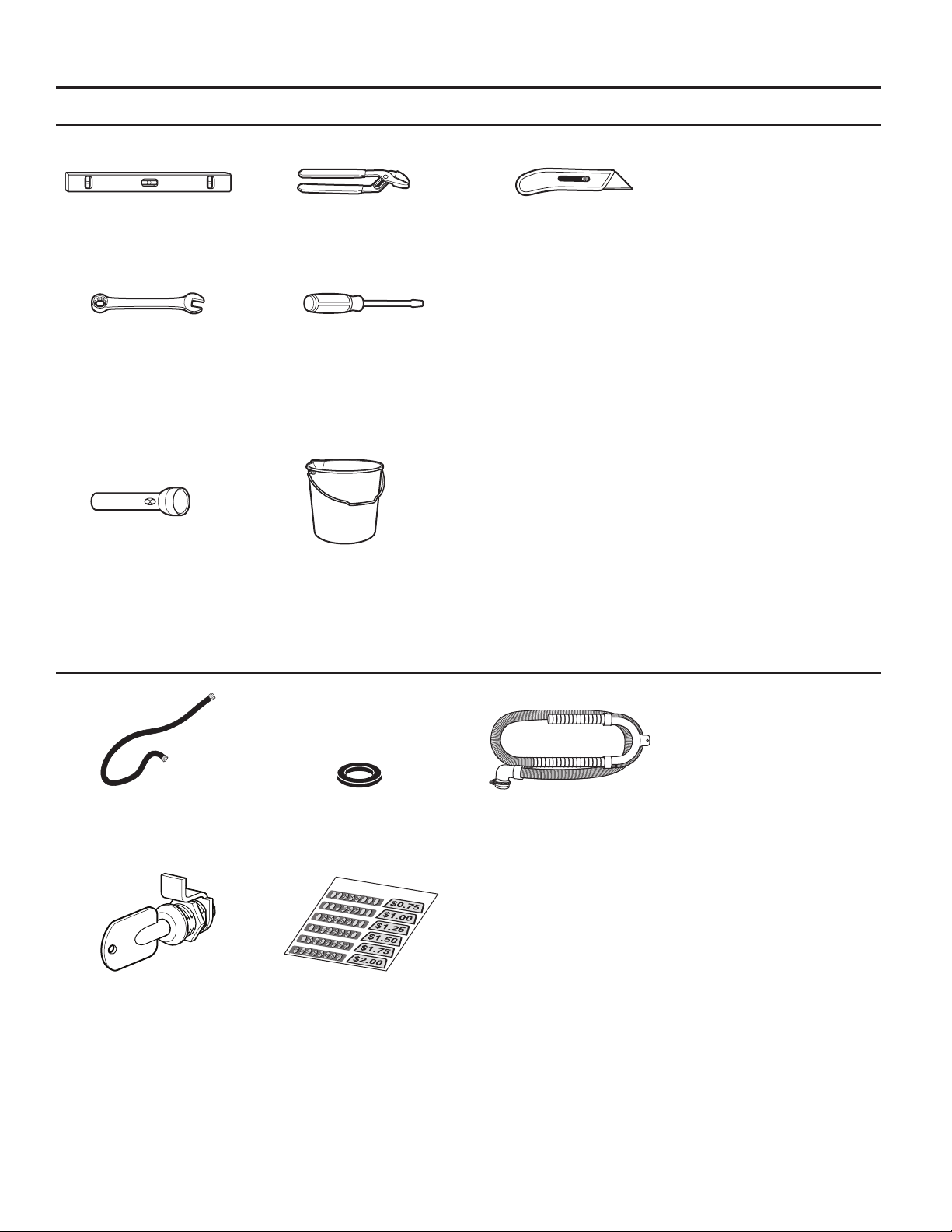
TOOLS & PARTS
Tools Needed:
Level Pliers Utility Knife
9/16" (14 mm)
Open-End Wrench
Optional tools:
Flashlight Bucket
Parts Supplied:
Flat-Blade Screwdriver
Water Inlet Hoses (2) Inlet Hose Washers (4)
Service Door Lock
Assembly
4
Coin Slide Decal Kit
Drain hose with clamp,
U-form, and cable tie
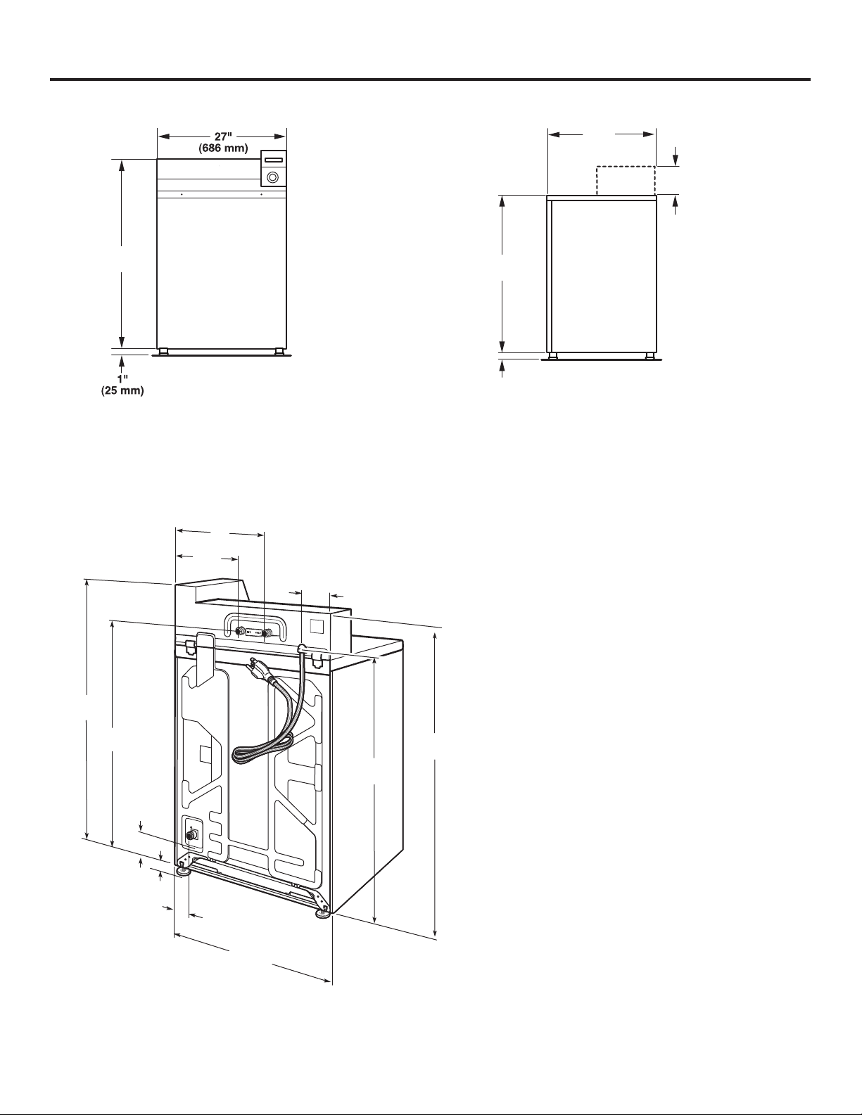
DIMENSIONS
27"
Front View Side View
(686 mm)
1
8
/4"
(210 mm)
421/2"
(1.080 m)
361/4"
(921 mm)
1"
(25 mm)
Back View
16"
(406 mm)
101/2"
(267 mm)
51/2"
(140 mm)
441/2"
(1.130 m)
371/4"
(946 mm)
421/2"
(1.080 m)
363/4"
(933 mm)
63/4"
(171 mm)
1"
(25 mm)
41/4"
(108 mm)
27"
(686 mm)
5
LOCATION REQUIREMENTS
Selecting the proper location for your washer improves
performance and minimizes noise and possible washer “walk.”
Your washer can be installed in a basement, laundry room,
or recessed area. See “Drain System.”
Companion appliance location requirements should also be
considered.
IMPORTANT: Do not install or store the washer where it will
be exposed to the weather. Do not store or operate the washer
in temperatures at or below 32°F (0°C). Some water can remain
in the washer and can cause damage in low temperatures.
Proper installation is your responsibility.
You will need:
■ A water heater set to 120°F (49°C).
■ A grounded electrical outlet located within 4 ft. (1.2 m) of
power cord on back of washer. See “Electrical Requirements.”
■ Hot and cold water faucets located within 4 ft. (1.2 m)
of hot and cold water ll valves on washer, and water pressure
of 20–100 psi (138–690 kPa). A pressure reduction valve should
be used in the supply line where inlet pressure entering the
building exceeds 100 PSI (690 kPa) to avoid damage to the
washer mixing valve.
■ Single washer installations require 12" (300 mm) minimum
risers to provide an air cushion and avoid noise and damage
to valves.
■ A level oor with maximum slope of 1" (25 mm) under entire
washer. Installing on carpet is not recommended.
■ Floor must support washer’s total weight (with water and load)
of 315 lbs (143 kgs).
■ A oor drain under the bulkhead. Prefabricated bulkheads
with electrical outlets, water inlet lines, and drain facilities
should be used only where local codes permit.
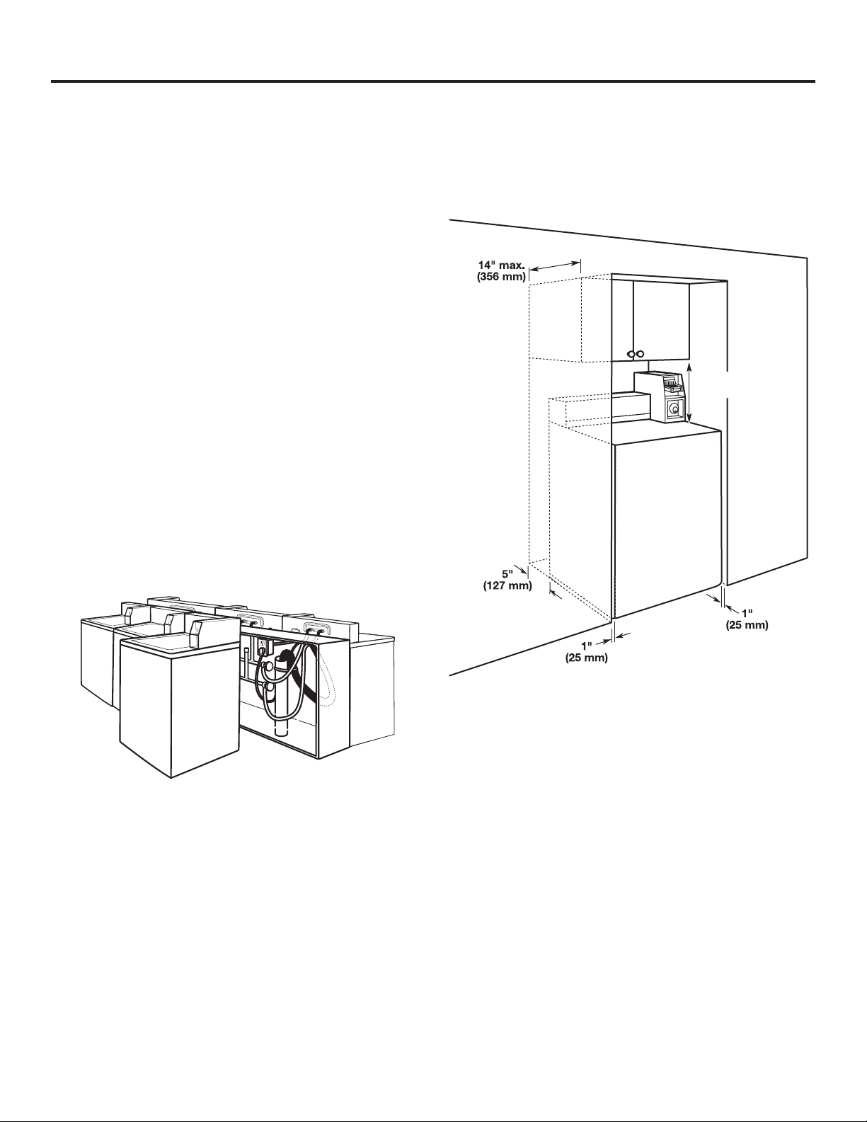
Recessed Area or Closet Installation
This washer may be installed in a recessed area. The installation
dimensions shown are the minimum spaces allowable. Additional
spacing should be considered for ease of installation and
servicing. Companion appliance spacing should be considered.
Minimum installation spacing
16"
(406 mm)
6
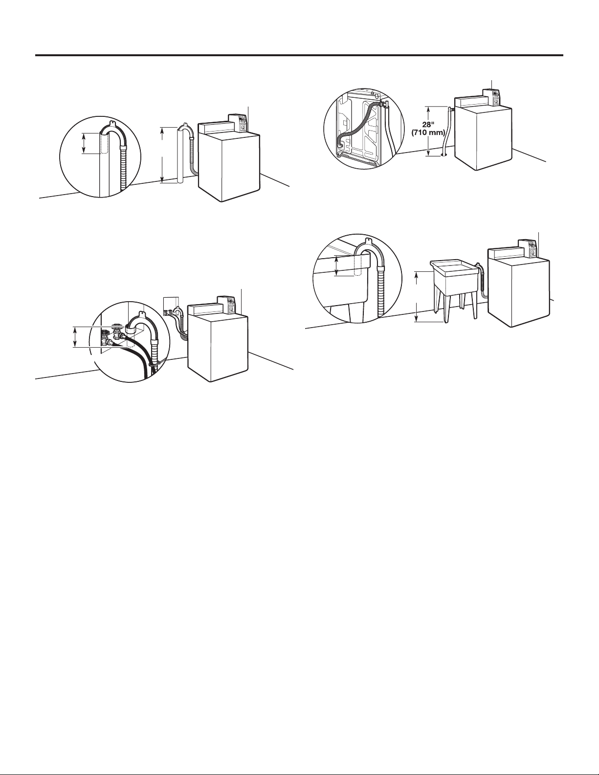
DRAIN SYSTEM
8"
(203 mm)
Drain system can be installed using a oor drain, wall standpipe,
oor standpipe, or laundry tub. Select method you need.
Floor standpipe drain system
39"
8"
(203 mm)
Minimum diameter for a standpipe drain: 2" (51 mm). Minimum
carry-away capacity: 10 gal. (38 L) per minute. Top of standpipe
must be at least 39" (990 mm) high; install no higher than
96" (2.44 m) from bottom of washer.
(990 mm)
Wall standpipe drain system
8"
(203 mm)
Floor drain system
Floor drain system requires a Siphon Break Kit (Part Number
285320). Minimum siphon break: 28" (710 mm) from bottom
of washer. Additional hoses may be needed.
Laundry tub drain system
39"
(990 mm)
Minimum capacity: 20 gal. (76 L). The top of the laundry tub
must be at least 39" (990 mm) above oor.
See requirements for oor standpipe drain system.
7
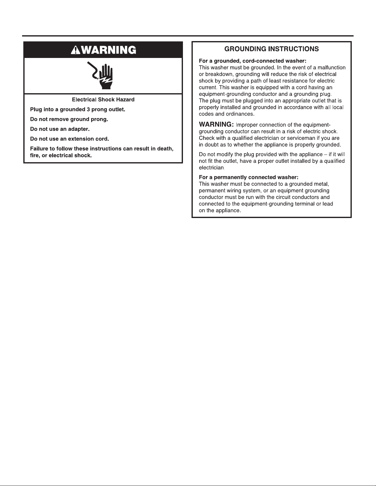
ELECTRICAL REQUIREMENTS
■ A 120-volt, 60-Hz., AC-only, 15- or 20-amp, fused electrical
supply is required. A time-delay fuse or circuit breaker is
recommended. It is recommended that a separate circuit
breaker serving only this appliance be provided.
■ This washer is equipped with a power supply cord having
a 3 prong grounding plug.
■ To minimize possible shock hazard, the cord must be plugged
into a mating, 3 prong, grounding-type outlet, grounded in
accordance with local codes and ordinances. If a mating outlet
is not available, it is the personal responsibility and obligation
of the customer to have the properly grounded outlet installed
by a qualied electrician.
■ If codes permit and a separate ground wire is used, it is
recommended that a qualied electrician determine that
the ground path is adequate.
■ Do not ground to a gas pipe.
■ Check with a qualied electrician if you are not sure the
washer is properly grounded.
■ Do not have a fuse in the neutral or ground circuit.
8
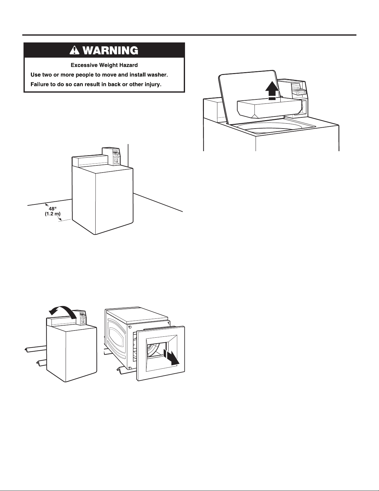
INSTALLATION INSTRUCTIONS
It is necessary to remove all shipping materials for proper
operation and to avoid excessive noise from washer.
1. Move washer to within 4 ft (1.2 m) of its nal location; it must
be in a fully upright position.
NOTE: To avoid oor damage, set washer onto cardboard
before moving it and make sure lid is taped shut.
3. Remove tape from washer lid, open lid, and remove cardboard
packing tray from tub. Be sure to remove all parts from tray.
NOTE: Keep tray in case you need to move washer later.
2. To avoid damaging oor, place cardboard supports from
shipping carton on oor behind washer. Tip washer back
and place on cardboard supports. Remove shipping base.
Set washer upright.
IMPORTANT: Removing shipping base is necessary for proper
operation.
NOTE: Keep shipping base in case you need to move washer
later.
9
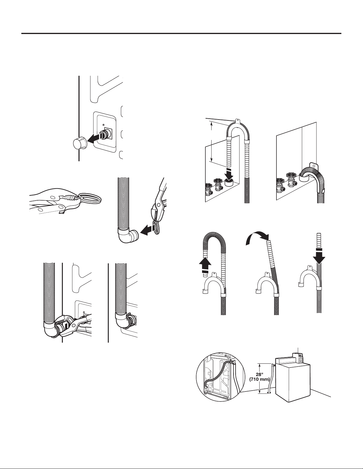
CONNECT DRAIN HOSE
Proper routing of the drain hose avoids damage to your oor
due to water leakage.
Remove drain hose from the washer drum
1. Remove cap from the washer drain port on the back of
the washer.
2. If clamp is not already in place on elbow end of drain hose,
slide it over end as shown.
5. Place hose into standpipe (shown in picture) or over side
of laundry tub.
IMPORTANT:
■ Drain hose is not to exceed 8" (203 mm) into drain pipe;
do not force excess hose into standpipe or lay on bottom
of laundry tub. Drain hose form must be used.
■ It is the responsibility of the installer to install and secure
the drain hose into the provided plumbing/drain in a
manner that will avoid the drain hose coming out of,
or leaking from, the plumbing/drain.
Drain
hose
form
8"
(203 mm)
6. For oor drain installations, you will need to remove the drain
hose form from the end of the drain hose. You may need
additional parts with separate directions. See “Tools and Parts.”
3. Squeeze clamp with pliers and slide elbow end of drain
hose onto washer drain port and secure with clamp.
4. The washer drain system can be installed using a oor drain,
wall standpipe, oor standpipe, or laundry tub.
7. The oor drain system requires a siphon break that may be
purchased separately. The siphon break (Part Number 285320)
must be a minimum of 28" (710 mm) from the bottom of the
washer. Additional hoses might be needed.
10
 Loading...