

Page 1
®
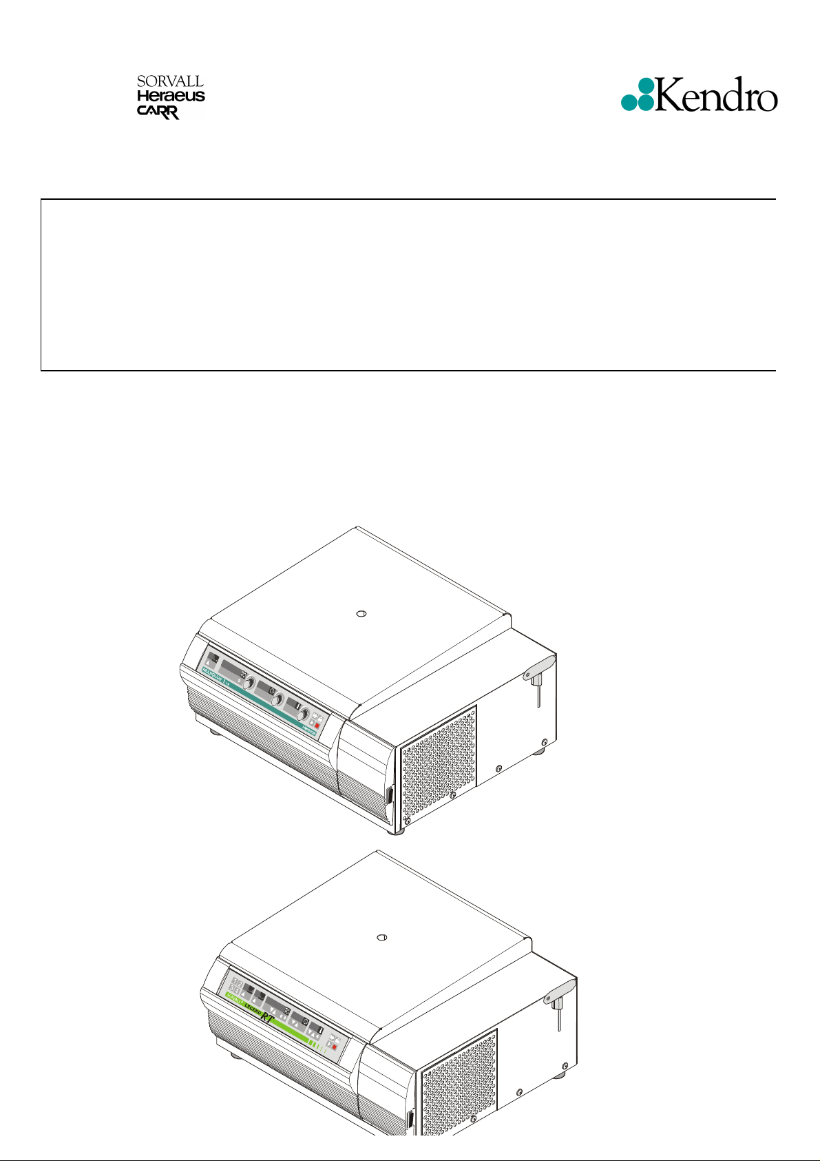
Multifuge
3 S-R/3 L-R, Legend® RT
120V 50/60 Hz
SERVICE MANUAL P/N 12004376
Page 2
TABLE OF CONTENTS
Section Title Doc.- No. Page
1 OPERATING INSTRUCTIONS
2 SERVICE
2.1 Servicing Schedule 2-1/2
2.2 Trouble Shooting 2-3
2.3 Error Code 2-4/7
2.4 Test Points 2-8
2.5 Imbalance Behavior 2-9
2.6 Cleaning of Instrument Parts 2-9
2.7 Electrical Safety Check 2-10
3 FUNCTIONAL DESCRIPTION
3.1 Block Functions 3-1
3.2 Main Board Functions 3-1/2
3.3 Key and Indication Board - Easycontrol 3-3
Key and Indication Board - Quickcontrol 3-4
3.4 Speed Detection Board 3-5
3.5 Rotor Indication 3-5
3.6 Imbalance Detection 3-5
3.7 Lid Lock System 3-5
3.8 Cooling Plant 3-5
4 DIAGRAMS
4.1 Block Diagram 4-1
4.2 Wiring Diagrams 4-2/3
4.3 Wiring Connection Diagrams 4-4/6
4.4 Main Board, Component Plan 4-7/14
4.5
4.6 Speed detection, Component Plan 4-17
4.7 Sensor Board, Component Plan 4-18
4.8 Rotor Detection Board, Component Plan 4-19/20
4.9 Cooling Plant 4-21
5 DISASSEMBLY OF INSTRUMENT PARTS
5.1 Housing / Casing Parts 5-1/2
5.2 Electrical Components 5-2/3
5.3 Drive Components 5-3/4
5.4 Cooling Plant 5-4
6 SPARE PART FIGURES AND LISTS
6.1 Spare Part Figures 6-1/9
6.2 Spare Part Lists
7 TECHNICAL BULLETINS
Display Board, “Easycontrol” Keypad version,
Component Plan
Display Board, “Quickcontrol” Rotary switch
version, Component Plan
4-15
4-16
8 Preventive maintenance checklist
Calibration Certificate
Edition: 03 TABLE OF CONTENTS
22.11.01 AH Page: 0 - 2
Legend RT
Multifuge 3S-R / 3L-R
Page 3

Service
Service
2.1 Servicing Schedule (yearly procedure recommended)
2.1.1 Maintenance Routine without Dismantling the Centrifuge
2.1.1.1 Electrical Installation and Safety
• Switch OFF the centrifuge and disconnect the unit from power, check voltage supply and mains
fusing (16 Amps, slow blow characteristic)
• Check condition of plug and wall socket - replace defective parts (customer’s responsibility)
• Check cord condition and fixing / connection - replace or refit it
• Check condition of instrument socket and replace it in case of bad contacts
2.1.1.2 Location and Mechanical Inst allati on
• Check the base (ground, table, lorry with lockable wheels etc.) for resonance-free and stable
conditions
• Check for a well ventilated place and sufficient distances to walls or adjacent equipment, without
exposition to direct sunlight
• Check the leveling of the centrifuge drive with use of a spirit level
2.1.1.3 Lid Tumbler Mechanism and Safety Device
• Connect the centrifuge to power and switch ON
• Check for correct automatic lid closing and self-acting lid opening - if in disorder, readjust lid,
swivel hinges, and/or locking devices
• Check the rubber gasket for lid’s and bolt’s sealing and replace, if damaged
• For checking the electronically safety circuit: start the centrifuge, let it shortly run and stop it, the
lid must not be unlocked by the microprocessor as long as the speed is more than 60 rpm - if
safety circuit is out of function, replace main board
2.1.1.4 Cleanliness of Spin Chamber and Motor Casing
• Open the lid and remove the rotor (for loosening turn the T-handle Allen key (5mm) in arrow
direction - see rim of rotor chamber)
• Clean the spin chamber with a dry and absorbent cloth (remove all dust and moisture - see also
section for Cleaning)
• Check the cleanliness of the motor flange and take care of the annular slot around the motor shaft:
penetrating fluids can damage the upper spindle bearing or electronics, remove fluids with an
injector and/or absorbent paper
2.1.1.5 Rotor and Accessories Condition and Sealing, bellows
• Check the condition of rotors and accessory parts (especially all supporting or stressed partitions):
the rotor and/or accessory parts must not be used any longer, if there are visible traces of
mechanical damage or rust
• Check the condition of rotor and/or accessory sealing and replace them in case of malfunction
• Bellows of gas lid stays have to be greased upside down with glycerin (part no. 70902649) once a
year.
2.1.1.6 Rotor Fixing and Drive Spindle
• Check the perfect condition of the collet chuck and replace it in case of malfunction (thread is worn
out, horizontal grooves etc. )
• Check the condition of the drive cone: the centrifuge must not be used any longer, if the drive
cone is damaged (e.g. bend or it’s bearings are worn out)
Edition: 04 Servicing Schedule
18.04.02/he/AH Page: 2 - 1
Legend RT
Multifuge 3S-R/3L-R
Page 4

Service
2.1.1.7 Temperature Level (not at every unit)
• Check the wire gauze (behind the air inlet slots) left and right side for free ventilation, insufficient
air flow will lead to an inadmissible temperature rise of compressor, motor and electronic parts
2.1.1.8 Imbalance Behavior
• Install available and empty rotors and check the imbalance behaviour with rotor dependant cut off
and run through weights (see 2.5) and replace worn out motor rubber mounts, faulty main board or
sensor board
2.1.2 Maintenance Routine after Dismantling the Centrifuge Casing
2.1.2.1 Motor Supporting Elements
• Check the supporting and damping elements of the drive motor and replace them in case of
increased rubber abrasion or abundance of imbalance but at least every 3 years
2.1.2.2 Braking Circuit
• Check the function of the braking circuit (warming up of brake resistor, even and noiseless brake
effect) and replace defective parts in case of malfunction
2.1.2.3 Lead and Screwing Connections
• Check the terminal and plug connections of all leads and on all boards and electrical components,
tighten all loosen screwing connections, refit or replace defective parts
• Check the wedged connections of the board, mechanical and electrical components and re-tighten
them if necessary (use screw locking lacquer for motor mounts and lid lock assembly)
2.1.2.4 Protection Earth Core and Groundi ng Con necti ons
• Check the protection earth core for continuity and all grounding plug connectors (see also 2.7
Electrical Safety Check)
• Check isolation resistance and accessible current (see 2.7)
Edition: 04 Servicing Schedule
18.04.02/he/AH Page: 2 - 2
Legend RT
Multifuge 3S-R/3L-R
Page 5
r
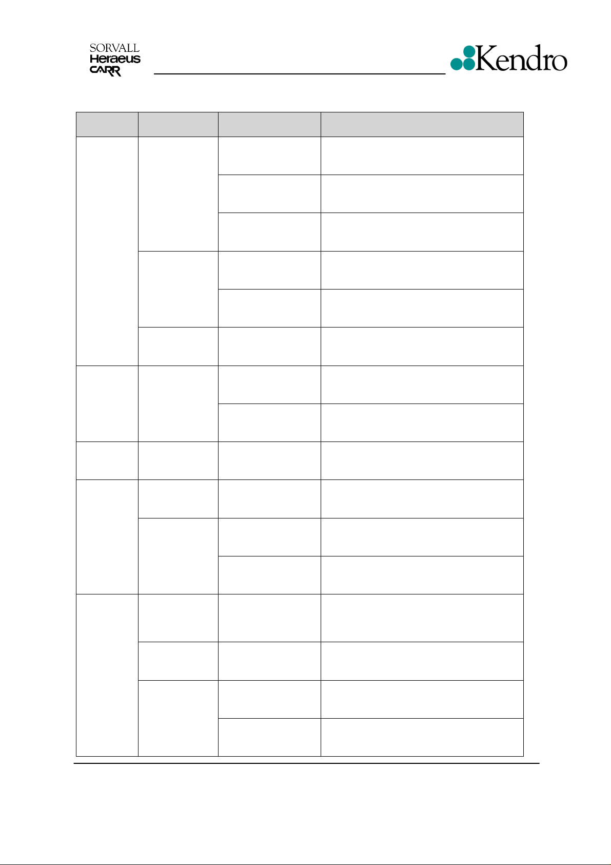
2.2 Trouble Shooting
Error
Indication
Error Cause
Service
Possible Error
Source
Mains switch with
integrated fuse or
fuses on main board
Corrective Procedure
Switch on again, disconnect electric.
components success., search for other
faults
Displays
remain
dark
All display
Elements
are shortly
illuminated
Constant
No mains
voltage supply
No low voltage
supply for
indication board
Interrupted
program
CPU program
reset may be
caused by EMI
Interruption Parameter NV-RAM No or defective NV-RAM
Mains fuse or circuit
breaker failed
Faulty mains cord or
instrument socket
Faulty connection
from CPU to
indication board
Faulty indication or
CPU board
NV-RAM out of
socket or not
correctly placed
Reduced voltage
supply (<10%)
Bad or missing
ground connection
Check fuse or circuit breaker and replace o
switch on again
Check instrument cord and socket, replace
defective parts
heck connections on CPU, indication board
and connecting leads, replace defective
parts
Replace main board completely
Insert the valid NV-RAM and push it
correctly into socket
Remedy the failure if the voltage drops
often, use a voltage stabilizer
Check all ground connections and the
ground connection of all boards
Drive
makes
noises -no
good
separation
result
Lid cannot
be opened
by key at
standstill
Edition: 04 Servicing Schedule
18.04.02/he/AH Page: 2 - 3
Mechanics
Electrical
Locking drive is
not supplied
with voltage
Latch motor Faulty motor winding Replace complete motor
Lid is not
correctly locked
wear out of motor
rubber mount
Defective terminal
connection, faulty
lead or motor winding
Faulty power electr. Replace main board
24V supply
faulty relay K2
faulty driving circuit
Lid bolt is jamming
Lid is deformed Re-adjust the lid centrally
Replace motor rubber mounts (at least
winding resistances -see test points on
Push lid centrally into lock and press the
every three years)
Check voltage on motor terminal and
main board
Check voltage for drive motor
Check switch. after power ON
Replace the main board
No or defective NV-RAM
key again
Legend RT
Multifuge 3S-R/3L-R
Page 6
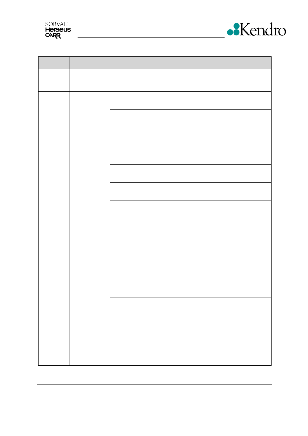
2.3 Error code
Error
Indication
„rotor“ in
speed
display
Error Cause
Wrong selection
of detected rotor
Service
Possible Error
Source
Inadmissible speed
or rcf value was pre-
selected
Corrective Procedure
Press start again (within 15s), else wait for
rotor standstill, lid OPEN/CLOSE, set value,
start
“bAL“
message
appears in
speed
display
“Lid“
appears in
speed
display
Imbalance run
Lid was opened
manually during
run
Protection circuit
(20V) interrupted
during run
Rotor not symmetri-
cally loaded
Base is not sturdy
enough and comes
into vibrations
Centrifuge drive is
not correctly leveled
Rotor itself has
imbalance
Drive shaft or rotor
fixing is damaged
Imbalance sensor Replace sensor board
Circuits of main
board
Forbidden
intervention
emergency opening
device must only be
used at standstill
Defective micro
switch or leads or
connectors to micro
switch are interrupted
Open lid, check rotor loading, close lid again
and restart
Change or reinforce the base (table, lorry with
lockable wheels, etc.)
Level the drive correctly by means of unit’s
feet
Rotor must no longer be used, send back to
Kendro
Replace collet chuck or motor
Replace the main board
Close lid immediately, turn power OFF/ON,
press lid down for locking, press start key,
press stop to finish run
Check leads and connectors to micro switch,
in case of a faulty micro switch, replace them
Loose plug
„OPEn“
appears in
speed
display by
supposedly
closed lid
“S-LID”
appears in
display
Edition: 04 Servicing Schedule
18.04.02/he/AH Page: 2 - 4
20V supply for
protection circuit
is interrupted at
standstill
Sensor signal not
clear
connectors
Interrupted leads to
micro switch
Defective micro
switch
Latch not in valid
position during power
on
Check plug X20
Check leads to micro switch for continuity
Replace micro switch
Switch unit “off” and “on” again
Legend RT
Multifuge 3S-R/3L-R
Page 7
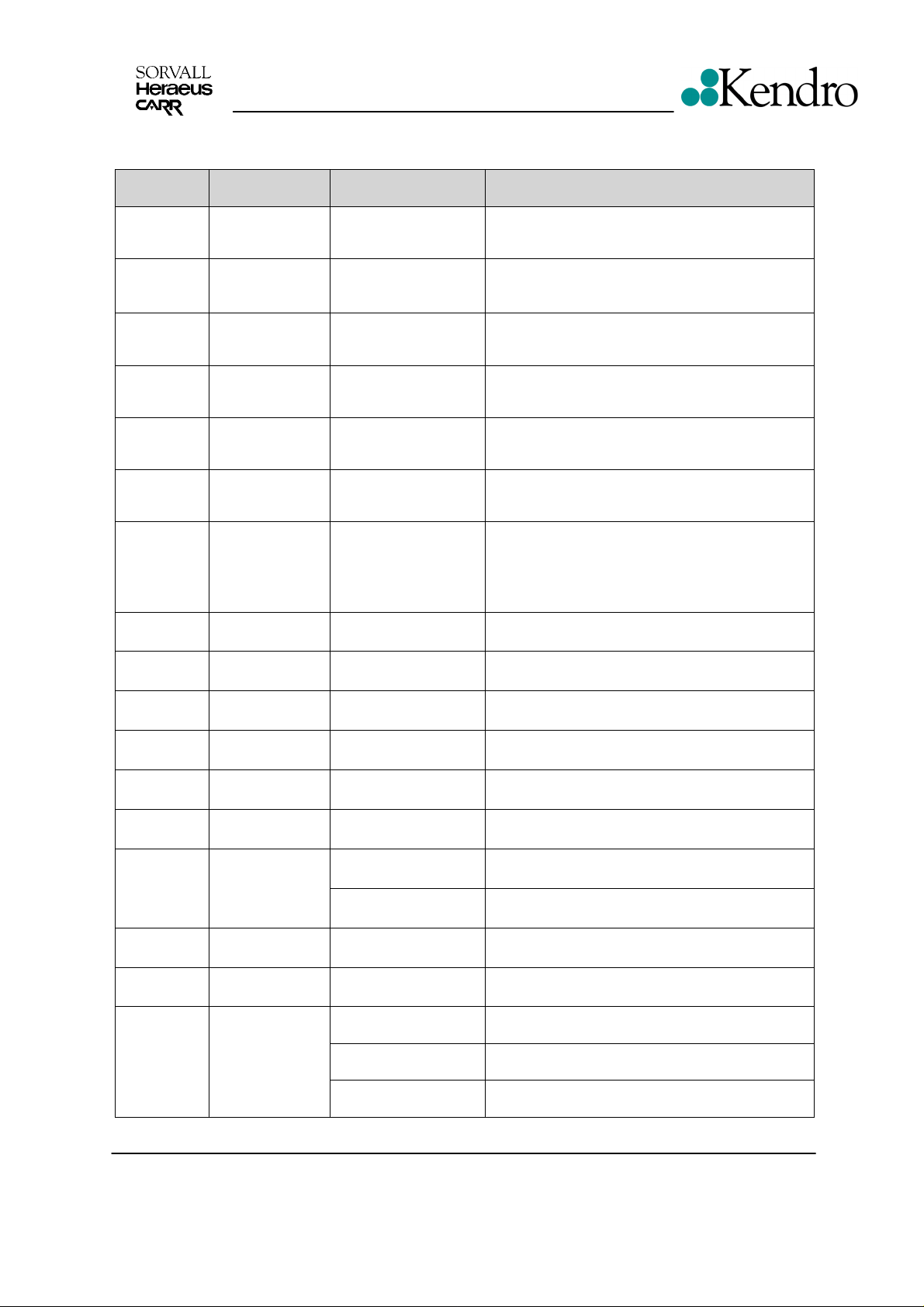
Error
Indication
Error Cause
Service
Error Code
Possible Error
Source
Corrective Procedure
„E-01“
message
„E-02“
message
„E-03“
message
„E-04“
message
“E-05”
message
“E-06”
message
“E-07”
message
“E-08”
message
“E-09”
message
“E-10”
message
“E-11”
message
“E-12”
message
“E-13”
message
„E-14“
message
System clock
pulse not stable
program
sequence was
disturbed
Stack overflow
Stack underflow
Reset by HW
watchdog timer
Data lines to key
board disturbed
Display board
doesn’t match to
main board
cooled/non-
cooled
Check sum error
E-PROM
Check sum error
NV RAM
NV RAM not
initialized
NV RAM doesn’t
match E-PROM
Check sum error
NV RAM
Check sum error
NV RAM
chamber over
temperature:
display >50°C
Hardware fault on
main board
Internal Software
problem
Internal Software
problem
Internal Software
problem
Software problem No action in the field possible
Wiring display board Check wiring and connectors
Check software Replace NV RAM and CPU
E-PROM failed Replace E-PROM
NV RAM failed Replace NV RAM
Initializing of NV-RAM
is not valid
Check versions of NV
RAM and E-PROM
NV RAM failed Replace NV RAM
NV RAM failed Replace NV RAM
Compressor didn’t
work
Faulty cooling cycle Exp. valve, refrigerant loss
Change CPU, replace main board
check NV-RAM and socket, insert the correct
Check leads, terminals, start relay, capacitor,
Change main board
No action in the field possible
No action in the field possible
NV-RAM
Replace NV RAM and E-PROM
compressor
„E-15“
message
„E-16“
message
„E-17“
message
Edition: 04 Servicing Schedule
18.04.02/he/AH Page: 2 - 5
Open temp.
sensor
Short cut temp.
sensor
wrong or faulty
rotor detection
Check sensor, control
circuits
Check sensor, control
circuits
a wrong rotor was
installed
Mains voltage failure press stop key, wait for standstill and restart
Faulty detection
circuit
wait for standstill, open the lid and install a
Replace sensor or main board
Replace sensor or main board
correct rotor
replace the main board
Legend RT
Multifuge 3S-R/3L-R
Page 8
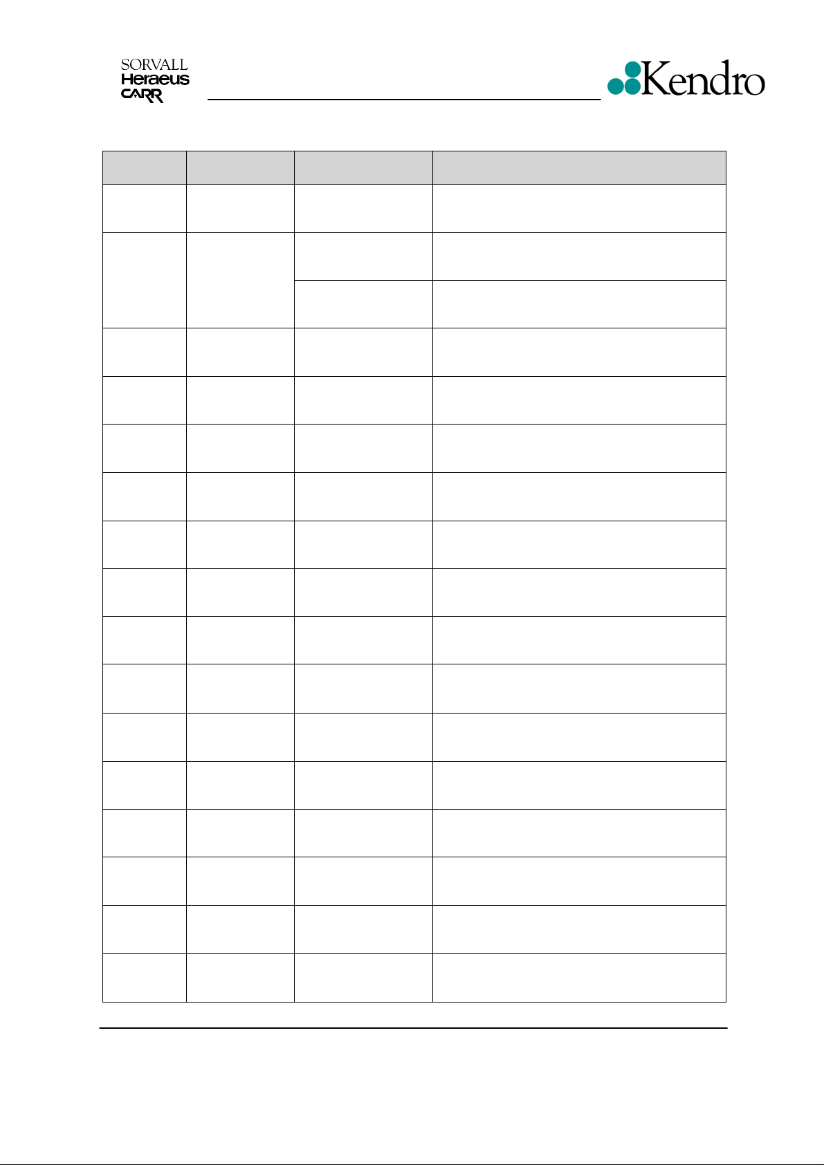
Error
Indication
„E-18“
message
„E-19“
message
Error Cause
Bucket code
not valid for this
rotor
Rotor code not
programmed
Service
Error Code
Possible Error
Source
Corrective Procedure
Not valid
Wrong rotor installed Check rotor
Interference during
recognition
Check rotor recognition board and wiring
„E-20“
message
„E-21“
message
„E-22“
message
„E-23“
message
„E-24“
message
„E-25“
message
„E-26“
message
„E-27“
message
„E-28“
message
rotor code not
valid
Recognition
disturbance
Speed signal
disturbance
Speed control
measuring
disturbance
Latch not in top
position
Time out latch
open
Time out latch
close
Signal given by
latch not valid
Wrong sense of
rotation
See E-19
wiring Check wiring
wiring Check wiring
nd
2
check was done
by rotor recognition
Check speed detection board
system
Micro switch failed,
Check micro switch adjustment, if necessary
de-adjusted, latch
Hall sensor signal not
applied
Hall sensor signal not
applied
Check latch motor and PCB
Check latch motor and PCB
Wrong identified
signal after power
“on”
After replacement of
the motor- wires
mixed
replace it
Check hall sensors
Check wiring at terminal
„E-29“
message
„E-30“
message
„E-31“
message
„E-32“
message
„E-33“
message
Motor doesn’t
turn
Control-voltage
interruption
over-
temperature
motor >150°C
Over-
temperature
Electronic
High-pressure
Cooling system
PCB faulty, see E-21,
E-22
PCB failed Replace PCB
Hot motor, no air
circulation
Faulty main board Replace main board
Faulty high pressure
switch, blocked
system
Edition: 04 Servicing Schedule
18.04.02/he/AH Page: 2 - 6
Change PCB, rotor recognition, speed
detection, fasten motor wiring at terminal
Check motor, check grill for dust
Inspect cooling system
Legend RT
Multifuge 3S-R/3L-R
Page 9

Error
Indication
Error Cause
Service
Error Code
Possible Error
Source
Corrective Procedure
„E-34“
message
„E-35“
message
„E-36“
message
„E-37“
message
„E-38“
message
„E-39“
message
„E-40“
message
„E-41“
message
Over-voltage
Over-current Main board Replace main board
NMI
interruption
Over-current
continuously
Current
measurement
disturbed
Speed control
check >n max.
Acceleration of
the unit is too
slow
Offset voltage
from the
imbalance
sensor is in a
inadmissible
area
Brake resistor,
main board
Over voltage or over-
current
Main board Replace main board
Analog signal >
hardware over current
Speed > calculated
speed
Big imbalance
Motor or main board
faulty
Imbalance sensor
faulty
Wiring from the speed
detection board to the
main board is broken
Check brake resistors, replace main board
Replace main board
Replace main board
Check speed detection board, replace the
main board
Check rotor loading, motor and main board
Replace speed detection board
Check / replace the wiring
Edition: 04 Servicing Schedule
18.04.02/he/AH Page: 2 - 7
Legend RT
Multifuge 3S-R/3L-R
Page 10
Service
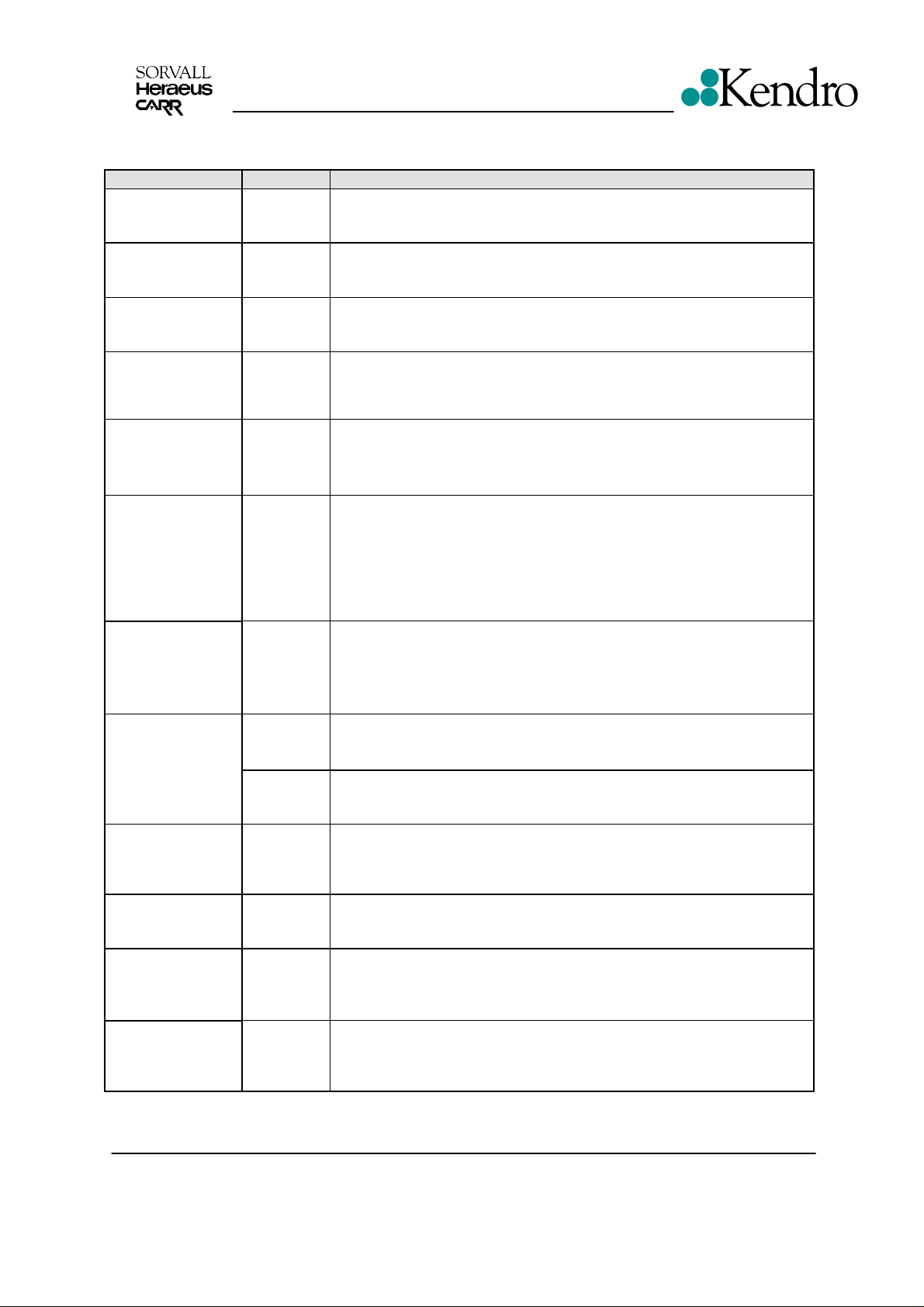
2.4 Test Points
Test Points Unit Value Conditions
Mains terminal
Board resistance
Motor over-temp.
terminal
X20/B3,B4*
Over-press switch
terminal X20/P
Fans cooling plant
terminal XK
Compressor
terminal XG
terminal box
–insulation value
Speed detection
plug XW
(1 to 4)
(3 to 4)
speed
Imbalance sensor
plug XW
(1→4)
(2→4)
120V
50Ω
20V DC
20V DC
100 Ω
82 Ω
6,5 A
1,6 Ω
4,8 Ω
> 10MΩ
5V DC
4,4V
0V
n=f*30
12V DC
a(t)
All given values are related on 120 V (+/- 10%) mains voltage for
board supply
Voltage drop by one disconnected lead (error case) and linked
terminal XR
Voltage drop by one disconnected lead (error case) and linked
terminal XO
Switch OFF unit, fan resistance temperature 20°C
wire black to blue
wire brown to blue
Switch OFF unit, compressor temp. 20°C
Resistance of main coil + (starting relay 0.1Ω)
Resistance of auxiliary coil (joints 13 -> 14)
Resistance inter phase and motor casing
Board with active filter circuit
Low voltage supply
Light barrier is passed through (slot position)
Light barrier is out (turn cone a little by hand)
When centrifuge is running
Low voltage supply of sensor board
Amplitude of lateral acceleration is rotor and speed dependent,
analyzed for n > 250 rpm
Motor current I
M
cable (U,V,W)
Motor winding
resistance 20°C –
insulation value
Brake resistor
terminal XD
Rotor detection
plug XR
Temp. measuring
plug XU
3 * 7A
3 * 5,2A
3 * 3,0A
3x2,5Ω
> 10MΩ
60Ω
5V DC
0V DC
Switch OFF unit, 2 resistors parallel connected, resistance at
pulse pause lengths, this pulse mode is generated by 4 alternately
Split core transformer with Flukemeter
maximum during acceleration
Rotor #6441, set speed = 3750min
Switch OFF unit, pull off motor plugs, measure inter
U -> V, V -> W, W -> U
Resistance inter each phase and motor casing
Per rotor revolution 2 different long
pulses are separated from 2 different
Chamber temperature 20°C (PT100:
Chamber temperature -10°C (PT100:
Chamber temperature 40°C (PT100:
Edition: 04 Servicing Schedule
18.04.02/he/AH Page: 2 - 8
20°C
polarized magnets
-1
, 560W
≈
108Ω)
96Ω)
≈
≈
116Ω)
Legend RT
Multifuge 3S-R/3L-R
Page 11

Service
2.5 Imbalance Behaviour
• Install in table available rotor(s) in unloaded condition
Rotor/Bucket Run through
weight
75006445/75006441 20 grams 30 – 40 grams
• Insert rotor dependent cut-off weights and position them at angles of 90° to each other, the
centrifuge must stop 4 tim es indicating “bAL“ message - in case of false behaviour see trouble
shooting: no “bAL“ indicatio n.
• Insert the admissible imbalance weights in the same manner, the centrifuge must run through 4
times to maximum rotor speed.
2.6 Cleaning of Instrument Parts
ATTENTION - WARNING!
The electrical and electronic components must not be cleaned with moist detergents!
For Cleaning the centrifuge housing or its accessories see Operating Instructions section 1
(maintenance and care).
• Electronic components
Clean dusty components carefully with a dry and soft brush and remove loose dust with a
vacuum cleaner.
• Fans
Scratch off car efully with a knife or similar tool the cr usted dirt from the fans ’ blades. Resulting
grooves or marks must be removed subsequently with a fine abrasive cloth. Loose dirt is to
remove with an absorbent cloth or vacuum cleaner.
• Vent holes
Remove dirt from the vent grid behind the front panel by using a brush and vacuum cleaner.
• Condensers of cooling plant (if available)
The louvers between the c ondensers’ heat air deflect ors have to be vacuum c leaned. In case of
persistent dirt the unit must be carried to an appropriate place where the condensers can be
cleaned with compressed air from inside to outside. Bended heat air deflectors have to be
realigned correctly.
Cut off weight
Edition: 04 Servicing Schedule
18.04.02/he/AH Page: 2 - 9
Legend RT
Multifuge 3S-R/3L-R
Page 12
Service
2.7 Electrical Safety Check
ATTENTION!
A final electrical safety check must be performed after each maintenance and/or repair!
• Resistance check of protective conductor
The measuring value of the resistance between the mains plug's grounding pin and the
grounding conductors of the motor, electronic chassis and the casing must not exceed 200 mΩ.
• Insulation resistance Check
Check also the insulation resistance between the poles of the mains plug and the grounding
conductor; the resistance value must be more than 2 MΩ.
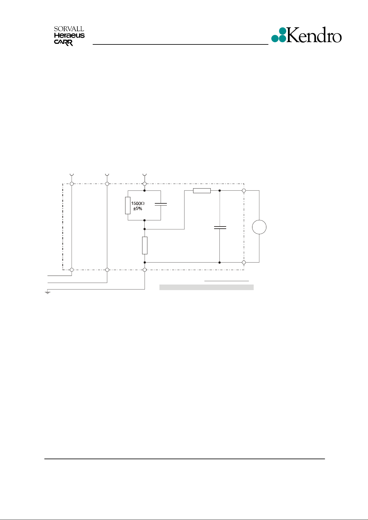
• Accessible current measured to EN 61 010
The accessible current must not exceed 3.5 mAmps in single fault condition (interrupted
protection earth wire)! In accordance with the EN61010, IEC1010 and UL3101 such a fault
condition can be reproduced by the following measuring circuit.
Steckergehäus e / plug-in casing
L (N)
N (L)
PE
500
±1%
Ω
0,22µF
±5%
Ω
Körperstrom:
accessible current:
U = 1750mV I = 3,5mA
10k
±5%
0,022µF
±5%
I [mA] = U [mV] / 500 :
max max
≡
Spezifaktionen für Meßgerät
- TRMS, DC - 5kHz oder mehr
- Eingangswiderstan d > 1M
- Toleranz 5% oder besser
- Crest Faktor 5 oder besser
V
AC
Specifaction for the meter
- TRMS, DC - 5kHz or more
- Input resistance > 1M
- Tolerance 5% or better
- Crest Factor 5 or better
Ω
Ω
Edition: 04 Servicing Schedule
18.04.02/he/AH Page: 2 - 10
Legend RT
Multifuge 3S-R/3L-R
Page 13

3 Functional Description
3.1 Block Functions
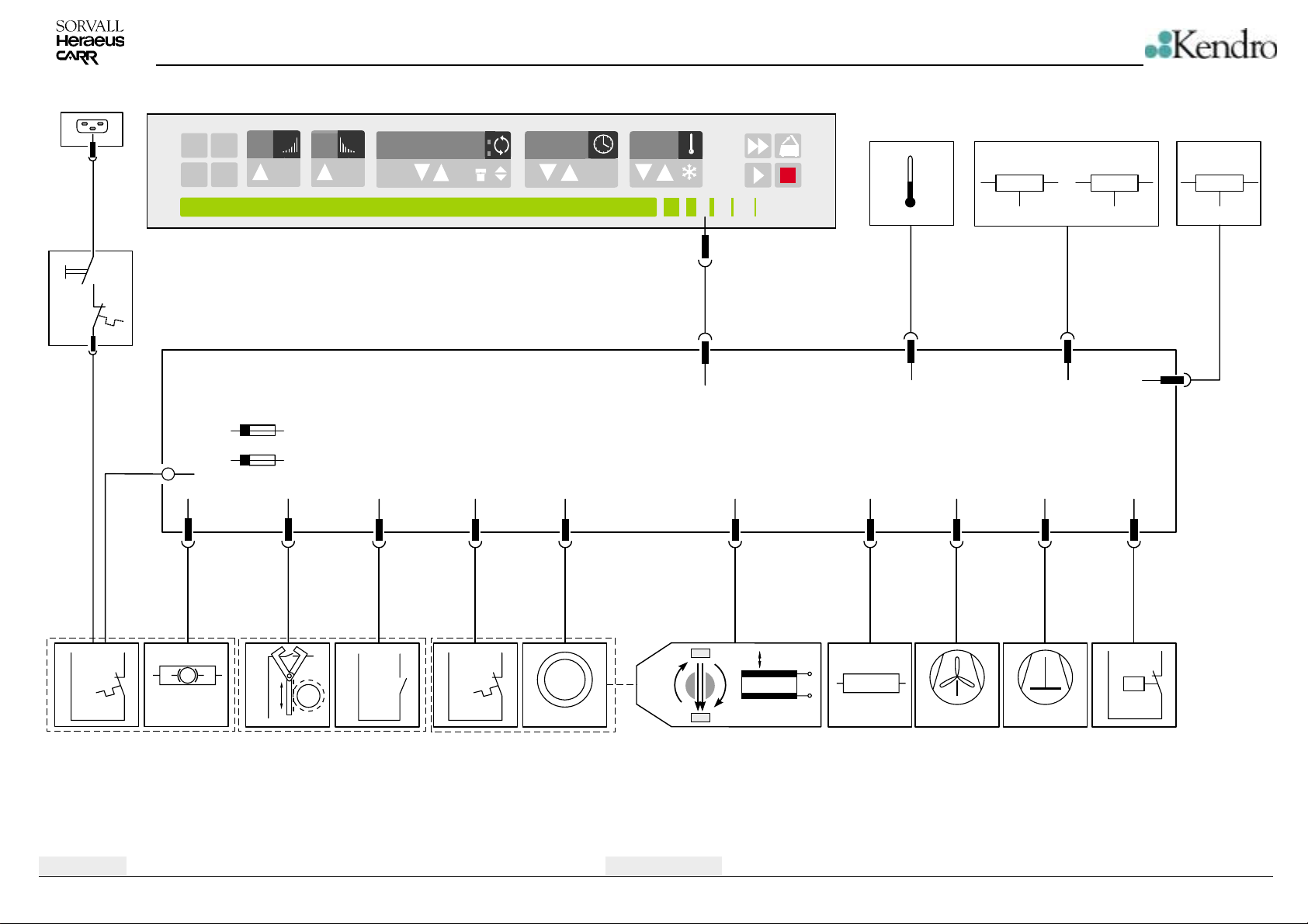
The Multifuge 3L-R/3S-R, Legend RT is a refrigerated microprocessor controlled laboratory
tabletop centrifuge with noise reduced induction drive motor incorporating automatic rotor and
imbalance detection and self-closing door locking systems.
The unit is equipped with following boards and components (block diagram 4-1):
• Instrument socket for mains cable at the back
• Two poles mains switch
• Main board with microprocessor part and power electronics
• Key and indication board (program: EASYCONTROL II with temp. Display or QUICK-CONTROL
with adjusting knob)
• Sensor board with rotor detection sensors
• 3 phase induction motor with integrated thermal over-temperature switch (C. O. 150°C)
• Speed detection and imbalance board with filter attached to the motor’s bottom by screws
• self-closing door locking system (mechanical bolt keeper, motor dis-locking)
• 2 parallel brake resistors mounted on safety chamber (one with overtemp.sensor)
• axial-flow fan for power electronics, motor and chamber
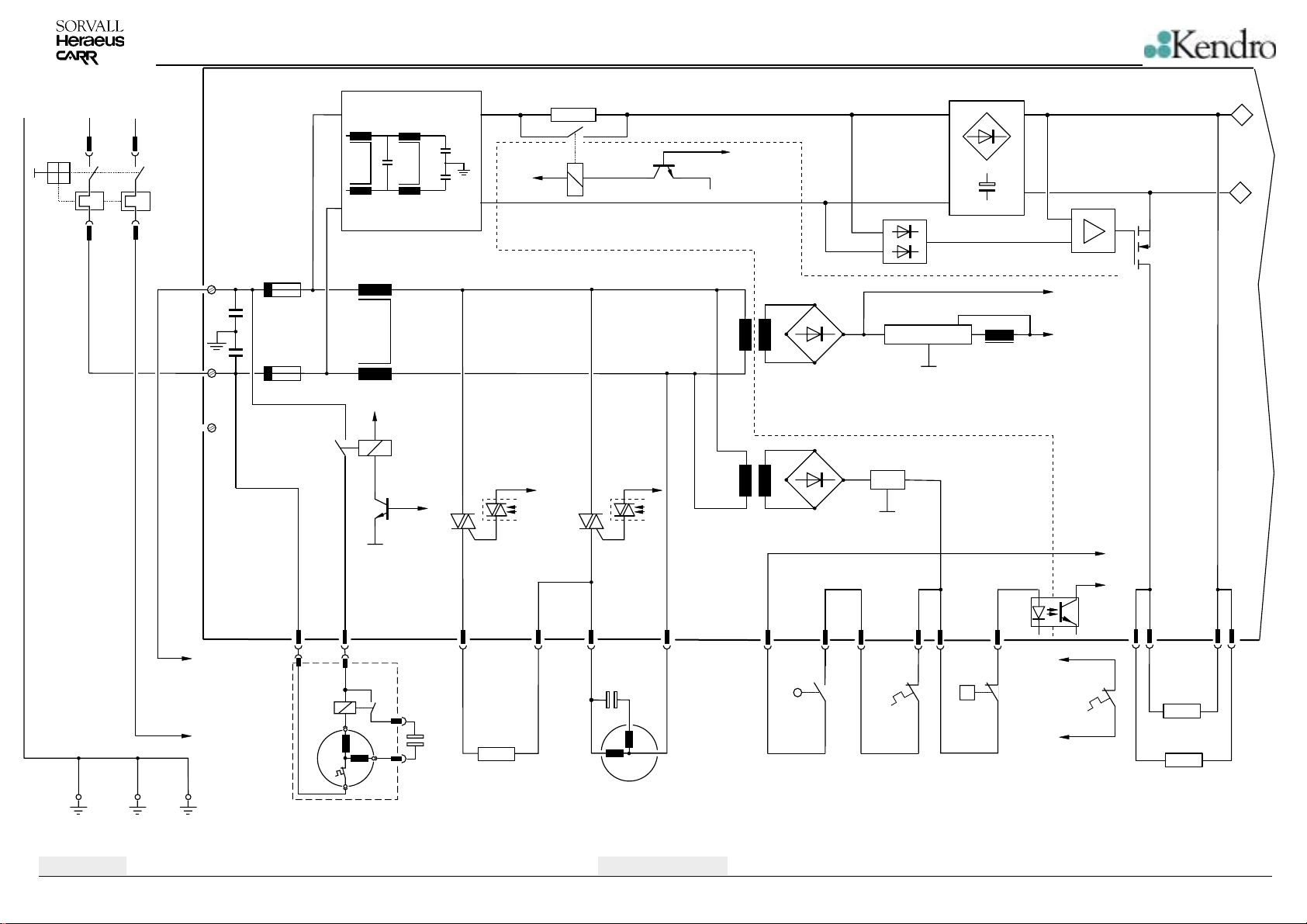
3.2 Main Board Functions
The Main board is mounted at the housing behind the front panel. The components on main
board are arranged in following function blocks (see wiring diagram page 4-2 and 4-3).
• Noise filter in accordance with EN 55011 for motor and triac circuits
• Power pack for low voltage supply of microprocessor part and power electronics
• Triac driving circuits for compressor cut-in relay, for 2 independent fan wiring terminals and for
connection of a heater (special use)
• DC intermediate circuit for supply of frequency converter equipped with automatic loading and
voltage (brake) controlling circuits
• Power part inclusive physically separated driving stages
• Microprocessor part with CPU, E-PROM and NV RAM
• Driving component for self-closing lid lock device
• Interface component for serial RS232 (option)
• Exchangeable NV-Ram and E-PROM containing specific data of the unit
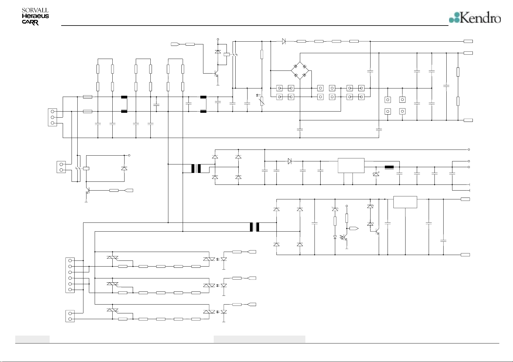
3.2.1 Power Pack
The power pack consists of 2 transformers, 2 rectifiers (single diode) and 2 voltage regulators, which
generates the following low voltage levels:
• U1 = 5V: by switched-mode regulator LM2575T-5.0, VDD, VCC
supplies all processors and its electronic components on main and indication board
• U2 = 24V: unregulated
is used for the driving of lid lock motor and relays K2, K3;
the reference potential is GND, VSS
• U3 = 20V: by 2nd transformer, rectifier diodes and fix voltage regulator 7820
serves for supply of driving of the power electronics via the protection circuit by closed lid
switches
reference potential: 0V CAUTION - MAINS POTENTIAL!
Edition: 03 Servicing Schedule
13.03.01/he Page: 3 - 1
Legend RT
Multifuge 3S-R/3L-R
Page 14

Main Board Functions
3.2.2 Intermediate Circuit
The DC intermediate circuit serves as an energy store between the AC power input and the
transmitted motor performance. The intermediate circuit consists of a heat-sink-cooled bridge
rectifier and several reservoir capacitors which are softly charged across a power resistor R76 when
ever the unit is switched on. After the loading time (CPU initialization time) the power resistor is
linked by the relay contacts of K3. When switching the unit off, the DC voltage of the intermediate
circuit is discharged across a path of resistor R1, R2.
3.2.3 Brake Path
Electrical power is fed back into the intermediate circuit during motor deceleration (motor acts as
generator). This braking power is transformed into heat by two parallel connected resistors so that
the intermediate circuit voltage does not rise to an excessive level. The brake resistors are switched
into the intermediate circuit by a fast switching transistor (pulse-width modulation, synchronized by
the double mains frequency). This transistor is voltage dependent controlled by a self-acting stage
(closed loop).
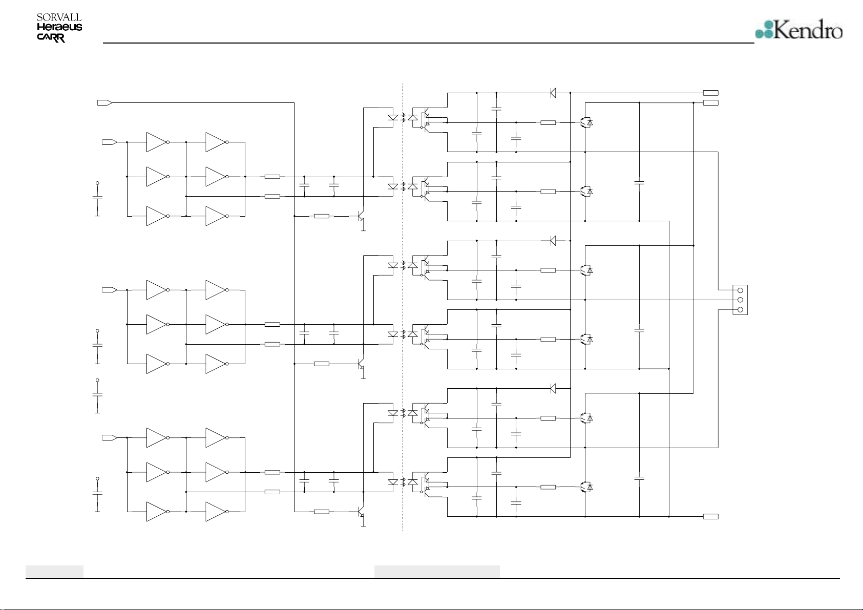
3.2.4 Frequency Converter
The motor is 3-phased, provided with chopped direct voltage blocks (chopped frequency approx.
5kHz, amplitude is height of DC intermediate voltage). These blocks are variable in frequency and
pulse-width modulation, 120° out of phase. These 3 phases are controlled during acceleration,
running at set speed and deceleration (e.g. for small speed: low frequency and small pulse-width
length will be affected). The FC is protected against over current, over temperature and over-voltage.
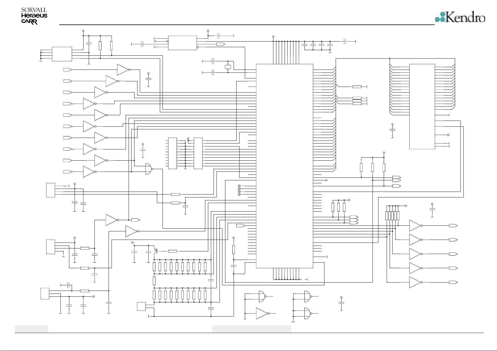
3.2.5 Microcontroller (Central Processing Unit) Part
The software identification No's of the CPU and data storage’s (NV-RAM) ST24C32 are sequentially
displayed in speed and time fields:
Press program place no 2 during switch on
• CPU Operating panel: 526 P05
• Firmware: 528 200
• NV-RAM: 4468 105
The actually indicated version No.'s are displayed in the time field and will be upgraded if program or
data changes are necessary.
The control program (ROM) is integrated in the controller component. The most important operating
parameters (e.g. the maximum data for all rotors, the last operator settings, the basic values for
speed and temperature controlling, data of acceleration and deceleration curves as well as 4 data
sets of program places are stored in the non volatile (NV)-RAM.
When calling this routine the actual value of all centrifugation cycles (“CYL“) is also shown in the
display (as fourth No.) before the check routine for all program places puts an end to the initialization
time (approx. 18s).
The CPU co-operates with the E-PROM component via the 16 bit data bus and some control lines.
The CPU is an integrated circuit, generating all required output signals, monitoring and analyzing all
input signals.
Edition: 03 Servicing Schedule
13.03.01/he Page: 3 - 2
Legend RT
Multifuge 3S-R/3L-R
Page 15
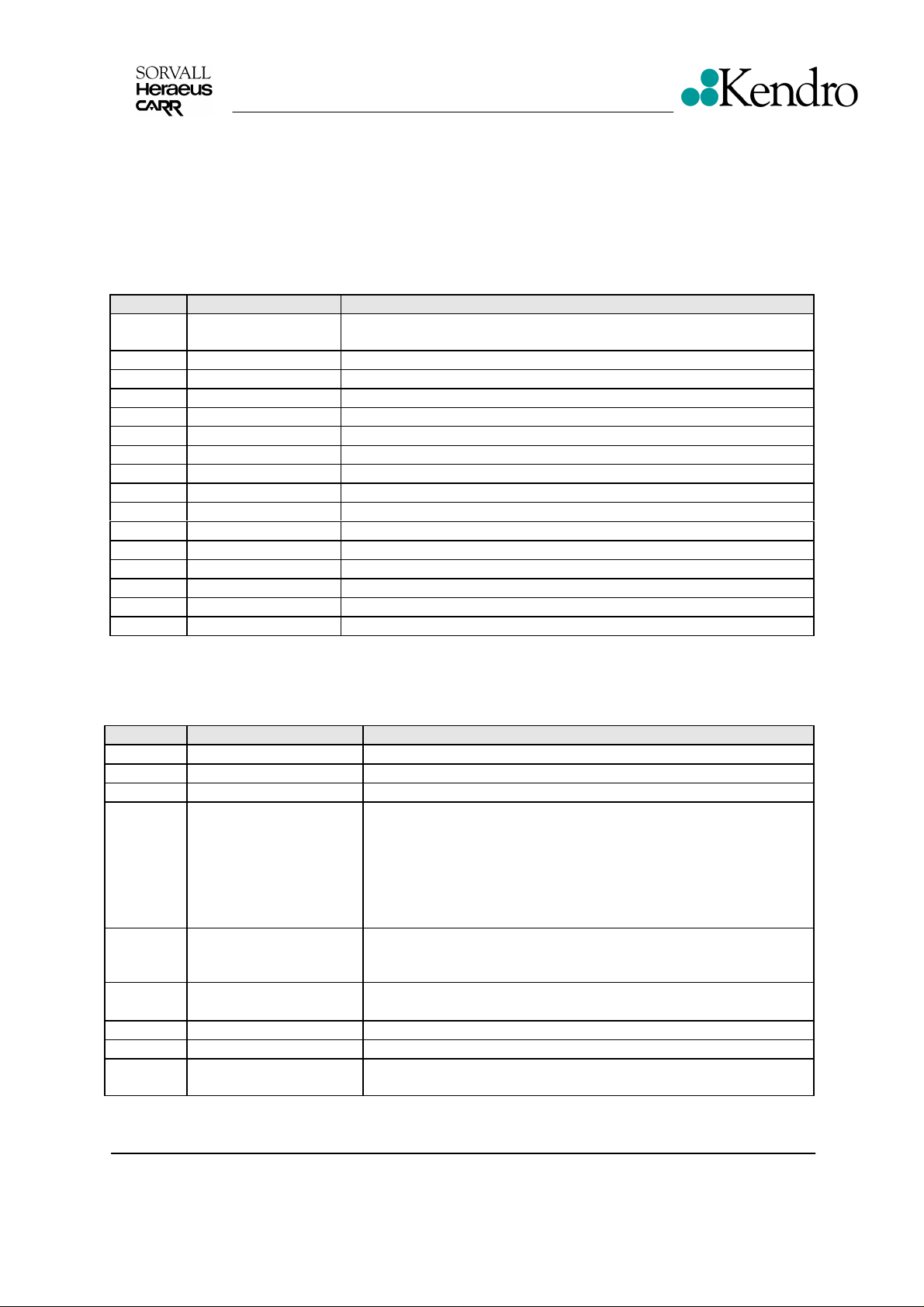
3.3 Key and Indication Board - Easycontrol
The key and indication board is mounted behind the operating panel. The connection to the main
board is done by a 4 pole cable by which the serial data transfer as well as the low voltage supply of
5V is verified. The 7-segment displays, the control LED’s and the operating keys are managed by an
own controller unit (first identification No. 591) in multiplex processing.
For the programming serves EASYCONTROL II (see Operating Instructions).
Functions of keys elements (Easycontrol)
Keys Designation Function(s)
S1 – S4
S5 Arrow up Acceleration profile 1 to 9
S6 Arrow down Deceleration profile 1 to 9
S7 Speed arrow down Decrement the value of the set speed
S8 Speed arrow up Increment the value of the set speed
S9 Bucket Setting of the rotor / bucket number
S10 At the same time Switching between rpm and rcf display
S11 Time arrow down Decrement the value of the set time
S12 Time arrow down Increment the value of the set time
S13 Temp. Arrow down Decrement the value of the set temperature
S14 Temp. Arrow up Increment the value of the set temperature
S15 Frost Pre cooling
S16 Double arrow Quick run – hold button pushed
S17 Lid symbol Open the lid
S18 Arrow right Normal start of the centrifugation
S19 Red square
Program
place 1 to 4
Store or recall programs
Manual stop of a run
Functions of Indicating Elements (Easycontrol)
Indicat. Designation Function(s)
H1 Buzzer Audio signal
H2 Accel. curve digit Display defined acceleration curves 1 to 9
H3 Decel. curve digit Display defined deceleration curves 1 to 9
Speed in rpm (rounded to full 10 rpms)
Rotor not yet detected (xxx „.“)
H4-H7,
H12
H13-H15 Time range
H16,H17 Temperature range
H18 Allocation LED For speed indication
H22 Allocation LED For rcf indication
H19,20,
24,25
Speed range
Rotation Rotor spinning
rcf-value (xg) or not yet possible to calculate „-----“
Identifications no.’s of controller and NV-RAMs,
Lid open condition („OPEn")
Centrifuge run is terminated („End")
Error messages („Lid“, „E-xx“, „bAL“, „rotor“)
Centrifugal time in h.min (count down process)
Count up process (hld) in h.min (count up process)
Actual version number („xx“)
Sample temperature in °C± 2K when pre-cooling or
pre-heating process is terminated
Edition: 03 Servicing Schedule
13.03.01/he Page: 3 - 3
Legend RT
Multifuge 3S-R/3L-R
Page 16
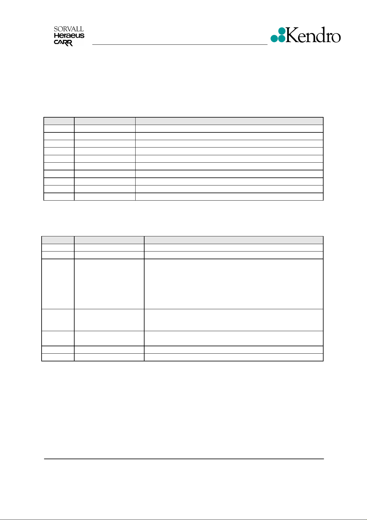
Key and Indication Board - Quickcontrol
The key and indication board is mounted behind the operating panel. The connection to the main
board is done by a 4 pole cable by which the serial data transfer as well as the low voltage supply of
5V is verified. The 7-segment displays, the control LED’s and the operating keys are managed by an
own controller unit (first identification No. 591) in multiplex processing.
For the programming serves Knob control system Quickcontrol (see Operating Instructions)
Functions of keys elements (Quickcontrol)
Keys Designation Function(s)
S1 Adjusting knob Set point temperature
S2 Adjusting knob Set point time
S3 Adjusting knob Set point speed
S6 Arrow up Deceleration profile 1 to 3
S9 Bucket Setting of the rotor / bucket number
S10 At the same time Switching between rpm and rcf display
S16 Double arrow Quick run – hold button pushed
S17 Lid symbol Open the lid
S18 Arrow right Normal start of the centrifugation
S19 Red square
Functions of Indicating Elements (Quickcontrol)
Manual stop of a run
Indicat. Designation Function(s)
H1 Buzzer Audio signal
H3 Decel. curve digit Display defined deceleration curves 1 to 3
Speed in rpm (rounded to full 10 rpms)
Rotor not yet detected (xxx „.“)
H4-H7,
H12
H13-H15 Time range
H16,H17 Temperature range
H18 Allocation LED For speed indication
H22 Allocation LED For rcf indication
Speed range
rcf-value (xg) or not yet possible to calculate „-----“
Identifications no.’s of controller and NV-RAMs,
Lid open condition („OPEn")
Centrifuge run is terminated („End")
Error messages („Lid“, „E-xx“, „bAL“, „rotor“)
Centrifugal time in h.min (count down process)
Count up process (hld) in h.min (count up process)
Actual version number („xx“)
Sample temperature in °C± 2K when pre-cooling or
pre-heating process is terminated
Edition: 03 Servicing Schedule
13.03.01/he Page: 3 - 4
Legend RT
Multifuge 3S-R/3L-R
Page 17

3.4 Speed Detection Board
On a small board, which is attached underneath the motor, the circuits for speed detection and signal
shaping are arranged. The motor speed is optically detected by an infra-red light barrier. The motor
axle has a hole at the same level as the light barrier. This effects that the light beam will be
interrupted twice during one motor revolution. A following pulse shaping stage on board forms
square-topped pulses which are led via XW1 to the main board. The speed pulses are counted by
the CPU to display the exact motor speed.
3.5 Rotor Indication
In the rotor’s bottom 4 magnets are forced, being alternately arranged in polarity and positioned to
each other to different distances on a constant circular ring (segment steps of 20°).
A Hall sensor is exactly fixed below to the sensor board. The magnets are switching a flip-flop stage
by which different pulse lengths and pulse intermissions are generated during one rotor rotation. By
this signal the CPU is able to detect up to 65 different rotors and the correct direction of rotation, too.
3.6 Imbalance Detection
On the speed detection board a piezoelectric acceleration detector is additional fixed. Dependent of
the rotor imbalance this sensor generates an analogous voltage signal which is led via a following
band-pass filter to plug connection XW1/2 to main board, where it is analysed by CPU. When the
CPU) has identified the installed rotor type, the speed dependent imbalance limitation curve from EPROM The analogue imbalance signal is filtered, converted into digital form and continuously
comperated with this specific limitation curve. If the actual imbalance signal will rise at any speed
beyond the limit, the error signal for imbalance load “bAL“ will be displayed and the unit slows down.
3.7 Lid lock system
The latch is directly controlled by CPU via a PWM motor driver. If all necessary signals are existing
which allow an opening the motor is fired with a pulsed voltage of 24 VDC. For additional safety the
relay K2 will be activated if the speed is below 120 rpm controlled by triggered mono-flops.
3.8 Cooling plant
The Multifuge 3SR/LR, Legend RT is equipped with a high-grade cooling plant, to meet it’s
requirements of driving power and compact design. The CFC free refrigerant R404A evaporates at
low temperatures (≤ -20°C) and absorbers through this the frictional heat from chamber produced by
the fast spinning rotor. 5 fans serve for even air flow through condenser so that the refrigerant’s
condensing temperature is kept on a low level (lateral front fans are only switched on, if n > 0 rpm).
A specially designed coaxial heat exchanger serves for essential undercooling of the condensed
refrigerant to ensure an optimum evaporation and a perfect operation of the expansion valve. To
maintain low evaporation and resultant condensation temperatures on one hand and to support the
starting procedure of the compressor on other hand, a thermostatic expansion valve with 3.0bara
MOP is used.
The minimum achievable sample temperatures are depending on speed, rotor type and a little on
ambient temperature. After a compensating time, given by the pre-cooling or pre-heating program as
optimal result, the rotor has reached the selected set temperature within a tolerance of ± 2K.
To reduce the power consumption of the unit the compressor will not be activated during
accelerating of the motor. When reaching the selected speed the compressor will be activated if a
low temperature had been selected.
Edition: 03 Servicing Schedule
13.03.01/he Page: 3 - 5
Legend RT
Multifuge 3S-R/3L-R
Page 18
Unit's Plug
SCHEMATIC DIAGRAMS
132
0 0
4
SORVALL
S0
Mains Switch with Over-current Release
16A
X4
P/L/PE
XD1
D
®
F1
F2
LEGEND
X13
+/-
rpm
x g
xg
RT
KEY AND INDICATION BOARD
MAIN BOARD
X20
A
X20
B
X122
1/2/3
X11
C
XI
XW1
W
Temp. Sensor
PT
V1
100
X5
U
X12
M
Sensors for Lid Lock
X12
V
X17
G
X14
C
Rotor Detection
XXX
XR1
R
X20
P
Overtemp.
Edition: 04
04.07.02 AH
F3F4 F5
M4
R2 R3
R1
S1
Lid Lock SwitchBrake ResistorBrake Resistor
Overtemp. SwitchLid Lock
Motor
3~
M1
Motor
Speed Detection
2 Pulses/revolution
Imbalance Sensor
a(t)
Block Diagram
4-1
Resistor for
Speed Limit
Compressor
Fan
M3
Fan for
Compressor
p>
M2
Compressor
Pressure Switch
Multifuge 3S-R / 3L-R / Legend RT
Page 19
16A
S0
Mains
NPE
120V
SCHEMATIC DIAGRAMS
L
4R7 11W
DC Intermediate Circuit
noise filter
+24V
K3
DC Charging Circuit
BYPASS
Autom. Brake Control
X4/L
+24V
F1
+5V
(VCC)
(VDD)
X4/N
F2
+24V
LM2575T-5.0
GND
VSS
+325V
1
0V
2
MAIN BOARD
X4/PE
K1
Chassis
Edition: 04
04.07.02 AH
Ground Motor
COOLING
GND
X17/G
2
1
M2
10
Î
11
13
14
Compressor
with Starting Relay
X12/M
4
C
S
240µF
Speed Reduction
R3
FAN2
FAN1
X12/V
3
2
4,0µF
1
C
L
XA2
S1
M3
Fan for CondenserResistor for
Lid Lock Switch
7820
0V
X20/B
4
3
F3
Motor
Overtemp.
X20/P
2
1
21bar
p>
F5
Overpressure
Switch
+20V
OVERPRESSURE
XD1/R
13
24
R1
F4
2 x 120W
R2
Brake Resistors with
Overtemperature Protector
Wiring Diagram
4-2
Multifuge 3S-R / 3L-R / Legend RT
Page 20
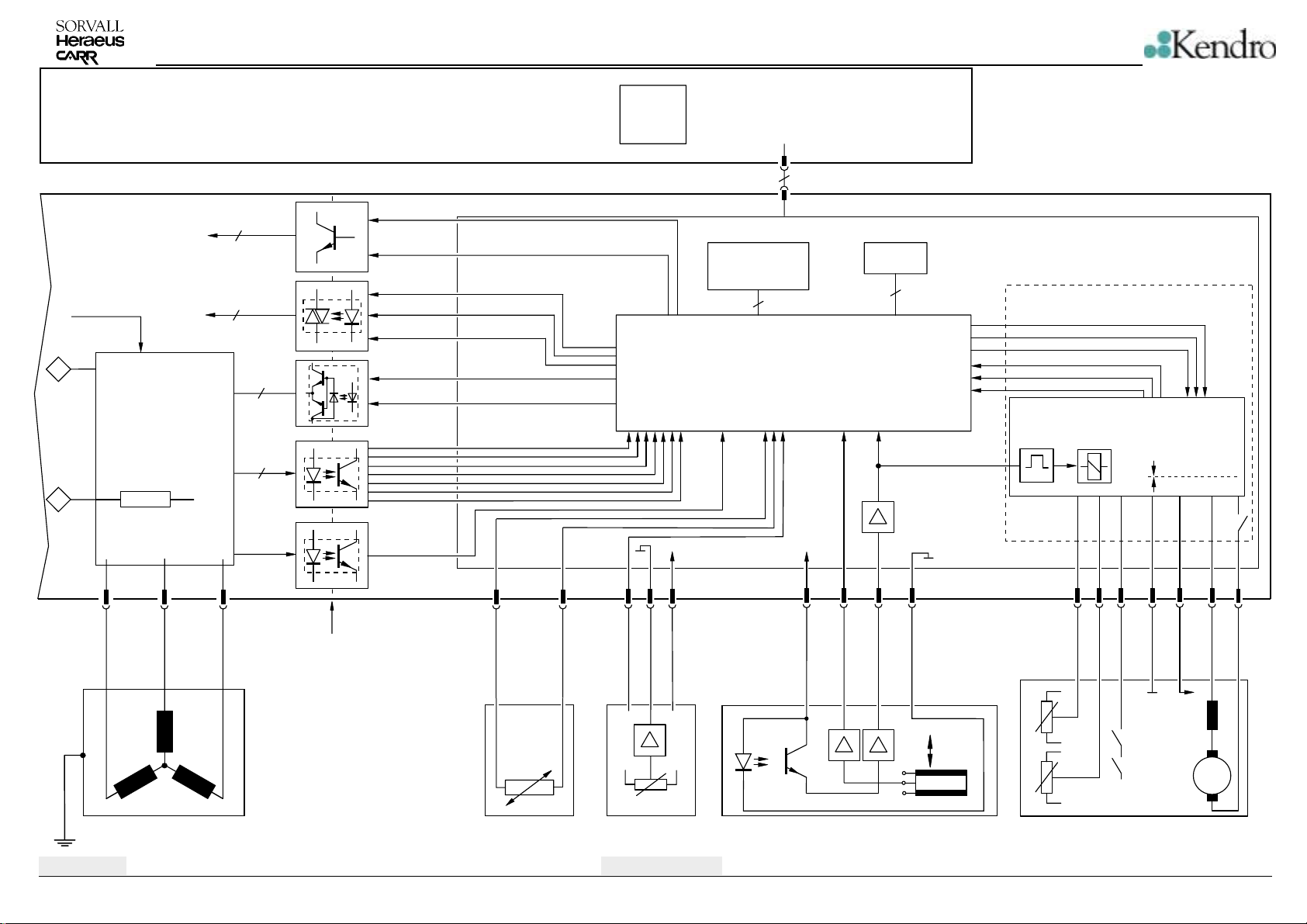
SCHEMATIC DIAGRAMS
KEY AND INDICATION BOARD
MAIN BOARD
20V
+325V
1
Frequency Converter
0V
2
Current Control Restistor
X122/
1
20V
2
2
3
0V*
3
µC87C54
EASYCONTROL II
0526Vxx
5V
GND
XI
4
XI
COOLING (M2)
K3 (BYPASS)
0528Vxx
Fan1 (M3)
Fan2 ()
Heating ()
3
7
6 IGBT’s
RESET
LID_CLOSED
OVERVOLTAGE
OVERCURRENT
MOTOR_OVERTEMP.
ELECTRONIC_OVERTEMP.
OVER_PRESSURE
POWER_FAIL
36
CPU
NV-RAMEPROM
4467Vxx
4
µP - Part
LID_LOCK_BRAKE
LID_LOCK_ENABLE
LID_LOCK_DIRECTION
LID_NEARLY_CLOSED
LID_LOCK_CLOSED
LID_LOCK_OPEN
K2
24V
1s
5V
GND
24V
Lid Lock Driving
in:
+
out:
-
+
K2
i
dyn
X5/U1
X5/U2
XR/ 1 2 3
+5V +5V
GND
GND
1
XW/ X14/ 3 5 7
2
234
1
X13/
-
+
Edition: 04
04.07.02 AH
M1
Motor
3 x 2,5
Physical Separation
W
V1
PT100
J
Temperature Sensor
X
Hall Effective Sensor
Wiring Diagram
4-3
n=0:
n>0:
Speed Detection Board
a(t)
+5V
GND
X
X
M4
Lid Locking Device with
Switches and Sensors
Multifuge 3S-R / 3L-R / Legend RT
Page 21
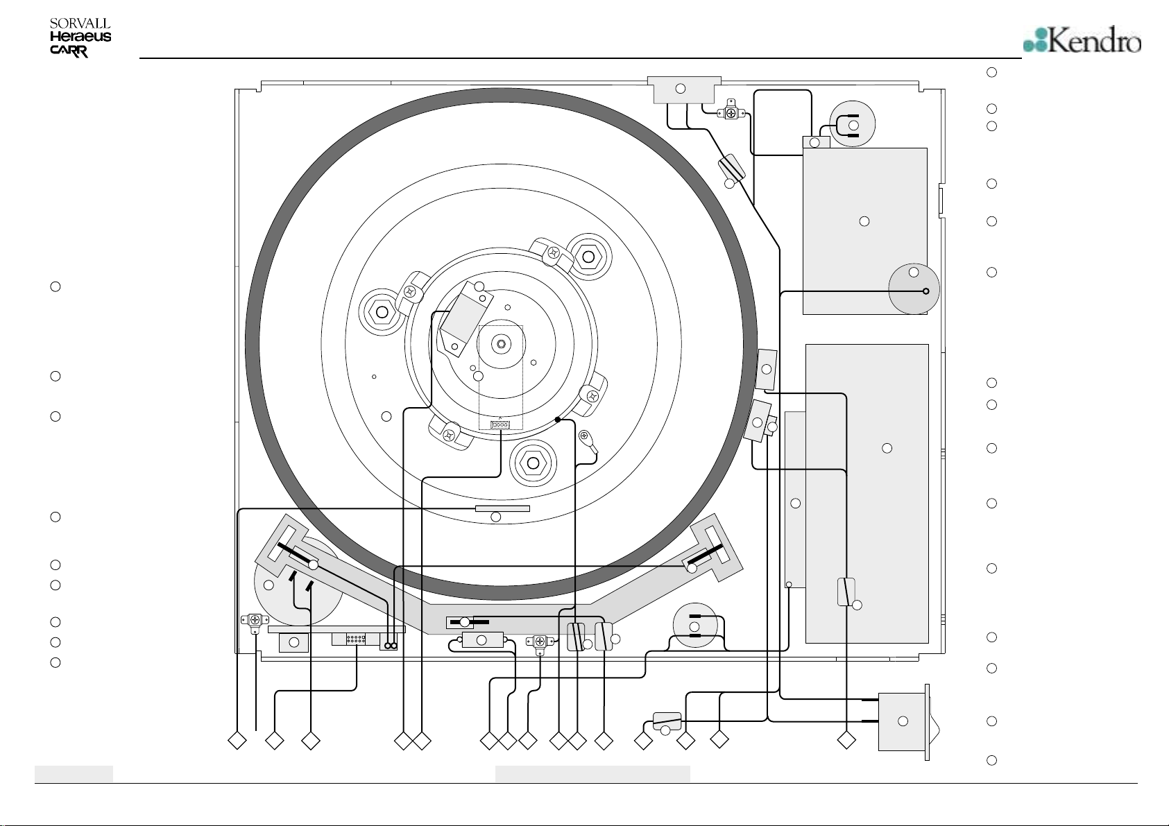
SCHEMATIC DIAGRAMS
Mains Input
10
10
Start Capacitor
12
12
13
13
Relay for Compressor
PCB Rotor Detection (fill up)
1
PCB Speed and Imbalance Detection
2
( under the motor)
Motor
3
Pt100 Temperature Sensor
4
Switch at the left Lid Lock
5
Motor for Lid Lock
6
Switch Lid Lock
7
PCB Sensors for Lid Lock
8
Resistor for Fan
9
Edition: 04
04.07.02 AH
14
15
16
1
2
3
5
-
6
+
8
1
2
3
5
4
XW1
4
21
7
9
11
7
8
10
25
23
9
12
6
22
25
13
14
17
17
18
19
20
25
Line
Out
24
15
Toroidal Core with
14
2 electrical windings
Compressor
15
Over Pressure Switch
16
17
Brake Resistor
18
Temperature Fuse
Condenser
19
Fan for Condenser
20
Switch at the right lid lock
21
Capacitor for Fan
22
Toroidal Core with
23
2 electrical windings
24
Mains Switch
Toroidal Core with
25
1 electrical winding
Wiring Connections Diagram
4-4
Multifuge 3S-R / 3L-R / Legend RT
Page 22
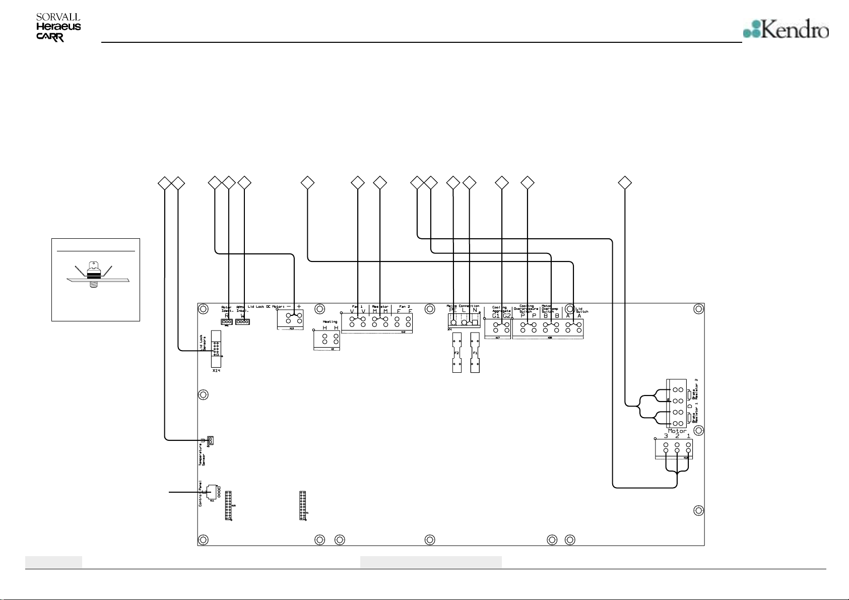
Temperature Sensor
PCB sensors for Lid Lock
Motor for Lid Lock
PCB Rotor Detection
PCB Speed and Imbalance Detection
Switch Lid Lock
SCHEMATIC DIAGRAMS
Fan for Condenser
Resistor for Fan
Motor
Over Temperature Switch Motor
PE - Terminal
Mains Input
Compressor
Over Pressure Switch
Brake Resistors
Mounting of Unit Ground
1x PE terminal 3 pole
1x screw M4x10mm
2x fan washer 4,3mm
12
34 5 6 7 8 910 1112 13 14 15
XW1
MAIN BOARD
Edition: 04
04.07.02 AH
Key- and Indication Board
Wiring Connections Diagram
4-5
Multifuge 3S-R / 3L-R / Legend RT
Page 23
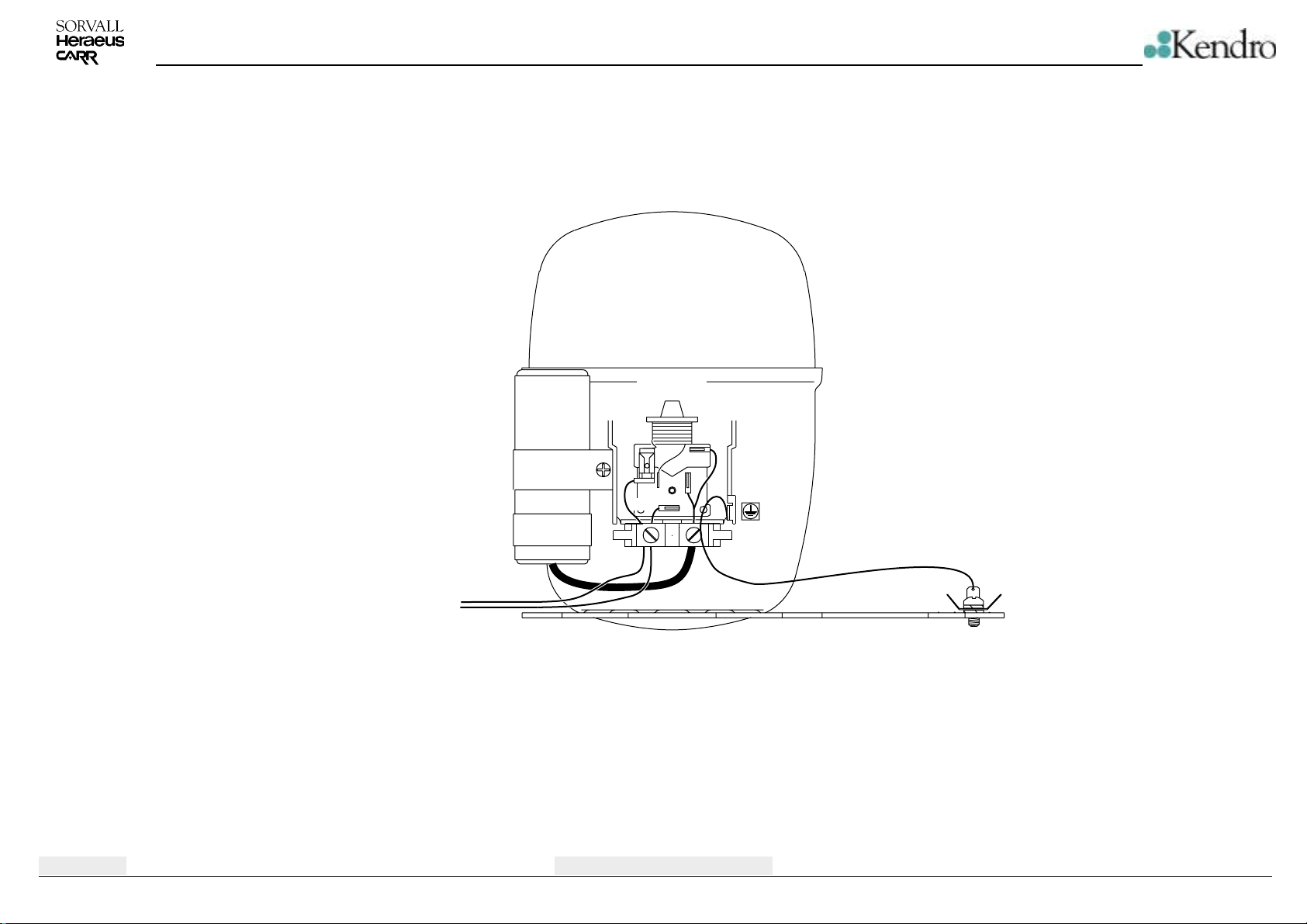
SCHEMATIC DIAGRAMS
Connection Diagram Compressor
Compressor
Main Board G2, black
Main Board G1, white
Starting
Capacitor
Starting Relay
10
BLK
12
WHT
11
13
14
grn yel
Edition: 04
04.07.02 AH
Wiring Connections Diagram
4-6
Multifuge 3S-R / 3L-R / Legend RT
Page 24
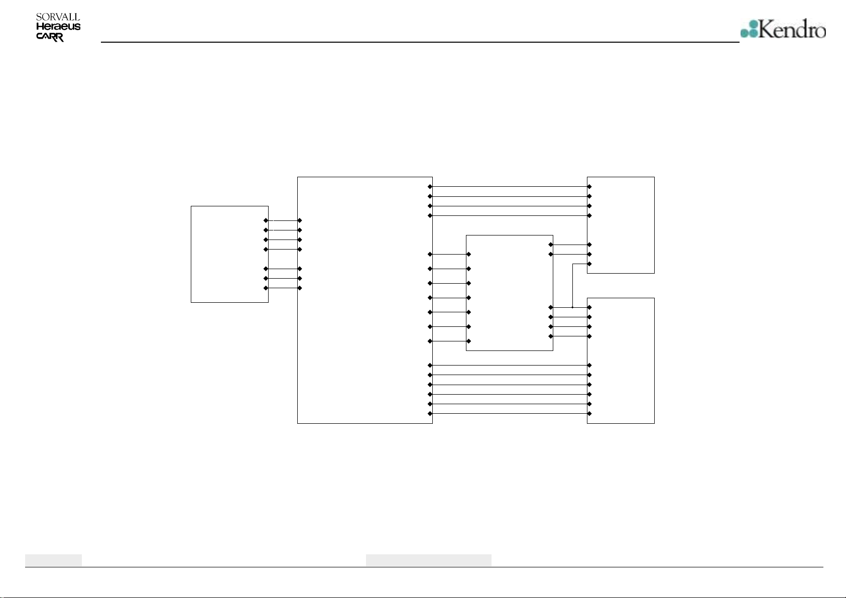
SCHEMATIC DIAGRAMS
Lid Lock Control
B06
/LID_LOCK_ENABLE
/LID_LOCK_BRAKE
LID_LOCK_DIRECTION
RPM_PULSE
/LID_NEARLY_CLOSED
/LID_LOCK_CLOSED
/LID_LOCK_OPEN
Controller
/LID_LOCK_ENABLE
/LID_LOCK_BRAKE
LID_LOCK_DIRECTION
RPM_PULSE
/LID_LOCK_CLOSED
/LID_LOCK_OPEN
H04
RESET
/PHASE1
/PHASE2
/PHASE3
ELECTRONIC_OVERTEMP
CURRENT/LID_NEARLY_CLOSED
/OVERCURRENT
/OVERVOLTAGE
OVER_PRESSURE
MOTOR_OVERTEMP
/LID_CLOSED
FAN1
FAN2
COOLING
HEATING
BYPASS
POWER_FAIL
Protection Circuits
ELECTRONIC_OVERTEMP
CURRENT
/OVERCURRENT
/OVERVOLTAGE
OVER_PRESSURE
/LID_CLOSED
C05
+20V_switched
+325V
Inverter
RESET
/PHASE1
/PHASE2
/PHASE3
+20V_switched
0V*
ZK2
+20VMOTOR_OVERTEMP
0V
0V*
+325V
B03
Supply
+325V
ZK2
+20V
0V
FAN1
FAN2
COOLING
HEATING
BYPASS
POWER_FAIL
C02
Edition: 04
04.07.02 AH
Main Board 184 Overview
4-7
Multifuge 3S-R / 3L-R / Legend RT
Page 25
SCHEMATIC DIAGRAMS
Mains
Connection
N
L
PE
Phoenix-Klemme
Cooling
Aggregate
Fan 2
Resistor for Fan
Speed Reduction
Fan 1
Heating
X4
G1
G2
WAGO 256-602
3
2
1
X17
1
2
X12
F
F
M
M
V
V
WAGO 256-606
X2
H
H
WAGO 256-602
6
5
4
3
2
1
1
2
8
6
4
2
GND
F2
SI 15AT
F1
SI 15AT
C7
4n7
Y
10
1
2xS T92S7D12-24
K1
REL24V
V12
BC817-25
SMD
R8
22k
SMD
R9
22k
SMD
C6
4n7
Y
V11
V21
V22
R121 1k SMD
R7
22k
SMD
R6
22k
SMD
24
1
3
L5
2x2.1mH
16A
+24V
V23
LL4148
SMD
R17
4k7
SMD
R26 1k SMD
R60 1k SMD
COOLING
T835-600B
T835-600B
T835-600B
R19
100R
SMD
R27
100R
SMD
R61
100R
SMD
L1
2x2.1mH
16A
V20
LL4148
SMD
V26
BC817-25
SMD
+24V
R76
4R7
6
2
1
4
10
GND
C10
1u5
X
3
V5
1N5404
V2
1N5404
Bauhöhe beachten
6
4
6
4
6
4
R24
1
220R SMD
D1
S21ME4
2
GND
R31
1
220R SMD
D2
S21ME4
2
GND
R25
1
220R SMD
D3
S21ME4
2
GND
K3
8
REL24V
2xS T92S7D12-24
C63
1u5
X
11W
C3
1u5
X
V10
1N5404
C13
470u
50V
V6
1N5404
T2
120V / 24V 3.2VA
FAN2
FAN1
HEATING
R4
V130LA20A
VDR
BYPASS
R53
4k7
SMD
R123
R124
22k
22k
SMD
SMD
R122
R125
22k
22k
SMD
SMD
C49
1u5
X
C112
C82
10n
10n
Y
Y
R20
100R
SMD
R28
100R
SMD
R62
100R
SMD
R127
22k
SMD
R126
22k
SMD
R21
100R
SMD
R29
100R
SMD
R63
100R
SMD
R128
22k
SMD
R129
22k
SMD
24
C48
1u5
X
1
T1
120V / 18V 16VAmit PTC
R22
100R
SMD
R30
100R
SMD
R64
100R
SMD
V7
R10
SM4007
100R
SMD
SMD
~
BR2
12
BR6
12
U
120V only 230V only
V24
C1
100n
SMD
V14
SM4007
SMD
V13
SM4007
SMD
SM4007
SMD
+
R13
R12
R11
100R
100R
100R
SMD
V48
FAGOR FB2506L
+
with heat sink SK 09 37,5 SA K
SMD
SMD
~
-
BR3
12
BR7
12
C14
10n
Y
47-58kHz 5V +/- 4%
C106
+
470u
C107
100n
50V
SMD
V1
V16
SM4007
ZMM18
SMD
C19
470u
50V
V15
SM4007
SMD
R5
4k7
+
SMD
BR1
12
BR5
12
120V only
D12
LM2575T-5.0
1
+VIN
OUT
GND
OFF
3
5
V53
VCC
ZMM18
R14
10k
SMD
V54
ZMM18
POWER_FAIL
3
1
U1
SFH6106-3
4
2
SMD
GND
C4
220n
400V
C15
10n
Y
4
FB
2
V25
1N5822
V52
BD243
L4
330uH
2
1
BR4
230V
only
V18 7820
2
C16
100n
SMD
VI
Auxilary Intermediate Circuit
2
BR8
230V
only
1
C109
+
100u
40V
VO
GND
1
Intermediate Circuit
+
C84
1000u
200V
C81
1000u
200V
+
120V 120V
only
C108
100n
SMD
3
C2
100u
40V
ZK2
+325V
+
C83
1000u
200V
C8
1000u
200V
+
only
C110
100n
SMD
C17
100n
SMD
+
R2
150k
SMD
C12
1u5
X
R1
150k
SMD
0V
+24V
VDD
VCC
C111
100n
SMD
GND
VSS
+20V
0V
Edition: 04
04.07.02 AH
Main Board 184 - Power Supply
4-8
Multifuge 3S-R / 3L-R / Legend RT
Page 26
RESET
/PHASE1
/PHASE2
/PHASE3
SCHEMATIC DIAGRAMS
All IGBT's with heat sink:
V29
D5
2
D10C
56
74HC14
SMD
D10B
VCC
C98
100n
SMD
GND
VCC
C97
100n
SMD
GND
VCC
C25
+
10u
SMD 25V TA
GND
VCC
C96
100n
SMD
GND
34
74HC14
SMD
D10A
12
74HC14
SMD
D9C
56
74HC14
SMD
D9B
34
74HC14
SMD
D9A
12
74HC14
SMD
D8C
56
74HC14
SMD
D8B
34
74HC14
SMD
D8A
12
74HC14
SMD
D10D
98
74HC14
SMD
D10E
11 10
74HC14
SMD
D10F
13 12
74HC14
SMD
D9D
98
74HC14
SMD
D9E
11 10
74HC14
SMD
D9F
13 12
74HC14
SMD
D8D
98
74HC14
SMD
D8E
11 10
74HC14
SMD
D8F
13 12
74HC14
SMD
R59
120R SMD
R58
120R SMD
R57
120R SMD
R56
120R SMD
R55
120R SMD
R54
120R SMD
T=2.5us
T=2.5us
T=2.5us
C104
0n
SMD
C103
0n
SMD
C102
0n
SMD
R120
4k7
SMD
R119
4k7
SMD
R117
4k7
SMD
C101
22n
SMD
Folie
C100
22n
SMD
Folie
C99
22n
SMD
Folie
3
D4
2
3
V37
BC817-25
GND
D14
2
3
D13
2
3
V9
BC817-25
GND
D36
2
3
D35
2
3
V8
BC817-25
GND
HCNW3120
HCNW3120
HCNW3120
HCNW3120
HCNW3120
HCNW3120
8
7
6
5
C31
100n
SMD
8
7
6
5
C33
100n
SMD
8
7
6
5
C34
100n
SMD
8
7
6
5
C35
100n
SMD
8
7
6
5
C32
100n
SMD
8
7
6
5
C36
100n
SMD
C28
100u
+
SMD 25V
C55
100u
+
SMD 25V
C29
100u
+
SMD 25V
C54
100u
+
SMD 25V
C30
100u
+
SMD 25V
C50
100u
+
SMD 25V
BA159
R33
15R
C43
SMD
0n
SMD
R34
15R
C38
SMD
0n
SMD
V28
BA159
R35
15R
C39
SMD
0n
SMD
R36
15R
C40
SMD
0n
SMD
V27
BA159
R37
15R
C41
SMD
0n
SMD
R38
15R
C42
SMD
0n
SMD
KUNZE KU 3-315/SO/VE
V35
IXGH20N60BU1
V33
IXGH20N60BU1
V34
IXGH20N60BU1
V32
IXGH20N60BU1
V31
IXGH20N60BU1
V30
IXGH20N60BU1
C105
100n
400V
C88
1u5
X
C89
1u5
X
+20V_switched
+325V
1
2
3
0V*
X122
WAGO 256-603
3
2
1
Motor
Edition: 04
04.07.02 AH
Main Board 184 - Inverter
4-9
Multifuge 3S-R / 3L-R / Legend RT
Page 27
SCHEMATIC DIAGRAMS
NVRAM IIC
with DIP 8 Socket
GND
/LID_NEARLY_CLOSED
/LID_LOCK_CLOSED
/LID_LOCK_OPEN
OVER_PRESSURE
MOTOR_OVERTEMP
ELECTRONIC_OVERTEMP
/OVERVOLTAGE
/OVERCURRENT
Control Panel
C
BURNDY 4POL
RPM and
Imbalance
Sensors
W
BURNDY 4POL
Rotor
Identification
XR1
R
Burndy 3pol
Edition: 04
04.07.02 AH
1
2
3
POWER_FAIL
/LID_CLOSED
X11
1
2
3
4
abgew.
XW1
1
2
3
4
1
1
2
2
3
3
D15
E0
E1
E2
VSS4SDA
ST24E16
GND
1
2
3
4
1
2
3
4
GND
GND
GND
VCC
/WC
SCL
D29D
VCC
C44
100n
SMD
GND
VCC
GND
C11522p
C78
100n
SMD
GND
C69
100n
8
SMD
7
6
5
GND
D26B 74HC14 SMD
D26C 74HC14 SMD
56
98
13 12
13 12
D16F 74HC14 SMD
12
D29A 74HC14 SMD
11 10
D16E 74HC14 SMD
56
D29C 74HC14 SMD
34
D29B 74HC14 SMD
C23
10u
+
SMD 25V TA
GND
R100
10k
SMD
C77
100n
SMD
GND
R103
22k
SMD
GND
R101
10k SMD
VCC
C24
10u
+
SMD 25V TA
GND
R104
R107
4k7
4k7
SMD
SMD
D26A 74HC14 SMD
12
34
74HC14 SMD
D29F
74HC14 SMD
D26E
74HC14 SMD
11 10
C27
C60
10n
SMD
C62
100n
SMD
10u
SMD 25V TA
C61
10n
SMD
GND
GND
C56
2u2
D26D
+
GND
PT100
Temperature
Sensor
U
GND
74HC14
X5
+
GND
VCC
GND
VCC
C86
100n
SMD
U4A
2
3
74HC02
RPM_PULSE
C64
100n
SMD
GND
R90
100R
0.1%
1
1
2
2
GND
VCC
SMD
GND
SMD 20V TA
98
VCC
BURNDY 2POL
Reset Controller
1
2
3
4
C75
100n
SMD
Electronic Overtemperature active L
RPM Signal
Overvoltage active H
Motor Overtemp active L
Lid closed Signal active H
Overcurrent active H
Interface Module
1
3
5
7
9
11
13
15
17
19
1
Q1
BC807
R134-R143
D25
CONTROL
RESIN
CT
GND
TLC7705I
X15
+
+
+
+
+
+
+
+
+
+
+
+
+
+
+
+
+
+
+
+
CON20
R40
100R SMD
R95
100R
SMD
R99
4k7 SMD
2
4
6
8
10
12
14
16
18
20
VCC
GND
GND
1R0 SMD
1R0 SMDR145-R154
SENSE
RESET
RESET
11
13
15
17
19
VCCVCC
C5
8
VDD
7
6
5
C58
22p SMD
GND
C59
22p SMD
GND
SCL
SDA
X16
2
1
/RESOUT
+
+
4
3
/IRQ
+
+
6
5
SCLK
+
+
8
7
DETECT0
+
+
10
9
DETECT1
+
+
12
+
+
14
+
+
16
/CS
+
+
18
DOUT
+
+
20
DIN
+
+
CON20
C57
1n
SMD
C73
10n
SMD
C74
10n
SMD
100n SMD
RESET
5.0 MHz
J1
TP1
TP2
TP3
TP4
PT100 on/off
GND
AD0 Temp.
AD1 Temp.
AD2 Temp.
AD3 Temp.
Imbalance
CURRENT
VCC
R102
10R
SMD
C70
100n
SMD
GND
138
137
140
141
84
47
48
49
50
51
52
53
54
57
58
59
60
61
62
63
64
65
66
67
68
69
70
73
74
75
76
77
78
79
80
81
10
11
12
13
14
15
16
27
28
29
30
31
32
33
34
35
36
39
40
41
42
43
44
37
38
SAB80C167CR-LM
SMD
13 12
9
D30
XTAL1
XTAL2
/RESIN
/RESOUT
VPP
P2.0
P2.1
P2.2
P2.3
P2.4
P2.5
P2.6
P2.7
P2.8
P2.9
P2.10
P2.11
P2.12
P2.13
P2.14
P2.15
P3.0
P3.1
P3.2
P3.3
P3.4
P3.5
P3.6
P3.7
P3.8
P3.9
P3.10/TXD0
P3.11/RXD0
P3.12//BHE
P3.13
P3.15
P8.0
P8.1
P8.2
P8.3
P8.4
P8.5
P8.6
P8.7
P5.0
P5.1
P5.2
P5.3
P5.4
P5.5
P5.6
P5.7
P5.8
P5.9
P5.10
P5.11
P5.12
P5.13
P5.14
P5.15
VAREF
VAGND
5
6
U4B
74HC02
D26F
4
74HC14
SMD
VCC
82
72
56
46
17
VCC
VCC
VCC
VCC
GND
GND
GND
GND
83
71
55
45
18
C65
C66
C67
100n
100n
SMD
SMD
144
136
126
109
93
VCC
VCC
VCC
VCC
VCC
VCC
GND
GND
94
P0L0
P0L1
P0L2
P0L3
P0L4
P0L5
P0L6
P0L7
P0H0
P0H1
P0H2
P0H3
P0H4
P0H5
P0H6
P0H7
P1L0
P1L1
P1L2
P1L3
P1L4
P1L5
P1L6
P1L7
P1H0
P1H1
P1H2
P1H3
P1H4
P1H5
P1H6
P1H7
P4.0/A16
P4.1/A17
P4.2/A18
P4.3/A19
P4.4/A20
P4.5/A21
P4.6/A22
P4.7/A23
P6.0//CS0
P6.1//CS1
P6.2//CS2
P6.3//CS3
P6.4//CS4
P6.5//HOLD
P6.6//HLDA
P6.7//BREQ
P7.0
P7.1
P7.2
P7.3
P7.4
P7.5
P7.6
P7.7
/RD
/WR//WRL
/READY
ALE
/EA
/NMI
GND
GND
GND
GND
143
139
127
110
GND
U4C
8
9
74HC02
U4D
11
12
74HC02
GND
C68
100n
100n
SMD
GND
VCC
R91 R92 R93
GND
D6
D10
D11
D12
VCC
GND
C22
+
10u
SMD 25V TA
3*4k7
SMD
C21
100n
SMD
GND
EPROM 256k x 16 Bit
21
22
23
24
25
26
27
28
29
31
32
33
34
35
36
37
38
39
C71
100n
SMD
Lid Lock Control
/LID_LOCK_BRAKE
/LID_LOCK_ENABLE
LID_LOCK_DIRECTION
R3
VCC
5x4k7
SMD
11 10
12
34
56
98
D11
A0
A1
A2
A3
A4
A5
A6
A7
A8
A9
A10
A11
A12
A13
A14
A15
A16
A17
27C4002
D29E
74HC14
D16A
74HC14 SMD
D16B
74HC14 SMD
D16C
74HC14
D16D
74HC14
A1
A2
A3
A4
A5
A6
A7
GND
GND
GND
GND
R115
R113
4k7
SMD
VCC
/PHASE1
/PHASE2
/PHASE3
A8
R114
A9
A10
A11
A12
R118
A13D11
R105
A14
R106
A15
A16
A17
A18
VCC
GND
VCC
R116
4k7
4k7
SMD
SMD
R46
R48
R47
R45
Q0
Q1
Q2
Q3
Q4
Q5
Q6
Q7
Q8
Q9
Q10
Q11
Q12
Q13
Q14
Q15
VPP
/CE
/OE
VCC
VSS
VSS
VCC
GND
active HBypass active L
active H
active H
active H
active H
19
D0
18
D1
17
D2
16
D3
15
D4
14
D5
13
D6
12
D7
10
D8
9
D9
8
D10
7
D11
6
D12
5
D13
4
D14
3
D15
1
GND
2
20
40
VCC
11
GND
30
GND
C76
100n
SMD
SMD
SMD
SMD
BYPASS
HEATING
COOLING
FAN1
FAN2
SMD
100
D0
101
D1
102
D2
103
D3
104
D4
105
D5
106
D6
107
D7
108
D8
111
D9
112
D10
113
114
D12
115
D13
116
D14
117
D15
118
119
A1
120
A2
121
A3
122
A4
123
A5
124
A6
125
A7
128
A8
129
A9
130
A10
131
A11
132
A12
133
A13
134
A14
135
A15
85
A16
86
A17
87
A18
88
89
90
91
92
1
2
3
4
5
6
7
8
19
20
21
22
Heating active L
23
Cooling active L
24
Fan1 active L
25
Fan2 active L
26
95
96
97
98
99
142
10
13
Main Board 184 - Controller
4-10
Multifuge 3S-R / 3L-R / Legend RT
Page 28
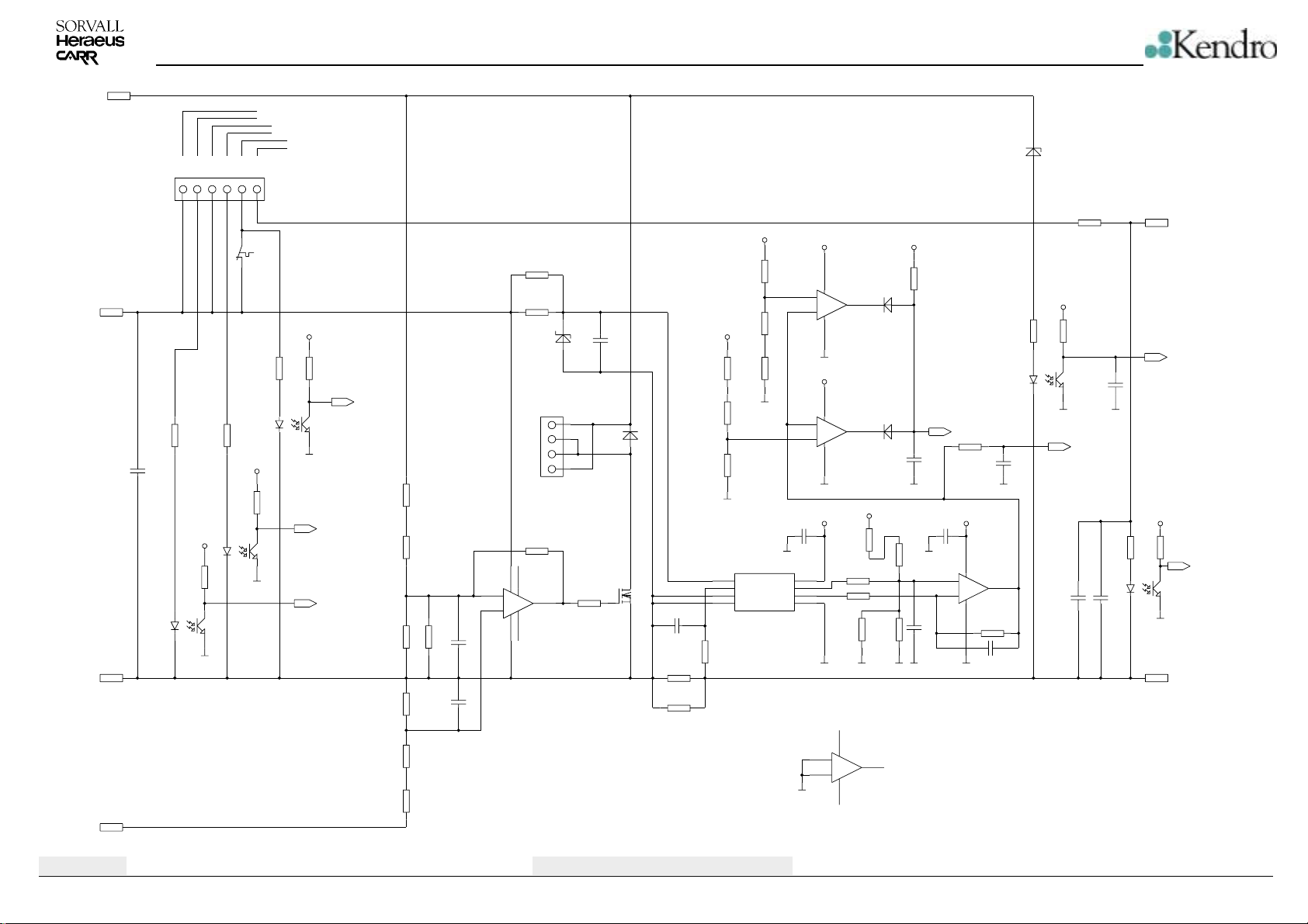
+20V
ZK2
+325V
0V
SCHEMATIC DIAGRAMS
Cooling Overpressure Switch
Motor Overtemperature Switch
Lid Switch
PPBBAA
X20
1
2
3
4
R75
10k
SMD
C46
100n
SMD
SFH6106-3
SMD
R80
10k
SMD
1
VCC
R144
1
U3
2
2
10k
SMD
3
4
GND
WAGO 256-606
5
6
VCC
GND
0.011 V/A
R23
47R
SMD
R87
1k2
SMD
R89
390R
SMD
R97
3k3
SMD
D18
1
VDD1
2
VIN+
3
VINGND14GND2
HCPL-7800
VCC
GND
0.24V
VCC
4
5
+
6
-
11
GND
VCC
4
3
+
2
-
11
GND
VCC
C53
100n
SMD
8
7
6
5
GND
Overcurrent Detector
10
GND
D19B
7
TLC2274C/SO
Acceleration Current
Limit +20A
D19A
1
TLC2274C/SO
Braking Current
Limit -20A
R81
10k
SMD 1%
R67
10k SMD 1%
R79 10k SMD 1%
R85
220k
SMD
4
+
9
TLC2274C/SO
11
VCC
3.76V
GND GND
VDD2
VOUT+
VOUT-
SMD 1%
D19C
8
VCC
R98
4k7
SMD
V39
LL4148
V40
LL4148
R84
18k
GND
R83
15k
SMD 1%
GNDGNDGND
C113
1n
SMD
C80
1n
SMD
/OVERCURRENT
R112
47k
SMD
VCC
C79
100n
SMD
4
12
+
13
-
11
GND
GND
D19D
14
TLC2274C/SO
R82
10k SMD 1%
C85 1n SMD
F3
THERMO SWITCH
P87 75 05 100 5A
mounted on heat sink of V33
VCC
R49
10k
SMD
VCC
R18
10k
SMD
3
4
GND
1
2
D23
SFH6106-3
SMD
R39
10k
SMD
ELECTRONIC_OVERTEMP
3
D17
SFH6106-3
SMD
4
GND
MOTOR_OVERTEMP
OVER_PRESSURE
SMD 1%
R70
470k
SMD 1%
R71
470k
SMD 1%
R68
R66
10k
SMD 1%
R72
470k
SMD 1%
R73
470k
SMD 1%
68k
SMD
C47
22p
SMD
C72
22p
SMD
R69
10k
R32
1k8 SMD
R50
1k8 SMD
2 Brake Resistors
D
R65
2M2
SMD
7
1
3
+
2
-
4
5
Dynamic Overvoltage Detector
Active, if the Motor
supplies Energy
V38
ZMM 5.1
XD1
1
2
3
4
Phoenix-Klemme
IGBT V50 with heat sink:
KUNZE KU 3-315/SO/VE
STW15NB50
D21
6
R74
TL081/SO
15R
SMD
V17
BA159
V50
C52
100n
SMD
C51
10n SMD
R88 0R022 4W
R52 0R022 4W
R96
470R
SMD
R86
3k9
SMD
R94
220R
SMD
R77
22k
SMD
C87
100n
SMD
V36
P6KE440A
1
2
C18
100u
SMD 25V +
R51
4R7
SMD
VCC
R78
10k
SMD
3
D22
SFH6106-3
SMD
4
GND
CURRENT
2V + 0.088 V/A
GND
R15
10k
SMD
C45
100n
SMD
Overvoltage Detector
Active, if Brake Resistor
is defect or Line Voltage
is much too high
C114
10n
SMD
VCC
1
2
GND
+20V_switched
/OVERVOLTAGE
R16
10k
SMD
3
U2
SFH6106-3
SMD
4
0V*
/LID_CLOSED
Edition: 04
04.07.02 AH
Main Board 184 - Protection Circuit
4-11
Multifuge 3S-R / 3L-R / Legend RT
Page 29
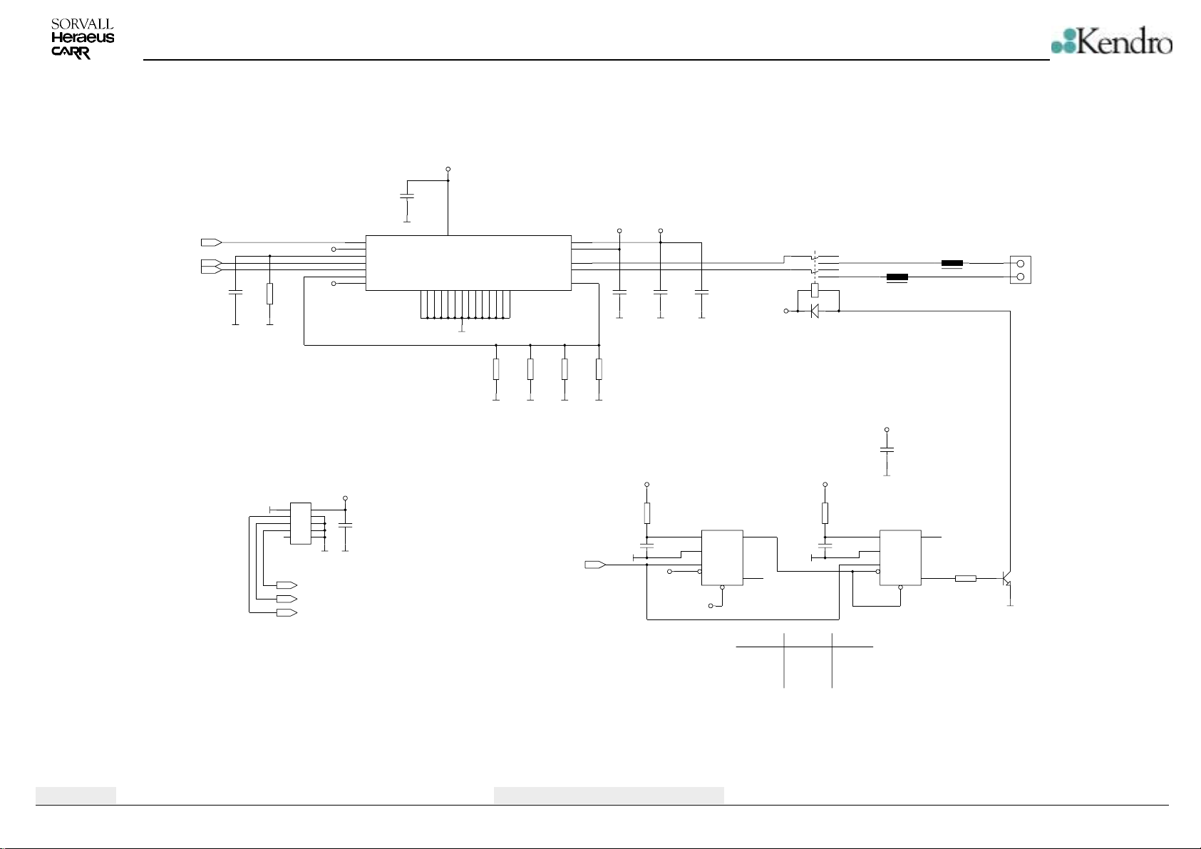
/LID_LOCK_BRAKE
LID_LOCK_DIRECTION
/LID_LOCK_ENABLE
SCHEMATIC DIAGRAMS
VCC
C95
100n
SMD
GND
2
/BRAKE
3
VCC
VCC
R108
22k
C37
SMD
1n
SMD
GNDGND
X14
2
1
GND
+
+
3
+
+
5
+
+
7
+
+
9
+
+
CON10AP
/LID_NEARLY_CLOSED
/LID_LOCK_CLOSED
/LID_LOCK_OPEN
4
6
8
10
GND
REF
4
RC
13
PHASE
14
/ENABLE
17
SENSE
27
MODE
D6 A3952SEB
VCC
C26
100n
SMD
GND
12
VCC
GND
GND
GND
GND
GND
GND
GND
GND
GND
GND
GND
GND
GND
GND
5
6
7
8
9
10
11
19
20
21
22
23
24
25
GND
R41
1R
SMD
LOAD_SUPPLY
LOAD_SUPPLY
OUT_B
OUT_A
EMITTERS
R42
1R
SMD
RPM_PULSE
15
1
28
16
18
R43
1R
SMD
GNDGNDGNDGND
+24V+24V
C90
C91
C20
100n
SMD
GNDGNDGND
T1 = 0.25sec
4538 SMD
2
1
4
5
VCC
+
470u
50V
D7A
6
RC
Q
CX
+T
-T
7
R
Q
3
Speed
0
<120RPM
>120RPM
100n
SMD
R44
1R
SMD
VCC VCC
R109
3M3
SMD
C92
100n
SMD
GND
VCC
RELAIS FINDER30.22 24V
10 11
+24V
V3 LL4148
R110
4M7
SMD
GND
Pin 6 Pin 9
Low
Pulse
High
K2
17
4
39
6
HF-DROSSEL
VCC
GND
T2 = 1.5 * T1
D7B
4538 SMD
C93
14
100n
15
SMD
12
11
High
High
Low
HF-DROSSEL
L2
C94
100n
SMD
RC
CX
+T
-T
R
13
L3
10
Q
R111
9
Q
10k
SMD
X13
1
2
WAGO 256-602
GND
Lid Lock DC Motor
V4
BC817-25
Edition: 04
04.07.02 AH
Main Board 184 - Lid Lock Control
4-12
Multifuge 3S-R / 3L-R / Legend RT
Page 30
SCHEMATIC DIAGRAMS
Edition: 04
04.07.02 AH
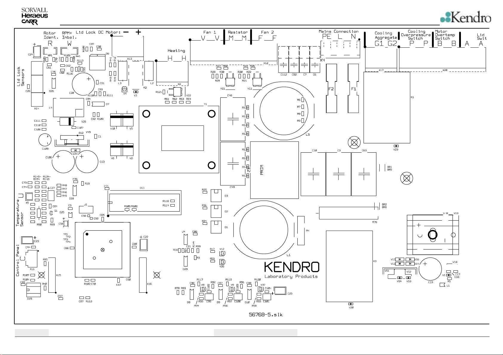
Component Plan Main board
4-13
Multifuge 3S-R / 3L-R / Legend RT
Page 31
SCHEMATIC DIAGRAMS
Edition: 04
04.07.02 AH
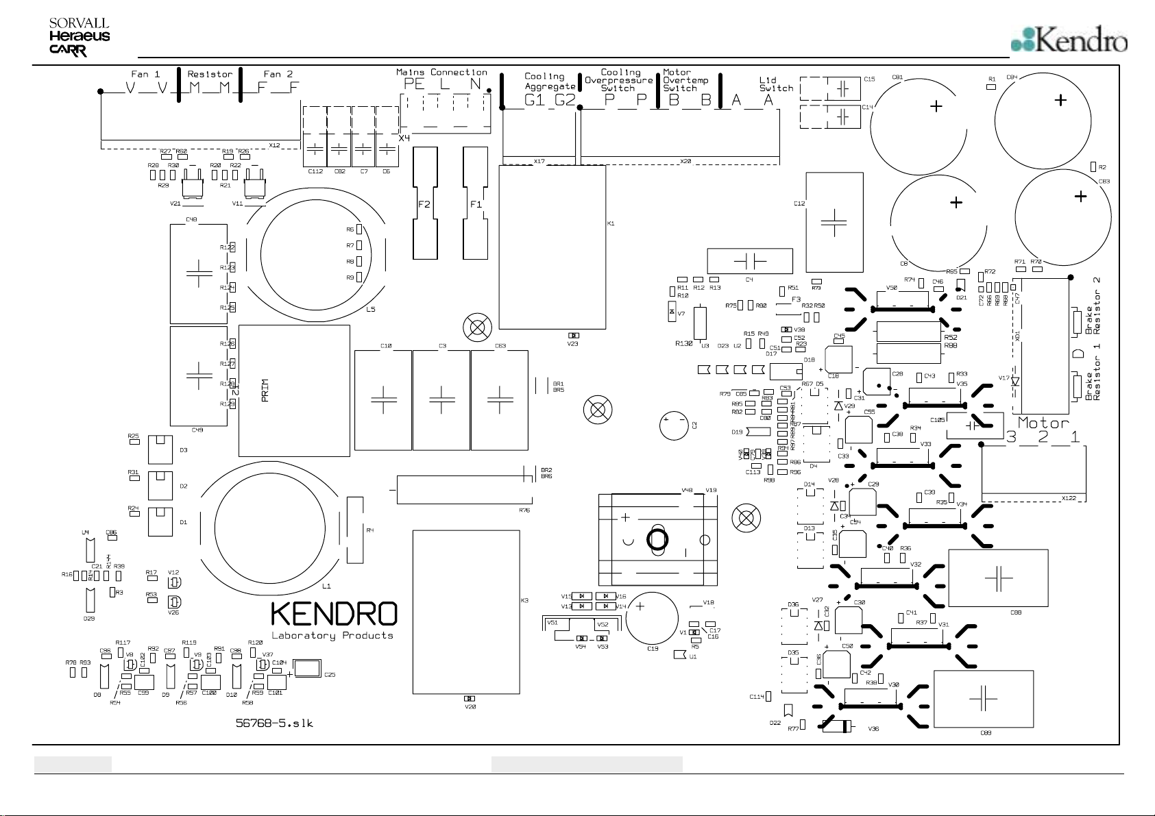
Component Plan Main board
4-14
Multifuge 3S-R / 3L-R / Legend RT
Page 32
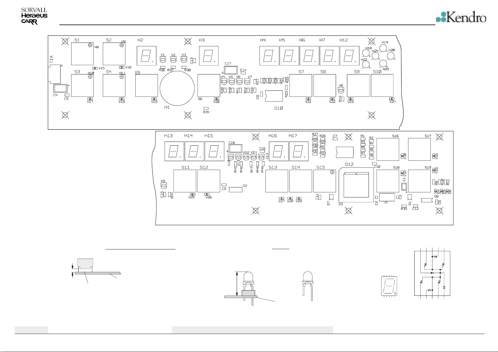
SCHEMATIC DIAGRAMS
Edition: 04
04.07.02 AH
Seven segment LED
1mm
distance plate of non conducting material
Seven segment LEDs
PCB
LED's
LED’s HLMP on sockets
with pins to top
8,5mm
Line verification of HLMP 3mm
KA
PCB
Component Plan Key and Indication board / Keypad version
4-15
876
Top view
TDSG 5150-M
10 9 8e67
54321
10 9
f
12
a
g
c
d
345
b
DP
Multifuge 3S-R / 3L-R / Legend RT
Page 33
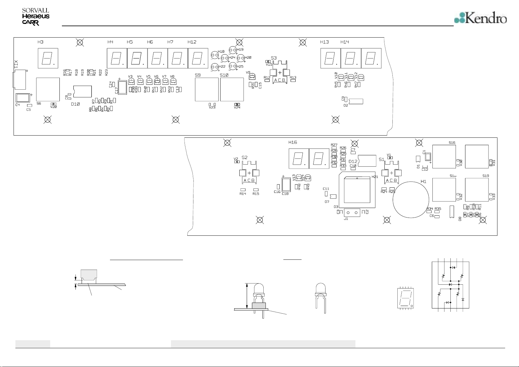
SCHEMATIC DIAGRAMS
Drehknopf - Version / Rotary switch version
Edition: 04
04.07.02 AH
Seven segment LED
1mm
distance plate of non conducting material
Seven segment LEDs
PCB
LED's
LED’s HLMP on sockets
with pins to top
8,5mm
Line verification of HLMP 3mm
KA
PCB
Component Plan Key and Indication board / Rotary switch version
4-16
876
Top view
TDSG 5150-M
10 9 8e67
54321
10 9
f
12
a
g
c
d
345
b
DP
Multifuge 3S-R / 3L-R / Legend RT
Page 34
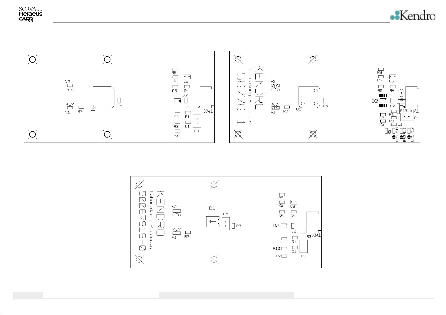
SCHEMATIC DIAGRAMS
Speed and Imbalance Detection Board P/N 70902651
Speed and Imbalance Detection Board P/N 20150214
Edition: 04
04.07.02 AH
Component Plan Speed and Imbalance detection board
4-17
Multifuge 3S-R / 3L-R / Legend RT
Page 35
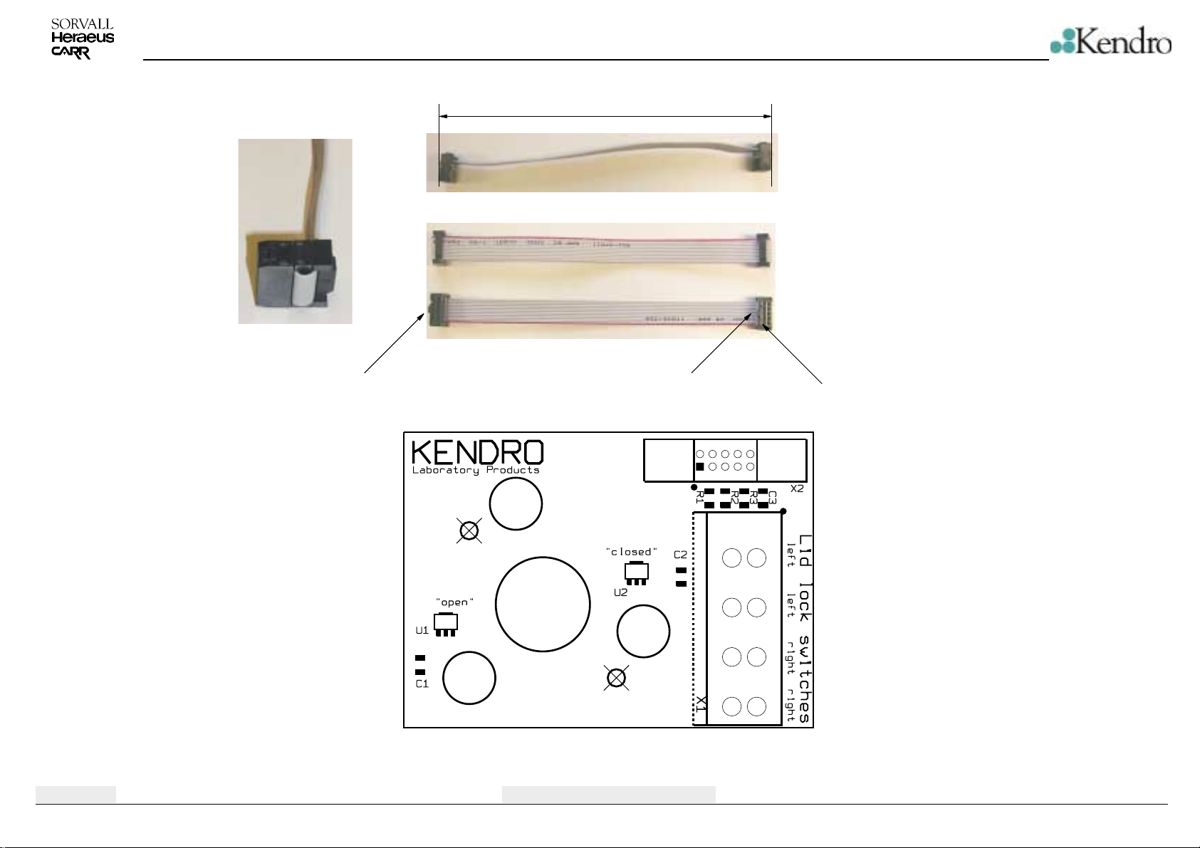
SCHEMATIC DIAGRAMS
180mm
Edition: 04
04.07.02 AH
Polarization NousePolarization Nouse
Component Plan Sensor board
4-18
Pin 1
Multifuge 3S-R / 3L-R / Legend RT
Page 36
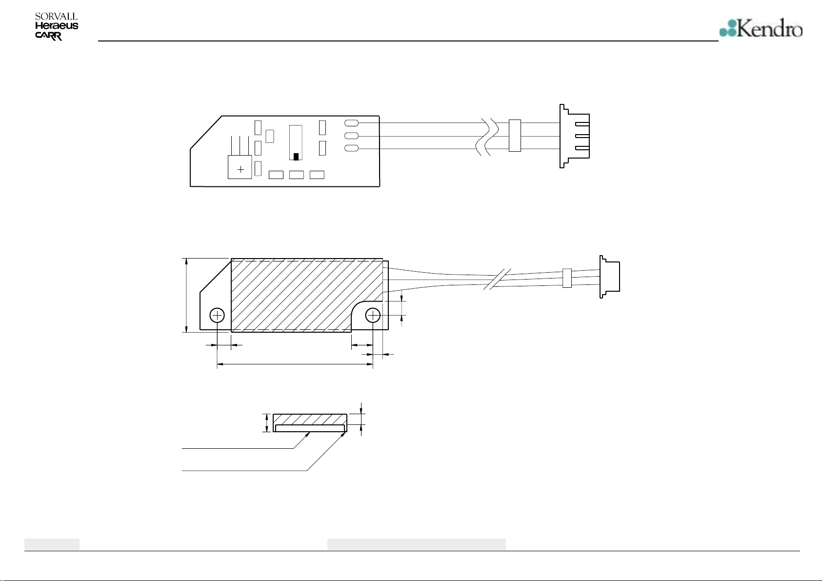
Old version of PCB
SCHEMATIC DIAGRAMS
max 16.45
R4A
C2A
R6A
D2A
R3A
R1A
R2A
R5A
C1A
D1A
R7A
Dimensions of cast PCB
min 3.11min 3.11
34.3
X3A
X2A
X1A
min 3.11
max 2.86
R
3
2
1
R
Wires are to guide lateral out of insulating compound
Edition: 04
04.07.02 AH
PCB
insulating compund
Insulating compound must not stand out below.
min 1.8
max 2.4
max.4.0
Component Plan Rotor detection board
4-19
Multifuge 3S-R / 3L-R / Legend RT
Page 37
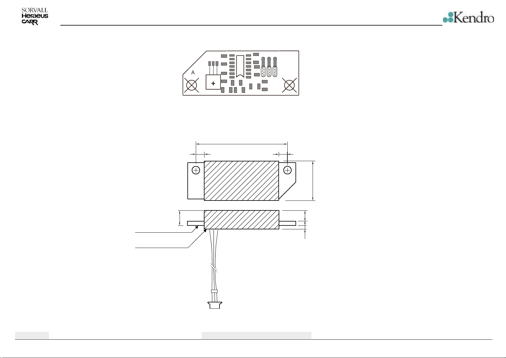
SCHEMATIC DIAGRAMS
X3A
X1A
X2A
PCB
R3A
R7A
34.3
34.3
D2A
R1A
R2A
R5A
C1A
R4A
R6A
D1A
C2A
Dimensions of cast PCB
34,3
min. 3,11 min. 3,11
min 3.11
min 3.11
max. 4
min 3.11
min 3.11
max 16.45
max 16.45
max. 16,45
min 1.8
min 1.8
max 2.4
max 2.4
min 0
min 0
max 1.4
max 1.4
Edition: 04
04.07.02 AH
insulating compund
Wires are to guide down side out of insulating compound
R
R
Component Plan Rotor detection board
4-20
Multifuge 3S-R / 3L-R / Legend RT
Page 38
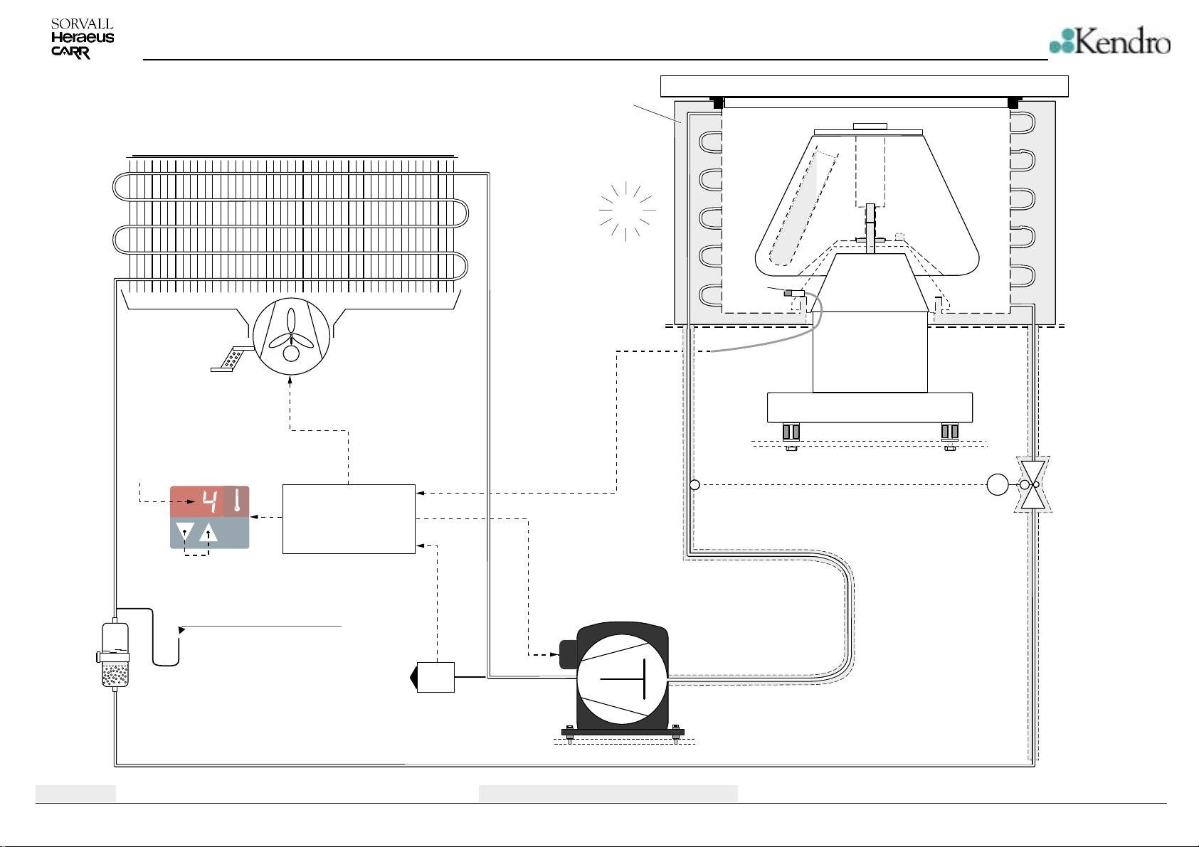
Condenser
Fan for Cooling Plant
SCHEMATIC DIAGRAMS
Evaporator Chamber
J
U
25°C
J
P
J
F
Edition: 04
04.07.02 AH
= f(n, - , rotor)
J
J
A
C
Liquid Collector + Dryer
J
S
U
J
S
0,510 kg (5bar)
R134A
CPU
Pressure
Switch
21bar
c.o.
>P
10 bar
c.i.
Compressor
Function Diagram of the Cooling Plant
4-21
Thermostatic Expansion Valve
TC
TLK 0.7, MOP -5°C
Multifuge 3S-R / 3L-R / Legend RT
Page 39

The index numbers stated in ( ) reappear within the spare part figures (block diagram, schematic
diagram of cooling plant) and the spare part lists. Due to cooled and non-cooled version are
described not all parts can be available.
5.1 Dismantling the Housing
5.1.1 Front Panel (800)
• Open the lid, switch off the unit and pull out the mains plug
• Remove screws underneath of the front-panel
• Move the panel right or at newer units, to the top and take it off
• Disconnect wiring from display board
5.1.2 Lid (620)
• Open the lid, switch off the unit and pull out the mains plug
• Knock carefully the joint bolts (511) for upper attaching of gas lid stays (515) out of joint blocks
(610) with its three notches ahead by use of a hammer and pin punches (but press the bolts in
with non notches ahead by use of pliers)
• Push an adequate screw driver into one bolt’s place to keep the gas lid stay in position to avoid
lid’s slamming
• Remove the 6 screws for lid’s attaching on both hinges
• Take the screw driver out of joint blocks to separate lid from gas stay and remove the lid from
casing
• When reassembling the lid take care that both bolt keepers (605) engage the lock entries
concentric and stand out of the screw-in hollow exactly for 36mm
5.1.3 Casing (500)
• Remove the front panel (800) - see 5.1.1
• Remove the lid (620) - see 5.1.2
• Remove main board – see 5.2.2
• Remove the 4 remaining screws on both sides
• Disconnect the grounding line and remove the casing with lid (500) and bolt holes sealing in
vertical position from armoured chamber and frame
• Reassemble the casing analogously in reverse order and take care of the correct lid sealing seat
(320)
5.1.4. Automatic Lid Locking System (475)
• Dismantle the front panel (800) - see 5.1.1
• Dismantle main board – see 5.2.2
• Disconnect plug X13 turn the motor with help of an auxiliary voltage DC 12V into a position that
you can remove the 3 screws
• Remove lower nut of the latch holder bar
• Remove latch holder bar
• Disconnect wiring of micro switches and flat cable on PCB attached to gear motor
• Remove 4 set screws (2 x 2) in positioner
• Reinstall the latch and gear motor in reverse order
• Make sure that the center micro-switch is proper adjusted
• Move latch to the maximum top position, loose the two screws of micro switch move it until it
“clicks”
• Check by driving the latch up and down with help of auxiliary voltage
Edition: 03 Servicing Schedule
13.0301/he/AH Page: 5 - 1
Legend RT
Multifuge 3S-R/3L-R
Page 40

5.1.5 Gas Lid Stays (515)
• Open the lid, switch off the unit, pull out the mains plug and remove the rotor
• Remove the lid - see 5.1.3
• Remove the casing - see 5.1.4
• Remove the attaching screws for the lower joint blocks
• Knock carefully the joint bolts (511) for lower attaching of gas lid stays (515) out of joint blocks
(610) with its three notches ahead by use of hammer and pin punches (but press the bolt in
with non notches ahead by use of pliers)
• Replace both worn out gas lid stays and reinstall the new gas lid stays analogously in reverse
order and remount the unit completely.
5.2 Replacement of Electrical Components
5.2.1 NV-RAM, E-PROM on the Main Board
• Notice old displayed identification and version numbers of E-PROM and NV-RAM when powering
on (2./3. No. in sequence)
• See wiring diagram and remove the front panel (800) - see 5.1.1
• Remove main board - see 5.2.2
• ATTENTION - CMOS components! Discharge your body before handling! Pull CPU
and/or NV-RAM carefully out of socket using chip removal tool
• Reinsert the new IC’s correctly
• Put the front panel back in position, switch power ON, check the displayed identification and
version numbers of the new ICs and refit the front panel
5.2.2 Main Board Replacement (700)
• dismantle the front panel (800) - see 5.1.1
• Remove the screws which fasten the board and place it in front of the unit
• Remove all wires from the terminals by pressing the lever. Unplug XC, XR, XU*, XW. Only the
main cable is fastened in a screwed terminal.
• touch a grounded receptacle to discharge your body before touching the sensitive CMOS
components! Take the new CPU and/or NV-RAM out of box (or re-use the old ones when in
perfect condition) and insert them into sockets of the new main board (if necessary, remove the
placed but non-programmed NV-RAM before)
• remount the new main board with all nuts and washers
• Do not mix up disconnected cables during re-connection!
• Reassemble the device in reverse order and perform a test run, making sure the drive turns in
the right direction (see imprinted arrow on rim of rotor chamber)!
5.2.3 Key and Display Board (810)
• Remove the front panel (800) - see 5.1.1
• Remove the attaching screws and take out the indication board
• Unplug the connecting line to main board and transfer to new board
• Reassemble the indication board analogously in reverse order, check controller identification and
refit the front panel
5.2.4 Rotor Indication Board (137)
• The sensor board is placed on the motor and fixed at the pins with Loctite. It can be easily
removed by pulling carefully.
Edition: 03 Servicing Schedule
13.0301/he/AH Page: 5 - 2
Legend RT
Multifuge 3S-R/3L-R
Page 41

5.2.5 Speed Detection Board (140)
• Remove the drive with mounting plate - see 5.3.2 and deposit upside down
• Remove the screws and lock washers and take out the board
• Unplug the connecting line to main board and transfer to new detection board
• Remount the speed detection board (plug position: left to back), reassemble the unit analogously
in reverse order and perform a test run
5.2.6 Fans
• Condenser fan, right side: (235):
• Remove front panel see 5.1.1
• Remove main board see 5.2.2
• Take fan apart
5.2.7 Brake Resistor (255/256)
• Remove front panel - see 5.1.1
• Remove the main board – see 5.2.2
• Remove housing only in case of resistor change
• Check the resistance of both brake resistors and replace defective resistor(s)
• Check thermos switch on R 2
• Check the cleanliness of air louvers and clean them if necessary, pay attention to good heat
transmission
• Reassemble the device analogously in reverse order. Perform some short test runs with max
brake curve.
5.3 Replacement of Drive Components
5.3.1 Drive Motor (135)
• Remove Motor cover with sensor cover
• Remove the front panel and main board - see 5.1.1 and 5.2.2
• Disconnect the leads for motor X122 (U,V,W), over temperature switch X20, unplug the
grounding wire PE from casing’s receptacle
• Remove ferroxcube from the motor wires in front safety chamber and tie a string for easier pulling
afterwards
• Remove rotor recognition board and put it on side
• Remove temperature sensor (if available)
• Unscrew motor take it off
• Remove speed detection board and reinstall it at the new motor
5.3.2 Motor rubber Mounts (104)
• Remove motor – see 5.3.1
• Place unit on 4 blocks of wood (10 to 15 cm)
• Remove 10 screw underneath base plate
• Base plate will not come off
• Turn the base plate 1,5 cm until the holder screws allow to remove the plate
• Inspect the rubber mounts and if necessary replace them
• All 6 rubber mounts must only be exchanged completely!
• Take care that the safety screws will not be damaged or loosen (non-cooled version only)
Edition: 03 Servicing Schedule
13.0301/he/AH Page: 5 - 3
Legend RT
Multifuge 3S-R/3L-R
Page 42

5.3.3 Adjustment of the micro switch (center of Latch system)
• Remove front-panel and main board see 5.1.1 and 5.2.2
• Move the latch sleigh to the maximum top by help of auxiliary voltage
• Loosen the two screws of the micro-switch and move it in a position that a clear click can be
heard + 0,5 to 1mm – check with multimeter for zero ohm
• Connect motor to power supply and make sure that the switch is functioning well
• Secure the bolts with paint
5.4 Replacement of Parts of the Cooling Plant*
First of all is to figure out that high ambient temperatures (ϑU >35°C), insufficient heat transfer (e.g.
polluted condenser, de-heater, air gaps) or electrical errors (like defective fans, sensor or main board,
starting relay or capacitor) can be excluded from the cooling problem (see function diagram of cooling
plant 4-10: pressure / temperature ranges are valid for continuous cooling at max. speed, ϑU=25°C)!
Procedure for replacing defective components of the cooling cycle:
• Dismantle the casing -see 5.1.and mount pierce valves onto the service lines
• When gauging too little static pressure perform a leakage test (N2 max. 25bars)
• Discharge the refrigerant with suction device into recycling bottle
• In case of compressor (200) fault, let the oil run out into a bowl to recycle it
• Unsolder defective component(s) and replace the dryer/collector assy (235), too
• Let a little amount of dry nitrogen gas stream through the tubes when soldering to avoid scaling
on the tube’s inner surface
• Do the evacuation and refill the system with the exact amount of liquid refrigerant on the pressure
side via a new external dryer (check amount with a balance or filling cylinder, re-solder the
service lines tight after finishing work)
• Reassemble the device and perform a cooling power test run.
Charging information 120 V version:
Refrigerant: R 134a
Amount: 510 grams (17,8 oz)
Operating pressure with rotor 75006445 and round buckets 75006441, n = 3750 rpm
Ambient: 23°C (73°F)
Temperature selection: minimum
Time: 3 hours
Suction: 1,9 +/-0,1 bars (-12 °C) 27,15 psi
Discharge: 7,5 bars (30 °C) 107,2 psi
Edition: 03 Servicing Schedule
13.0301/he/AH Page: 5 - 4
Legend RT
Multifuge 3S-R/3L-R
Page 43
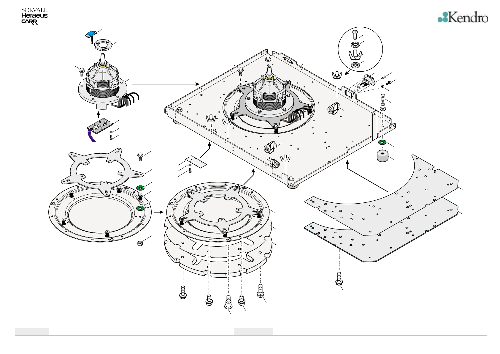
BREAK DOWN DRAWINGS
138
137
136
140
142
141
135
231
130
105
104
105
125
126
127
231
170
171
100
171
127
161
160
161
150
151
152
153
121
105
120
110
Edition: 04
05.07.02 AH
106
103
101
Bottom Plate
6-1
109
102
107/112
108
111
231
Multifuge 3S-R / 3L-R / Legend RT
Page 44
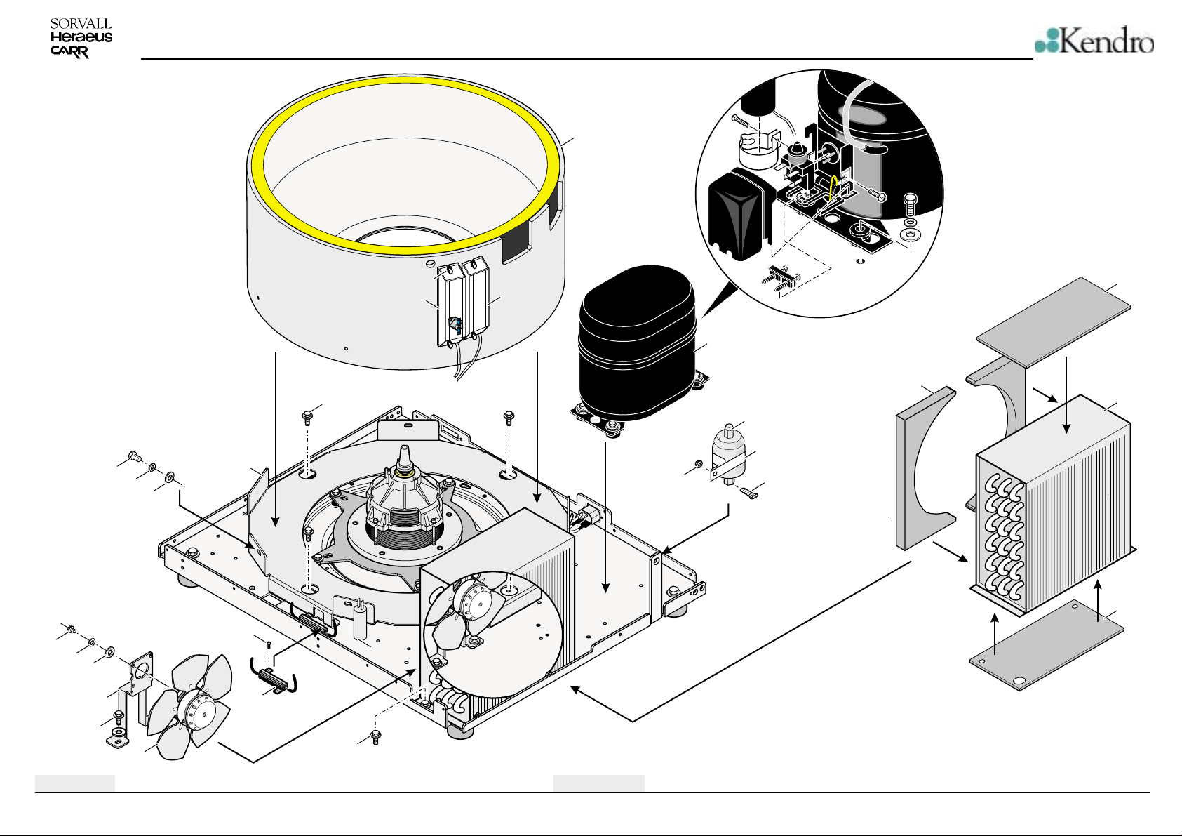
BREAK DOWN DRAWINGS
250
237
126
236
251
682
681
240
141
231
265
257
256
255
106
222
200
223
220
270
271
272
221
230
231
Edition: 04
05.07.02 AH
235
260
224
Bottom Plate
6-2
Multifuge 3S-R / 3L-R / Legend RT
Page 45
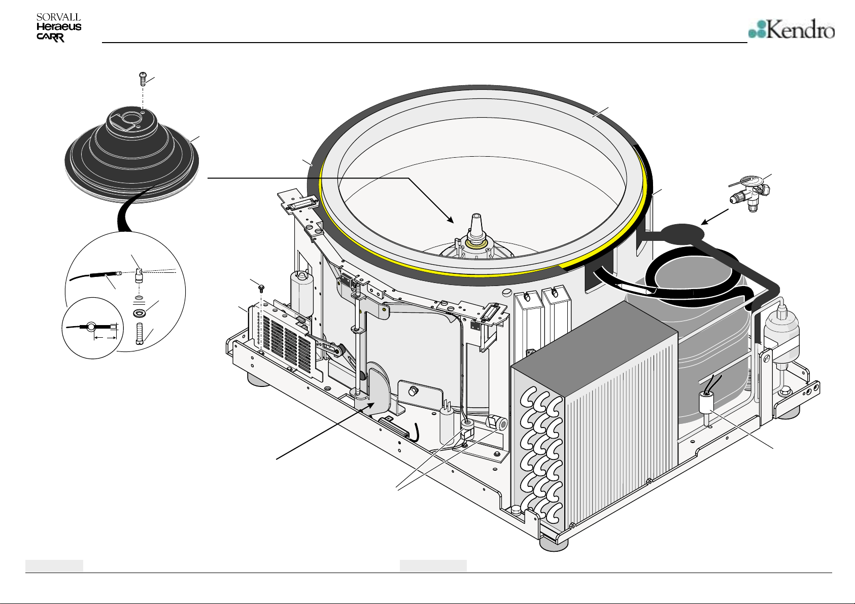
335
BREAK DOWN DRAWINGS
326
310
325
320
305
315
330
257
336
340
337
Edition: 04
05.07.02 AH
20mm
Lid lock see page 6-4
170
Bottom Plate
6-3
300
Multifuge 3S-R / 3L-R / Legend RT
Page 46
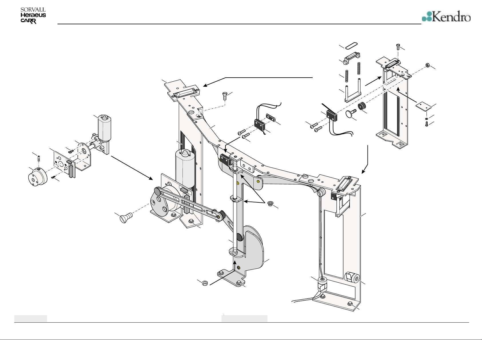
BREAK DOWN DRAWINGS
Parts for left and right lid lock are the same
416
415
410
406
141
405
400
417
420
432
465
212
461
470
471
476
461
460
454
452
451
450
441
440
425
453
442
430
126
431
Edition: 04
05.07.02 AH
481
231
480
481
231
Lid Lock System
6-4
475
170
170
231
Multifuge 3S-R / 3L-R / Legend RT
Page 47
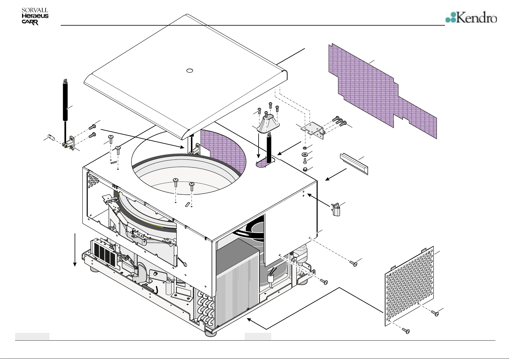
Parts for the lid see page 6-6
515
511511
BREAK DOWN DRAWINGS
521
520
535
505
511
516
510
511
682
681
680
685
525
530
500
540
511
511
Edition: 04
05.07.02 AH
Housing
6-5
Multifuge 3S-R / 3L-R / Legend RT
Page 48
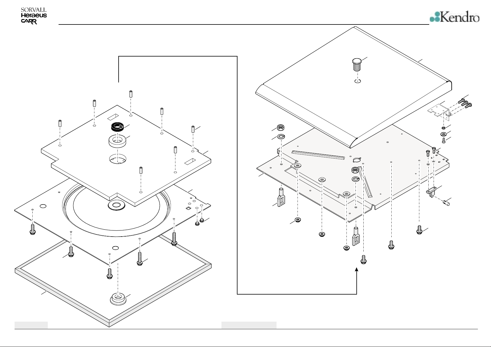
BREAK DOWN DRAWINGS
635
640
645
631
630
685
600
607
606
605
621
670
620
511
535
682
681
680
212
510
511
257
650
Edition: 04
05.07.02 AH
511
671
660
Lid
6-6
Multifuge 3S-R / 3L-R / Legend RT
Page 49
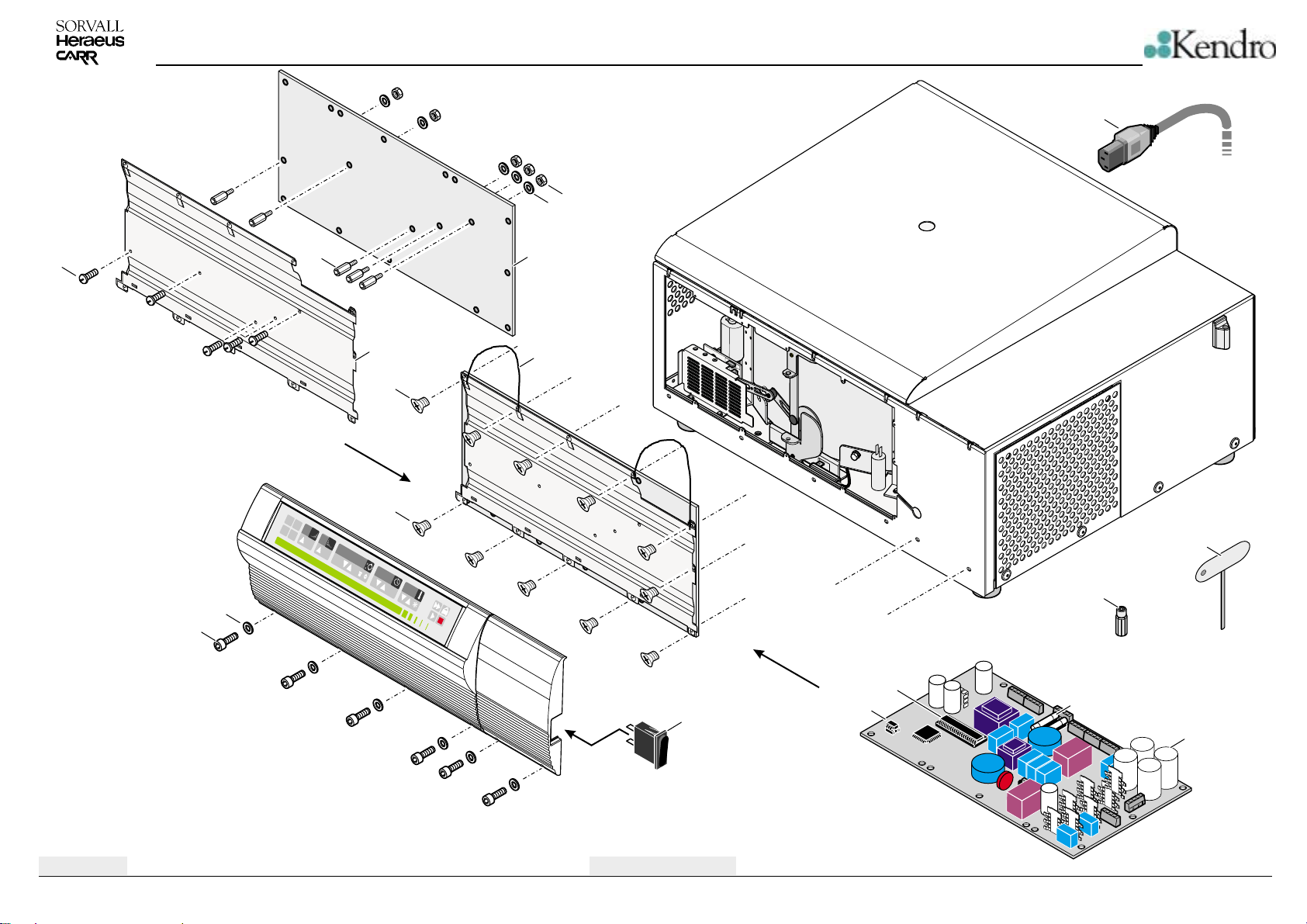
BREAK DOWN DRAWINGS
713
712
730
714
720
721
1
2
3
4
SORVALL
711
0
®
LEGEND
0
RT
710
715
715
rpm
x
x
g
g
700
770
725
701
735
740
702
703
700
Edition: 04
05.07.02 AH
Parts for front panel see page 6-8
Front Panel
6-7
Multifuge 3S-R / 3L-R / Legend RT
Page 50
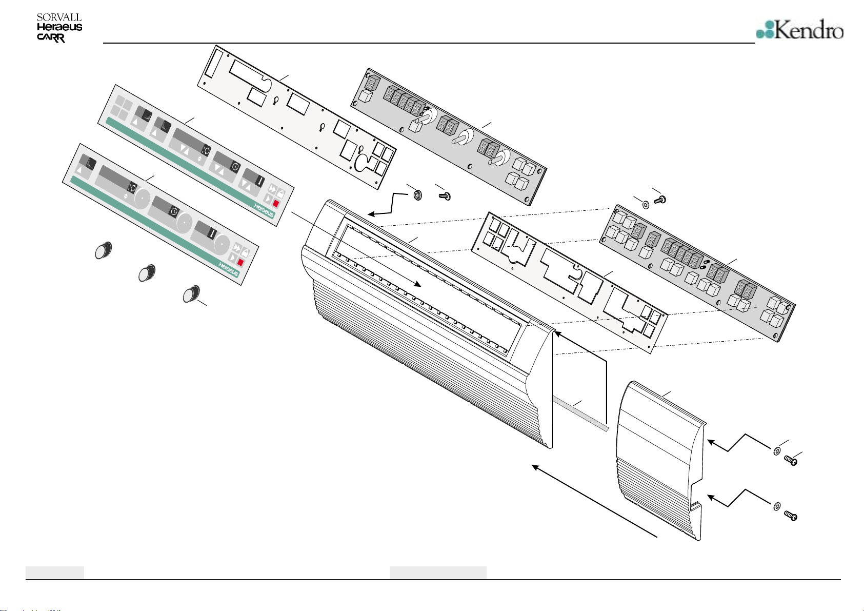
0
MULTIGUGE 3
1
2
3
4
MULTIGUGE 3
L-R
BREAK DOWN DRAWINGS
820
0
L-R
825
min
-1-1
xg
x
g
825
0
min
-1-1
xg
x
g
846
845
810
521
811
800
810
820
826
Edition: 04
05.07.02 AH
Front Panel
6-8
840
830
236
831
Multifuge 3S-R / 3L-R / Legend RT
Page 51
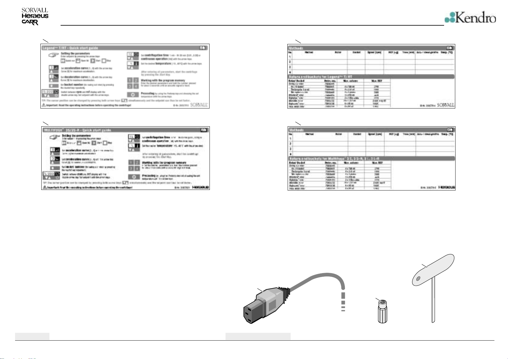
BREAK DOWN DRAWINGS
900
901
910
911
Edition: 04
05.07.02 AH
730
Accessories
6-9
735
740
Multifuge 3S-R / 3L-R / Legend RT
Page 52

Spare-Part-List
Index
to Serial-No.
-
75004374
01
Kendro Laboratory Products
Plant Osterode
MULTIFUGE 3L-R 120V/60HZ
from Serial-No.
00100 70056704 Base
00101 20460089 SCREW M5X5
00102 20057535 Motorchassis
00103 20510292 SCREW
00104 20022874 ANTIVIBRATION MOUNT
00105 10104080 WASHER (SAND)
00106 20420167 NUT
00107 20057828 Noise reducer
00108 20057826 Weight
00109 20510356 Bolt
00110 20057827 Noise reducer
00111 70060304 Metallsheet
00112 20057941 Insulation
00120 20300084 FOOT
00121 20510247 Screw M8x12
00125 70057541 Chassis cover
00126 20480244 LOCK WASHER
00127 20460092 ALLEN SCREW M4 X 6
00130 70057534 Motorchassis
00135 20210390 MOTOR 125/45 3PH
00136 20056798 Insulation
00137 20150180 ROTOR RECOGNITION
00138 20510350 Bolt
00140 20150214 Speed and imbalance recognition
00141 20460097 Z-SCREW M3 X 8
00142 20480242 SECURING WASHER
00150 20180608 RECEPTACLE
00151 20440023 SCREW M3 X 8
00152 20460090 SCREW M4X12
00153 20420076 HEXAGONAL NUT M4
00160 20180138 CONNECTOR
00161 20480108 FAN WASHER A 4,3
00170 20170329 Ferroxcube ring
00171 20170330 FERROXCUBE
00200 20240607 Compressor SC 12 GX 115V/60Hz
00220 20056700 CONDENSOR
00221 20057488 Insulation
00222 20057487 Insulation
40031227
Partno.
Text
Donnerstag, 22. November 2001
Seite 1
Page 53

Spare-Part-List
Index
to Serial-No.
-
75004374
01
Kendro Laboratory Products
Plant Osterode
MULTIFUGE 3L-R 120V/60HZ
from Serial-No.
00223 20056735 COVER
00224 20510354 Screw
00230 70056716 Bracket Fan00231 20510292 SCREW
00235 20210397 MOTOR FAN 115 V
00236 20480224 WASHER A 4,3
00237 20430207 SCREW M 4 X 10
00240 70056705 Evaporatorchassis
00250 70904335 Evaporator complete
00251 20430212 SCREW M 5 X 16
00255 20160733 RESISTOR 120 OHM
00256 20160734 RESISTOR 120 OHM
00257 20510352 Screw
00260 70904550 Resistor 100 Ohm F. Multi 3 R 120V
00265 20160737 CAPACITOR 4UF/400V
00270 20240577 FILTERDRYER
00271 20220598 Clip
00272 20440221 SCREW M 6 X 16
00300 20240592 HIGH PRESSURE CONTROLL SWITC
00305 20240608 Injection valve
00310 20056748 SEAL
00315 20290556 Insulation
00320 20290673 Insulation Armaflex
00325 20056761 MOTORCOVER
00326 20460103 SCREW M 3 X 12
00330 20055509 SUPPORT
00335 20140602 Sensor Temp. PT 100
00336 20250074 WASHER
00337 20470253 SCREW, PLASTIC
00340 70057552 Metall sheet
00400 20210391 MOTOR W GEAR
00405 20056715 Holder
00406 20460163 Screw
00410 20150186 PCB SENSOR
00415 70904339 COUPLING
00416 20510288 Set screw
00417 20440285 SCREW
00420 70056790 Sheet, left
40031227
Partno.
Text
Donnerstag, 22. November 2001
Seite 2
Page 54

Spare-Part-List
Index
to Serial-No.
-
75004374
01
Kendro Laboratory Products
Plant Osterode
MULTIFUGE 3L-R 120V/60HZ
from Serial-No.
00425 70056789 Sheet, right
00430 20056737 Slideplate
00431 20460092 ALLEN SCREW M4 X 6
00432 20220586 INSULATION
00440 20056738 Roller
00441 20056739 Bolt 4
00442 20420107 NUT M 6 LEFT
00450 20056792 HOLDER LATCH PROTECTION
00451 20350242 Spring
00452 20056791 LATCH PROTECTION
00453 20460202 Screw Ejot
00454 20057932 Insulation
00460 20180677 SWITCH
00461 20460157 Bolt M 2,3
00465 70056718 Bracket, Latch00470 20180654 SWITCH
00471 20057257 Holder sheet
00475 70904336 LATCH ASSY
00476 20350241 Clip
00480 20056707 Bar
00481 20420070 NUT M 6
00500 70056726 Housing
00505 20057830 Grill
00510 20056650 HOLDER
00511 20510285 SCREW M5 X 12
00515 20310439 GAS LID STAY
00516 20490287 PIN
00520 20056766 SEAL
00521 20510294 SCREW M3 X 10
00525 20310442 Puller
00530 20057553 Holder, Tool00535 20056736 HINGE
00540 20056795 Panel, right
00600 70056741 Insert
00605 20057217 HOOK
00606 20480236 SECURING WASHER
00607 20420121 NUT M 10 X 1,25
00620 70904183 Cover, door
40031227
Partno.
Text
Donnerstag, 22. November 2001
Seite 3
Page 55

Spare-Part-List
Index
to Serial-No.
-
75004374
01
Kendro Laboratory Products
Plant Osterode
MULTIFUGE 3L-R 120V/60HZ
from Serial-No.
00621 20420201 Nut
00630 20056731 Insulation, door
00631 20056762 Spacer
00635 20057563 Spacer
00640 20056734 Insulation small
00645 20056728 INSERT
00650 20057833 Seal
00660 20510360 Screw M5
00670 20056732 Window
00671 20056625 WINDOW, LOWER PART
00680 20510021 SCREW M 5 X 12
00681 20480200 WASHER
00682 20480167 FAN WASHER A 5,1
00685 20310504 Cover
00700 20150184 MAINBOARD 120V
00701 70904557 NV RAM
00702 70000528 PROCESSOR MAIN Legend 0528V07
00703 20230172 FUSE 15 A
00710 70060305 Cover
00711 20500200 Spacer
00712 20480300 Washer M4
00713 20420200 Nut M4
00714 20470263 Screw
00715 20440284 SCREW M 4 X 8
00720 20510293 Screw
00721 20480130 WASHER 4,3
00725 20180671 SWITCH W OVERLOADPROT. 16 A
00730 20190300 Cordset NEMA 5-15P 15A/125V 3x14A
00735 20360073 SCREW DRIVER
00740 20904430 COLLET CHUCK
00770 20310508 String w washer
00800 70060312 Frontpanel
00810 20150191 DISPLAY PCB
00811 20480124 WASHER
00820 20057551 Frontplate
00825 20057905 Overlay Multifuge 3L-R
00826 20310443 Knob f. Quickcontrolpanal Multifuge
00830 20056759 FRONTPANEL SIDE
40031227
Partno.
Text
Donnerstag, 22. November 2001
Seite 4
Page 56

Spare-Part-List
Index
to Serial-No.
-
75004374
01
Kendro Laboratory Products
Plant Osterode
MULTIFUGE 3L-R 120V/60HZ
from Serial-No.
00831 20460164 Screw
00840 20290664 seal
00845 20057560 Spacer
00846 20460161 SCREW
00900 20057916 Operating instruction
00901 20057821 Short Instruction for Multifuge 3S engl.
00910 20057914 Instruction
00911 20057915
40031227
Partno.
Text
Donnerstag, 22. November 2001
Seite 5
Page 57

Spare-Part-List
Index
to Serial-No.
-
75004375
01
Kendro Laboratory Products
Plant Osterode
MULTIFUGE 3 S-R, 120V/60HZ
from Serial-No.
00100 70056704 Base
00101 20460089 SCREW M5X5
00102 20057535 Motorchassis
00103 20510292 SCREW
00104 20022874 ANTIVIBRATION MOUNT
00105 10104080 WASHER (SAND)
00106 20420167 NUT
00107 20057828 Noise reducer
00108 20057826 Weight
00109 20510356 Bolt
00110 20057827 Noise reducer
00111 70060304 Metallsheet
00112 20057941 Insulation
00120 20300084 FOOT
00121 20510247 Screw M8x12
00125 70057541 Chassis cover
00126 20480244 LOCK WASHER
00127 20460092 ALLEN SCREW M4 X 6
00130 70057534 Motorchassis
00135 20210390 MOTOR 125/45 3PH
00136 20056798 Insulation
00137 20150180 ROTOR RECOGNITION
00138 20510350 Bolt
00140 20150214 Speed and imbalance recognition
00141 20460097 Z-SCREW M3 X 8
00142 20480242 SECURING WASHER
00150 20180608 RECEPTACLE
00151 20440023 SCREW M3 X 8
00152 20460090 SCREW M4X12
00153 20420076 HEXAGONAL NUT M4
00160 20180138 CONNECTOR
00161 20480108 FAN WASHER A 4,3
00170 20170329 Ferroxcube ring
00171 20170330 FERROXCUBE
00200 20240607 Compressor SC 12 GX 115V/60Hz
00220 20056700 CONDENSOR
00221 20057488 Insulation
00222 20057487 Insulation
40031227
Partno.
Text
Donnerstag, 22. November 2001
Seite 1
Page 58

Spare-Part-List
Index
to Serial-No.
-
75004375
01
Kendro Laboratory Products
Plant Osterode
MULTIFUGE 3 S-R, 120V/60HZ
from Serial-No.
00223 20056735 COVER
00224 20510354 Screw
00230 70056716 Bracket Fan00231 20510292 SCREW
00235 20210397 MOTOR FAN 115 V
00236 20480224 WASHER A 4,3
00237 20430207 SCREW M 4 X 10
00240 70056705 Evaporatorchassis
00250 70904335 Evaporator complete
00251 20430212 SCREW M 5 X 16
00255 20160733 RESISTOR 120 OHM
00256 20160734 RESISTOR 120 OHM
00257 20510352 Screw
00260 70904550 Resistor 100 Ohm F. Multi 3 R 120V
00265 20160737 CAPACITOR 4UF/400V
00270 20240577 FILTERDRYER
00271 20220598 Clip
00272 20440221 SCREW M 6 X 16
00300 20240592 HIGH PRESSURE CONTROLL SWITC
00305 20240608 Injection valve
00310 20056748 SEAL
00315 20290556 Insulation
00320 20290673 Insulation Armaflex
00325 20056761 MOTORCOVER
00326 20460103 SCREW M 3 X 12
00330 20055509 SUPPORT
00335 20140602 Sensor Temp. PT 100
00336 20250074 WASHER
00337 20470253 SCREW, PLASTIC
00340 70057552 Metall sheet
00400 20210391 MOTOR W GEAR
00405 20056715 Holder
00406 20460163 Screw
00410 20150186 PCB SENSOR
00415 70904339 COUPLING
00416 20510288 Set screw
00417 20440285 SCREW
00420 70056790 Sheet, left
40031227
Partno.
Text
Donnerstag, 22. November 2001
Seite 2
Page 59

Spare-Part-List
Index
to Serial-No.
-
75004375
01
Kendro Laboratory Products
Plant Osterode
MULTIFUGE 3 S-R, 120V/60HZ
from Serial-No.
00425 70056789 Sheet, right
00430 20056737 Slideplate
00431 20460092 ALLEN SCREW M4 X 6
00432 20220586 INSULATION
00440 20056738 Roller
00441 20056739 Bolt 4
00442 20420107 NUT M 6 LEFT
00450 20056792 HOLDER LATCH PROTECTION
00451 20350242 Spring
00452 20056791 LATCH PROTECTION
00453 20460202 Screw Ejot
00454 20057932 Insulation
00460 20180677 SWITCH
00461 20460157 Bolt M 2,3
00465 70056718 Bracket, Latch00470 20180654 SWITCH
00471 20057257 Holder sheet
00475 70904336 LATCH ASSY
00476 20350241 Clip
00480 20056707 Bar
00481 20420070 NUT M 6
00500 70056726 Housing
00505 20057830 Grill
00510 20056650 HOLDER
00511 20510285 SCREW M5 X 12
00515 20310439 GAS LID STAY
00516 20490287 PIN
00520 20056766 SEAL
00521 20510294 SCREW M3 X 10
00525 20310442 Puller
00530 20057553 Holder, Tool00535 20056736 HINGE
00540 20056795 Panel, right
00600 70056741 Insert
00605 20057217 HOOK
00606 20480236 SECURING WASHER
00607 20420121 NUT M 10 X 1,25
00620 70904183 Cover, door
40031227
Partno.
Text
Donnerstag, 22. November 2001
Seite 3
Page 60

Spare-Part-List
Index
to Serial-No.
-
75004375
01
Kendro Laboratory Products
Plant Osterode
MULTIFUGE 3 S-R, 120V/60HZ
from Serial-No.
00621 20420201 Nut
00630 20056731 Insulation, door
00631 20056762 Spacer
00635 20057563 Spacer
00640 20056734 Insulation small
00645 20056728 INSERT
00650 20057833 Seal
00660 20510360 Screw M5
00670 20056732 Window
00671 20056625 WINDOW, LOWER PART
00680 20510021 SCREW M 5 X 12
00681 20480200 WASHER
00682 20480167 FAN WASHER A 5,1
00685 20310504 Cover
00700 20150184 MAINBOARD 120V
00701 70904552 NV-RAM PRV MULTI 3S-R / 120V 045
00702 70000528 PROCESSOR MAIN Legend 0528V07
00703 20230172 FUSE 15 A
00710 70060305 Cover
00711 20500200 Spacer
00712 20480300 Washer M4
00713 20420200 Nut M4
00714 20470263 Screw
00715 20440284 SCREW M 4 X 8
00720 20510293 Screw
00721 20480130 WASHER 4,3
00725 20180671 SWITCH W OVERLOADPROT. 16 A
00730 20190300 Cordset NEMA 5-15P 15A/125V 3x14A
00735 20360073 SCREW DRIVER
00740 20904430 COLLET CHUCK
00770 20310508 String w washer
00800 70060312 Frontpanel
00810 20150190 DISPLAY PCB
00811 20480124 WASHER
00820 20057550 FRONT
00825 20057904 Overlay
00830 20056759 FRONTPANEL SIDE
00831 20460164 Screw
40031227
Partno.
Text
Donnerstag, 22. November 2001
Seite 4
Page 61

Spare-Part-List
Index
to Serial-No.
-
75004375
01
Kendro Laboratory Products
Plant Osterode
MULTIFUGE 3 S-R, 120V/60HZ
from Serial-No.
00840 20290664 seal
00845 20057560 Spacer
00846 20460161 SCREW
00900 20057916 Operating instruction
00901 20057821 Short Instruction for Multifuge 3S engl.
00910 20057914 Instruction
00911 20057915
40031227
Partno.
Text
Donnerstag, 22. November 2001
Seite 5
Page 62

Spare-Part-List
Index
-
75004376
01
Kendro Laboratory Products
Plant Osterode
LEGEND RT 120V 60HZ QUICKCONTROL
from Serial-No.
00100 70056704 Base
00101 20460089 SCREW M5X5
00102 20057535 Motorchassis
00103 20510292 SCREW
00104 20022874 ANTIVIBRATION MOUNT
00105 10104080 WASHER (SAND)
00106 20420167 NUT
00107 20057828 Noise reducer
00108 20057826 Weight
00109 20510356 Bolt
00110 20057827 Noise reducer
00111 70060304 Metallsheet
00112 20057941 Insulation
00120 20300084 FOOT
00121 20510247 Screw M8x12
00125 70057541 Chassis cover
00126 20480244 LOCK WASHER
00127 20460092 ALLEN SCREW M4 X 6
00130 70057534 Motorchassis
00135 20210390 MOTOR 125/45 3PH
00136 20056798 Insulation
00137 20150180 ROTOR RECOGNITION
00138 20510350 Bolt
00140 20150214 Speed and imbalance recognition
00141 20460097 Z-SCREW M3 X 8
00142 20480242 SECURING WASHER
00150 20180608 RECEPTACLE
00151 20440023 SCREW M3 X 8
00152 20460090 SCREW M4X12
00153 20420076 HEXAGONAL NUT M4
00160 20180138 CONNECTOR
00161 20480108 FAN WASHER A 4,3
00170 20170329 Ferroxcube ring
00171 20170330 FERROXCUBE
00200 20240607 Compressor SC 12 GX 115V/60Hz
00220 20056700 CONDENSOR
00221 20057488 Insulation
00222 20057487 Insulation
40031227
Partno.
to Serial-No.
Text
Donnerstag, 22. November 2001
Seite 1
Page 63

Spare-Part-List
Index
-
75004376
01
Kendro Laboratory Products
Plant Osterode
LEGEND RT 120V 60HZ QUICKCONTROL
from Serial-No.
00223 20056735 COVER
00224 20510354 Screw
00230 70056716 Bracket Fan00231 20510292 SCREW
00235 20210397 MOTOR FAN 115 V
00236 20480224 WASHER A 4,3
00237 20430207 SCREW M 4 X 10
00240 70056705 Evaporatorchassis
00250 70904335 Evaporator complete
00251 20430212 SCREW M 5 X 16
00255 20160733 RESISTOR 120 OHM
00256 20160734 RESISTOR 120 OHM
00257 20510352 Screw
00260 70904550 Resistor 100 Ohm F. Multi 3 R 120V
00265 20160737 CAPACITOR 4UF/400V
00270 20240577 FILTERDRYER
00271 20220598 Clip
00272 20440221 SCREW M 6 X 16
00300 20240592 HIGH PRESSURE CONTROLL SWIT
00305 20240608 Injection valve
00310 20056748 SEAL
00315 20290556 Insulation
00320 20290673 Insulation Armaflex
00325 20056761 MOTORCOVER
00326 20460103 SCREW M 3 X 12
00330 20055509 SUPPORT
00335 20140602 Sensor Temp. PT 100
00336 20250074 WASHER
00337 20470253 SCREW, PLASTIC
00340 70057552 Metall sheet
00400 20210391 MOTOR W GEAR
00405 20056715 Holder
00406 20460163 Screw
00410 20150186 PCB SENSOR
00415 70904339 COUPLING
00416 20510288 Set screw
00417 20440285 SCREW
00420 70056790 Sheet, left
40031227
Partno.
to Serial-No.
Text
Donnerstag, 22. November 2001
Seite 2
Page 64

Spare-Part-List
Index
-
75004376
01
Kendro Laboratory Products
Plant Osterode
LEGEND RT 120V 60HZ QUICKCONTROL
from Serial-No.
00425 70056789 Sheet, right
00430 20056737 Slideplate
00431 20460092 ALLEN SCREW M4 X 6
00432 20220586 INSULATION
00440 20056738 Roller
00441 20056739 Bolt 4
00442 20420107 NUT M 6 LEFT
00450 20056792 HOLDER LATCH PROTECTION
00451 20350242 Spring
00452 20056791 LATCH PROTECTION
00453 20460202 Screw Ejot
00454 20057932 Insulation
00460 20180677 SWITCH
00461 20460157 Bolt M 2,3
00465 70056718 Bracket, Latch00470 20180654 SWITCH
00471 20057257 Holder sheet
00475 70904336 LATCH ASSY
00476 20350241 Clip
00480 20056707 Bar
00481 20420070 NUT M 6
00500 70056726 Housing
00505 20057830 Grill
00510 20056650 HOLDER
00511 20510285 SCREW M5 X 12
00515 20310439 GAS LID STAY
00516 20490287 PIN
00520 20056766 SEAL
00521 20510294 SCREW M3 X 10
00525 20310442 Puller
00530 20057553 Holder, Tool00535 20056736 HINGE
00540 20056795 Panel, right
00600 70056741 Insert
00605 20057217 HOOK
00606 20480236 SECURING WASHER
00607 20420121 NUT M 10 X 1,25
00620 70904183 Cover, door
40031227
Partno.
to Serial-No.
Text
Donnerstag, 22. November 2001
Seite 3
Page 65

Spare-Part-List
Index
-
75004376
01
Kendro Laboratory Products
Plant Osterode
LEGEND RT 120V 60HZ QUICKCONTROL
from Serial-No.
00621 20420201 Nut
00630 20056731 Insulation, door
00631 20056762 Spacer
00635 20057563 Spacer
00640 20056734 Insulation small
00645 20056728 INSERT
00650 20057833 Seal
00660 20510360 Screw M5
00670 20056732 Window
00671 20056625 WINDOW, LOWER PART
00680 20510021 SCREW M 5 X 12
00681 20480200 WASHER
00682 20480167 FAN WASHER A 5,1
00685 20310504 Cover
00700 20150184 MAINBOARD 120V
00701 70904557 NV RAM
00702 70000528 PROCESSOR MAIN Legend 0528V07
00703 20230172 FUSE 15 A
00710 70060305 Cover
00711 20500200 Spacer
00712 20480300 Washer M4
00713 20420200 Nut M4
00714 20470263 Screw
00715 20440284 SCREW M 4 X 8
00720 20510293 Screw
00721 20480130 WASHER 4,3
00725 20180671 SWITCH W OVERLOADPROT. 16 A
00730 20190300 Cordset NEMA 5-15P 15A/125V 3x14
00735 20360073 SCREW DRIVER
00740 20904430 COLLET CHUCK
00770 20310508 String w washer
00800 70060312 Frontpanel
00810 20150191 DISPLAY PCB
00811 20480124 WASHER
00820 20057551 Frontplate
00825 20057909 Overlay Legend RT (knob version)
00826 20310443 Knob f. Quickcontrolpanal Multifuge
00830 20056759 FRONTPANEL SIDE
40031227
Partno.
to Serial-No.
Text
Donnerstag, 22. November 2001
Seite 4
Page 66

Spare-Part-List
Index
-
75004376
01
Kendro Laboratory Products
Plant Osterode
LEGEND RT 120V 60HZ QUICKCONTROL
from Serial-No.
00831 20460164 Screw
00840 20290664 seal
00845 20057560 Spacer
00846 20460161 SCREW
00900 20057916 Operating instruction
00901 20057821 Short Instruction for Multifuge 3S engl.
00910 20057914 Instruction
00911 20057915
40031227
Partno.
to Serial-No.
Text
Donnerstag, 22. November 2001
Seite 5
Page 67

Spare-Part-List
Index
to Serial-No.
-
75004377
01
Kendro Laboratory Products
Plant Osterode
LEGEND RT 120V 60HZ EASYCONTROL
from Serial-No.
00100 70056704 Base
00101 20460089 SCREW M5X5
00102 20057535 Motorchassis
00103 20510292 SCREW
00104 20022874 ANTIVIBRATION MOUNT
00105 10104080 WASHER (SAND)
00106 20420167 NUT
00107 20057828 Noise reducer
00108 20057826 Weight
00109 20510356 Bolt
00110 20057827 Noise reducer
00111 70060304 Metallsheet
00112 20057941 Insulation
00120 20300084 FOOT
00121 20510247 Screw M8x12
00125 70057541 Chassis cover
00126 20480244 LOCK WASHER
00127 20460092 ALLEN SCREW M4 X 6
00130 70057534 Motorchassis
00135 20210390 MOTOR 125/45 3PH
00136 20056798 Insulation
00137 20150180 ROTOR RECOGNITION
00138 20510350 Bolt
00140 20150214 Speed and imbalance recognition
00141 20460097 Z-SCREW M3 X 8
00142 20480242 SECURING WASHER
00150 20180608 RECEPTACLE
00151 20440023 SCREW M3 X 8
00152 20460090 SCREW M4X12
00153 20420076 HEXAGONAL NUT M4
00160 20180138 CONNECTOR
00161 20480108 FAN WASHER A 4,3
00170 20170329 Ferroxcube ring
00171 20170330 FERROXCUBE
00200 20240607 Compressor SC 12 GX 115V/60Hz
00220 20056700 CONDENSOR
00221 20057488 Insulation
00222 20057487 Insulation
40031227
Partno.
Text
Donnerstag, 22. November 2001
Seite 1
Page 68

Spare-Part-List
Index
to Serial-No.
-
75004377
01
Kendro Laboratory Products
Plant Osterode
LEGEND RT 120V 60HZ EASYCONTROL
from Serial-No.
00223 20056735 COVER
00224 20510354 Screw
00230 70056716 Bracket Fan00231 20510292 SCREW
00235 20210397 MOTOR FAN 115 V
00236 20480224 WASHER A 4,3
00237 20430207 SCREW M 4 X 10
00240 70056705 Evaporatorchassis
00250 70904335 Evaporator complete
00251 20430212 SCREW M 5 X 16
00255 20160733 RESISTOR 120 OHM
00256 20160734 RESISTOR 120 OHM
00257 20510352 Screw
00260 70904550 Resistor 100 Ohm F. Multi 3 R 120V
00265 20160737 CAPACITOR 4UF/400V
00270 20240577 FILTERDRYER
00271 20220598 Clip
00272 20440221 SCREW M 6 X 16
00300 20240592 HIGH PRESSURE CONTROLL SWITC
00305 20240608 Injection valve
00310 20056748 SEAL
00315 20290556 Insulation
00320 20290673 Insulation Armaflex
00325 20056761 MOTORCOVER
00330 20055509 SUPPORT
00335 20140602 Sensor Temp. PT 100
00336 20250074 WASHER
00337 20470253 SCREW, PLASTIC
00340 70057552 Metall sheet
00400 20210391 MOTOR W GEAR
00405 20056715 Holder
00406 20460163 Screw
00410 20150186 PCB SENSOR
00415 70904339 COUPLING
00416 20510288 Set screw
00417 20440285 SCREW
00420 70056790 Sheet, left
00425 70056789 Sheet, right
40031227
Partno.
Text
Donnerstag, 22. November 2001
Seite 2
Page 69

Spare-Part-List
Index
to Serial-No.
-
75004377
01
Kendro Laboratory Products
Plant Osterode
LEGEND RT 120V 60HZ EASYCONTROL
from Serial-No.
00430 20056737 Slideplate
00431 20460092 ALLEN SCREW M4 X 6
00432 20220586 INSULATION
00440 20056738 Roller
00441 20056739 Bolt 4
00442 20420107 NUT M 6 LEFT
00450 20056792 HOLDER LATCH PROTECTION
00451 20350242 Spring
00452 20056791 LATCH PROTECTION
00453 20460202 Screw Ejot
00454 20057932 Insulation
00460 20180677 SWITCH
00461 20460157 Bolt M 2,3
00465 70056718 Bracket, Latch00470 20180654 SWITCH
00471 20057257 Holder sheet
00475 70904336 LATCH ASSY
00476 20350241 Clip
00480 20056707 Bar
00481 20420070 NUT M 6
00500 70056726 Housing
00505 20057830 Grill
00510 20056650 HOLDER
00511 20510285 SCREW M5 X 12
00515 20310439 GAS LID STAY
00516 20490287 PIN
00520 20056766 SEAL
00521 20510294 SCREW M3 X 10
00525 20310442 Puller
00530 20057553 Holder, Tool00535 20056736 HINGE
00540 20056795 Panel, right
00600 70056741 Insert
00605 20057217 HOOK
00606 20480236 SECURING WASHER
00607 20420121 NUT M 10 X 1,25
00620 70904183 Cover, door
00621 20420201 Nut
40031227
Partno.
Text
Donnerstag, 22. November 2001
Seite 3
Page 70

Spare-Part-List
Index
to Serial-No.
-
75004377
01
Kendro Laboratory Products
Plant Osterode
LEGEND RT 120V 60HZ EASYCONTROL
from Serial-No.
00630 20056731 Insulation, door
00631 20056762 Spacer
00635 20057563 Spacer
00640 20056734 Insulation small
00645 20056728 INSERT
00650 20057833 Seal
00660 20510360 Screw M5
00670 20056732 Window
00671 20056625 WINDOW, LOWER PART
00680 20510021 SCREW M 5 X 12
00681 20480200 WASHER
00682 20480167 FAN WASHER A 5,1
00685 20310504 Cover
00700 20150184 MAINBOARD 120V
00701 70904552 NV-RAM PRV MULTI 3S-R / 120V 045
00702 70000528 PROCESSOR MAIN Legend 0528V07
00703 20230172 FUSE 15 A
00710 70060305 Cover
00711 20500200 Spacer
00712 20480300 Washer M4
00713 20420200 Nut M4
00714 20470263 Screw
00715 20440284 SCREW M 4 X 8
00720 20510293 Screw
00721 20480130 WASHER 4,3
00725 20180671 SWITCH W OVERLOADPROT. 16 A
00730 20190300 Cordset NEMA 5-15P 15A/125V 3x14A
00735 20360073 SCREW DRIVER
00740 20904430 COLLET CHUCK
00770 20310508 String w washer
00800 70060312 Frontpanel
00810 20150190 DISPLAY PCB
00811 20480124 WASHER
00820 20057550 FRONT
00825 20057908 Overlay Legend RT
00830 20056759 FRONTPANEL SIDE
00831 20460164 Screw
00840 20290664 seal
40031227
Partno.
Text
Donnerstag, 22. November 2001
Seite 4
Page 71

Spare-Part-List
Index
to Serial-No.
-
75004377
01
Kendro Laboratory Products
Plant Osterode
LEGEND RT 120V 60HZ EASYCONTROL
from Serial-No.
00845 20057560 Spacer
00846 20460161 SCREW
00900 20057916 Operating instruction
00901 20057821 Short Instruction for Multifuge 3S engl.
00910 20057914 Instruction
00911 20057915
40031227
Partno.
Text
Donnerstag, 22. November 2001
Seite 5
Page 72
Calibration Certification
Zertifikat für Kalibrierung
Multifuge /
Lengend
Page/Seite 1
Preventive Maintenance Checklist Complete
Vorbeugende Wartungsliste, vollstdg
Account Name: Account Address:
Instrument Model: Serial Number:
Report Number: Date:
Performance Certification / Durchführung
SPEED / DREHZAHL
Standard Test Rotor Used:
Set Speed (rpm) Tolerance
(whichever is greater)
4150/4600 +/-1% or 50 rpm
15000 +/-1% or 50 rpm
Custom Test Rotor Used:
+/-1% or 50 rpm
+/-1% or 50 rpm
Standard Test Rotor Used:
Calibration
Temp.
(°C)
+4 +/- 2
+15 +/- 3
Tolerance
(°C)
Custom Test Rotor Used:
+/- 2
+/- 2
+/- 2
Displayed
Speed
(rpm)
TEMPERATURE / TEMPERATUR
Displayed
Temp.
(°C)
Repair and Calibration Recertification
Reparatur und Wiederholungskalibrierung
Measured
Speed
(rpm)
Measured
Temp.
(°C)
Meets Spec.
(y/n)
Meets
Spec.
(y/n)
Remarks Passed
(Initials)
Remarks Passed
(Initials)
TIME / ZEIT
Standard Test Rotor Used:
Timer Set
(min.)
10 +/- 30
Type Model Serial Number Date of Next Calibration
Stopwatch
Temperature Meter
Photo Tachometer
Safety Tester
Insulations resistance
>10 Megaohm
Custom Test Rotor Used:
Earth Conductor Resistance
Tolerance
(sec.)
+/- 30
+/- 30
+/- 30
TEST EQUIPMENT / PRÜFMITTEL
SAFETY TEST / SICHERHEITSTEST
<0.2 Ohm
Measured
Time
(m/s)
Accessible Current
<3500µA
Meets
Spec.
(y/n)
Remarks Passed
(Initials)
Revised 29/09/00
Certified By:_____________________________ Reviewed By:________________________________ Expiration Date ______
Signature Date Customer Signature Date
Page 1 of 1 Use ONLY Black permanent ink when filling out. Leave NO blank spaces. June, 1999
H:\SERVICE\SM\USA\Multifugegek\maintenance.doc
Page 73

Kendro service Information
Heraeus Centrifuges
PREVENTIVE MAINTENANCE CHECKLIST
Rotor Inspection
o Check for corrosion and wear
o Inspect rotor lid locking screw
o Inspect rotor magnets (rotor I.D.)
Serial numbers:
75006445...............
75006435...............
75006444...............
75003332...............
75003046...............
75003334...............
Preliminary Checks
o Clean inst. & condenser coils
o Rotor chamber (defrost)
o Inst. environment
(level & clearance)
o instrument top speed _________rpm
o Deceleration time _________seconds
o Time (10 minute set) _________actual min:sec
o Temperature (4° set) _________actual (°C)
Imbalance
o Centrifuge stable and level
o Centrifuge shuts off w/proper weight
Safety test
o Accessible leakage current <3500µA
o Insulation resistance >10 Megaohm
o Earth Conductor Resistance <0.2 Ohm
Multifuge/Legend
Type
S/N
Pre-run Checks
o Ground continuity
o Line voltage ________V AC
o Display segments on power-up
o Door interlock and latch
o Drive stop & Door unlatch (50 rpm)
o Fan operation (condenser & drive)
Mechanical
o Motor bearings
o Microprocessor Initialization (if required)
o Refrigerant leaks (if required)
o Compressor current draw
Performance Checks
o Acceleration time _________seconds
Revised – 21/08/00 1 of 2
Page 74

Comments:
Kendro service Information
S.R. Signature ____________________
Date of Service ____________________
Revised – 21/08/00 2 of 2
 Loading...