

MARK
4
CR
REPEATER
AND
MARK
OPERATING
4 C
CONTROLLER
MANUAL
~ovA~~l'i.D
KENDECOM INC.
MICRO CONTROL SPECIALTIES
23
Elm Park, Groveland, Mass. 01834
(508) 372-3442 Fax (508) 373-7304
C.-
.....
..i•.:.-41'1•"'~
~)~Tho.I
MARK-4
CR
REPEATER
AND
'.
I
I
MARK
4 C
CONTROLLER
OPERATING
VERSION
REVISED
MICRO
CONTROL
AUGUST
23ELMPARK
GROVELAND,
VOICE
C978J
MANUAL
3.6
1996
SPECIALTIES
MA
01834
372-3442
FAX
C978J
373-7304

)
)
)
'
1.
INTRODUCTION AND NOTICES
TABLE
OF
CONTENTS
8
1.1. INTRODUCTION
I. I.
I.
READING THE
MANUAL
1.2. NOTICES
2.
REPEATER
2.1. GENERAL
FEATURES
COMMENTS
2.2.DTMF
2.3. ACCESS CODE
2.4. MODES
2.5.
TRANSMISSION AND USER FUNCTION TIMING
2.6.
STATION IDENTIFICATION
2.7.
TAIL
2.8.
TELEPHONE
2.9.
OTHER
2.10.
MESSAGES
2.11.
OTHER
OF
AND COURTESY TONE (MESSAGE)
USER FUNCTIONS
SPECIAL
TYPES
AND SOURCES
ACCESS
INTERCONNECT
FEATURES
3.COMMANDS
3.1. GENERAL COMMENTS
3.2. FIXED MESSAGES
3.3.
FACTORY
3.4.
PROGRAM
3.4.1.
3.4.2.
PASSCODE COMMAND (P)(TOGGLE)
CHANGING
SET OPERATING CONDITIONS (PARAMETERS)
MODE
THE
PASSCODE COMMAND
3.5. MESSAGE PROGRAMMING
3.5.1.
DESIGNING THE MESSAGE
3.5.2.
SPECIAL CHARACTERS
3.5.3.
PROGRAMMING THE MESSAGE
3.5.4.
COMBINING MESSAGE TYPES
3.5.5.
DELETING A MESSAGE
3.5.6.
SPECIAL CHARACTER MESSAGES (MULTIFAX)
3.6.
3.6.1.
3.6.2.
3.6.3.
3.6.4.
.
3.6.5.
OTHER
PROGRAMMING EXAMPLES
INFORMATIONAL MESSAGE
COURTESY TONE
ANALOG/DIGITAL CONVERTER
OUTPUT PULSE
DTMF
OUTPUTS
INCLUDED
IN
(MF)
MESSAGE
8
8
9
11
11
11
11
12
12
13
13
13
14
15
16
17
17
17
19
20
20
20
21
21
22
23
23
23
24
24
24
24
25
25
25
2
3.7.
MESSAGE
3 .7.
3.7.2.
3.7.3.
3.8.
BASIC
I.
TABLE
MULTIFAX WORD LIST
SPECIAL
CHARACTER
3. l
CW
CHARACTERS
REPEATER
TABLES
CHARACTER LIST
OPERATION
3.8.1. SYSTEM ENABLE/DISABLE (TOGGLE)
3.8.2.
NOISE SUPPRESSION (TOGGLE)
.8
.3. CLEAR CONTROL MESSAGE
3
VOX
3.8.4.
.8
.5.
3
3.8.6.
3.8.7.
3.8.8.
3.8.9.
3.8.10.
.8
.1
l. PROGRAM TAIL MESSAGES
3
3 .8.12.
.8
.13. TRANSMISSION TIME-OUT LIMIT
3
OPERATION (TOGGLE)
FORCE PROCESSOR RESET (MESSAGE MASTER)
REPEAT PERMISSIONS (MODES OF ACCESS)
SET
CW
MESSAGE SPEED
SELECT CALLSIGN IDENTIFICATION MESSAGE
PROGRAM IDENTIFICATION MESSAGE
TAIL DESCRIPTIONS
PROGRAM COURTESY TONE
3.8.14. PROGRAM TRANSMISSION TIME-OUT MESSAGE
3.8.15.
3 .8.16.
3.9.
3
3.9.2.
3.9.3.
3.10.
INVALID ACCESS LIMIT
COMMAND ACCESS FROM REPEATER RECEIVER
TELEPHONE
.9
.1. PHONE MUTING PERMISSION (TOGGLE)
REPEATER MONITORING
DIALING
AUTOPATCH
INTERCONNECT
TYPE
COMMANDS
3. I 0.1. AUTOPATCH OPERATION
3 .10.2.
3 .10.3.
3 .10.4.
SELECT AUTOPATCH/REDIAL TIME-OUT LIMIT
AUTO PATCH DIALING RESTRICTIONS
PROGRAMMING PROHIBITED TELEPHONE NUMBERS
3.10.5. PROGRAMMING PREDIAL AUTOPATCH DIGITS
3.11.
AUTODIAL
3. l l.
I.
AUTODIAL OPERATION
3. l l.2. EXTENDED (USER) AUTODIAL OPERATION
3 .11.3. SELECT AUTODIAL/EXTENDED AUTODIAL TIME-OUT LIMIT
3 .11.4. PROGRAMMING AUTODIAL/EXTENDED AUTODIAL TELEPHONE NUMBERS
3.1
l.5. VOICE PAGING
3.11.6.
3.12.
3.12.l.
3.12.2.
3.12.3.
3 .12.4.
3.13.
3 .13.
3 .13
3.13.3.
3.13.4.
3.13.5.
3 .13.6.
PAUSE DURING AUTODIALING
REVERSE
REVERSEAUTOPATCHOPERATION
PHONE RING TIME
REVERSEAUTOPATCH ANSWERING
COMMAND LINE INTERCONNECT
USER
l.
USER FUNCTION OPERATION
.2. USER FUNCTION TIME-OUT LIMIT
PROGRAM USER FUNCTION MESSAGES
PROGRAM INFORMATION BULLETIN MESSAGE
PROGRAM LINK MESSAGES
PROGRAM ANALOG/DIGITAL CONVERTER MESSAGES (MULTIFAX)
AUTOPATCH
FUNCTION
COMMANDS
27
27
28
32
34
34
34
34
34
35
35
35
35
36
36
36
37
37
37
37
38
38
38
38
38
39
39
39
39
40
40
41
41
41
41
41
43
44
44
44
45
45
46
46
46
46
47
47
47
48
')
)
)
)
3
3 .13.
7.
USER
MAILBOXES
3.13.8.
3.14.
3.15.
3.16.
3.17.
3.18.
4.
USER
3.13.9.
3.13.10.
3 .14.1.
3 .14.2.
3.15.\.
3.15.2.
3.16.1.
3 .16.2.
3 .16.3.
3 .16.4.
•
AUTO-ERASE
SET
USER
ERASE
PERIODIC
PERIODIC
PROGRAM
COMMAND
SETTING
PROGRAM
CLOCK
CHANGING
COMMAND
FUNCTIONS
COMMANDS
SET
REAL-TIME
MESSAGE
ERASE
PARAMETER
MESSAGES
MESSAGE
MESSAGES
ANNOUNCEMENT
ANNOUNCEMENT
PERIODIC
OUTPUTS
COMMAND
COMMAND
MASTER
ACCESS
ACCESS
(MESSAGE
CLOCK
VOICE
SET
COMMANDS
AND
ACCESS
MASTER)
MAxIMUM
ANNOUNCEMENT
OUTPUTS
FUNCTION 7 MESSAGE
(MULTIFAX)
CODES
CODE
RECORD
COMMANDS
MESSAOE
(TOGGLE)
TRACK
COMMANDS
SUMMARY
CODES
lNTERV
TIME
(MULTIFAX) 49
AL
48
48
49
49
49
50
50
50
50
51
51
51
51
52
54
56
63
4.1.
GENERAL
FIXED
4.2.
TELEPHONE
4.3.
4.3.\.
AUTOPATCH
#
4.3.2.
AUTOPATCH
4.3.3.
4.3.4.
SECONDARY
4.3.5.
TERTIARY
4.3.6.
REDIAL
4.3.7.
AUTODIAL/EXTENDED
4.3.8.
REVERSE
4.3.9.
REVERSE
OTHER
4.4.
USER
4.4.1.
*
4.4.2.
**
4.4.3.
TIMER
4.4.4.
SLEEP
4.4.5.
PLAY
4.4.6.
CLOCK
4.4.7.
ANALOG
4.4.8.
PULSE
4.4.9.
4.4.10.
4.4.11.
4.4.12.
FREQUENCY
4.4.13.
4.4.14.
4.4.15.
SERIAL
ECHO
READOUT
USER
LINK
TONE
COMMENTS
MESSAGES
INTERCONNECT
CLEAR
PHONE
UNMUTE/BUFFERCLEAR
MUTING'
ACTIVATE
PRE-DIAL
PRE-DIAL
AUTOPATCH
AUTOPATCH
USER
IGNORE
FUNCTIONS
FUNCTION
ACCESS
RESET
INFORMATION
OUTPUTS
OFFSET
FUNCTIONS
OR
TIME
ANNOUNCEMENT
TO
DIGITAL
OUTPUT
FUNCTION
OF
RECEIVED
(MF)
FUNCTION
PAD
TESTS
(PRIMARY
AUTOPATCH
AUTOPATCH
AUTODIAL
ALERT
CLEAR
WAKEUP
(BULLETIN)
CONVERTER
(MM)
SIGNAL
OUTPUTS
AUTOPATCH)
ACTIVATE
ACTIVATE
PROCEDURE
MESSAGE
(MF)
READOUTS
DEVIATION,
(MF)
SIGNAL
STRENGTH,
63
63
64
64
64
64
64
64
65
65
65
65
66
66
66
66
66
66
66
67
67
67
68
68
AND
68
69
69
70
I
4
4.4.16.
4.4.17.
4.4.18.
4.4.19.
4.5.
4.6.
5.
FRONT
5.1.
5.
5.1.2.
5.2.
5.2.1.
5.2.2.
5.2.3.
5.2.4.
5.2.5. JA3
5.2.6.
5.2.7. JAS
5.2.8.
5.2.9.
5.2.10. JA8
5.2.11.
5.2.12.
5.2.13. TB7
5.2.14. TBS
5.2.
5.2.16.
5.2.17.
5.2.18.
S .2.19.
S .2.20.
5 .2.21. TB4 I
5.2.22.
5.2.23. TB43
5.2.24.
5.2.25. TB4S
S.2.26.
5.2.27.
S.2.28.
5.2.29.
S.2.30. TBS2 {K2
S.2.31. TBS3
BCD
BCD
USER
VOICE
SEQUENTIAL
USER
FRONT
I . I .
REAR
FUNCTION
PANEL
MARK 4 REPEATER
MARK
PANEL
TERMINAL
AUDIO
JAi
JA2
JA4
JA6
JA7
TERMINAL
TB2-TB6
lS.
TB9
TB17
TB18
TB19-TB30
TB32 -TB39
TB40
TB42
TB44
TB48
TB49
TBSO
TBSl
S .2.32. TBS4
5 .2.3 3. TBS 7 - TBS 8
5.2.34.
5.3.
S.3.1.
TBS9-TB60
INITIAL
GENERAL
CONTROL
SERIAL
MAILBOXES
MESSAGE
PANEL
4C
CONTROLLER
JACKS
(RX2)
(CMD
(LINK
(LINK
(PULS)
(EXTID)
-TBS
(AB)
(BZ)
(COS)
(SEQT)
(COSL)
(XHLD)
(CMD)
(VOX)
(RECEIVED
(RECEIVER
(RECEIVED
{K3
(Kl
(PTT)
INSTALLATION
OUTPUT
OUTPUT
LISTS
TONES
ACCESS
DESIGNATIONS
IN)
IN)
OUT)
DESCRIPTIONS
(ADl-ADS)
(CF1-CF7)
(UF1-UF12)
RELAY)
RELAY)
RELAY)
{PHONE
{COMMAND
COMMENTS
FUNCTION
(MM)
CODE
FRONT
SIGNAL
DISCRIMINATOR)
SIGNAL
PANEL
FRONT
STRENGTH)
DEVIATION)
LINE) 88
SUMMARY
PANEL
PHONE)
70
71
73
73
75
77
79
79
79
80
81
81
82
82
82
82
82
82
83
83
83
83
84
84
84
84
84
84
8S
8S
8S
8S
8S
86
86
86
86
87
87
87
87
87
88
88
89
89
)
)
)
)
5.3.2.
MARK 4 REPEATER
5.3.3.
MARK
5.4.
TELEPHONE
5 .4.1.
INTERCONNECT
5.4.2. NON-REGISTERED
REGISTERED
5 .4.3.
5.4.4.
OPTIONAL
5.4.5.
OPTIONAL
5.5.
POWER
5.6. COMMAND
5.7. MULTIFAX
5.7.1.
TABLES.I
5.7.2.
RECEIVER
5.8.
OTHER
5.9.
OTHER
5.9.1.
TELEPHONE
5.9.2.
MULTIFAX
5.9.3.
USER
5.10.
LINKING ARRANGEMENTS 100
5. I 0. I.
5. I 0.2. LINK
5.10.3.
CONNECTIONS
SECOND
4C
CONTROLLER
INTERCONNECT INSTALLATION
REGISTRATION
AUTOPATCH
NON-REGISTERED
REGISTERED
SOURCE
RECEIVER
TO
RECEIVER
READOUT
MULTIFAX
CONNECTIONS 100
LINE
AND
FUNCTION
OPERATION
LINK
FUNCTION
INSTALLATION
INSTALLATION
AUTOPATCH
TELEPHONE
COMMAND
COMMAND
OPERATION
INSTALLATION 97
INTERFACING 97
FUNCTION
DIGITAL
SHARING
MESSAGE
AND
TO
COMMAND
PROCEDURE
PROCEDURE
INTERFACE
TELEPHONE
INSTALLATION
lNTERF
ACE
TELEPHONE
INSTALLATION
INTERFACE
INTERFACE
INSTALLATION
INSTALLATION
INSTALLATION 95
VOLTAGE
LEVELS
ANALOG READOUT CONNECTIONS
MASTER
BATTERY
OUTPUT
BACKUP
CONNECTIONS
5
89
91
92
92
93
94
94
94
98
98
98
100
100
100
101
I
02
103
6.
CIRCUIT
6.1.
CIRCUIT
6.2. ADJUSTMENT - GENERAL
6.3. ADJUSTMENT -
6.4.
PROCESSOR
6.5.
EEPROM
6.6. BACKPLANE
6.
7.
MESSAGE
BOARDS 104
DESCRIPTION
PROCEDURE
CIRCUIT
FAULT
BOARD
RECOVERY
CIRCUIT
MASTER
CIRCUIT DESCRIPTION
BOARD
104
107
107
109
110
111
112
)
7.
MR4
RECEIVER
7.1.
CIRCUIT
7.2. INSTALLATION
7.3. ALIGNMENT
7.4. MR4
8.
MARK4
8.1.
APPLICATION
8.2.
VCI
8.2.1.
VCI.EXE
8.2.2.
SETUP.EXE
8.2.3.
OPERATION
DESCRIPTION
RECEIVER
VERSATILE
CONTROL
PARTS
COMPUTER
PROGRAMS
WITHOUT
THE
LIST-
VC!
1
REV
A
INTERFACE
CONTROL
PROGRAM
114
114
116
117
119
122
122
123
123
124
124

6
8.2.4.
NEW COMMANDS
8.2.5.
VCI
DATA RATE COMMANDS
8.2.6.
CHANGES
8.2.7.
DATA INTERFACE
8.2.8.
CHANGfNG DATA RATES
8.2.9.
VCI
TO
CONTROL PROGRAM OPERATION
MARK 4 COMMANDS
124
125
126
126
127
127
)
)
)
)
LIMITED WARRANTY
7
KENDECOM, Incorporated warrants to the original purchaser that this product shall
defects
in
material and workmanship for a period
of
one year from the original date
be
of
purchase.
free
of
During the warranty period,.Kendecom, Incorporated will provide any parts necessary to correct
said defects provided the unit
all transportation charges prepaid and, provided that our examination discloses that the unit
with
is
defective.
This warranty does not apply to any unit which has been subjected
improper installation, incorrect maintenance, or use
nor to any unit where the serial number has been removed, defaced, or changed, nor
is
delivered by the original owner intact to
in
violation
of
us
for our examination
to
misuse, neglect, accident,
instructions furnished
to
any unit
by
us,
which has been modified or used with accessories not recommended by us.
The foregoing constitutes Kendecom, Incorporated's entire obligation with respect to this product
no
and
employee or officer
authority to extend this warranty. The buyer agrees that
consequential damages, injury to person or property, or any other loss shall be available
Some states do not allow limitations
her.
of
Kendecom, Incorporated or its dealers or distributors shall have
no
other remedy for incidental or
to
on
how !orig an implied warranty lasts or
him/
on
consequential damages so the above limitations may not apply to you.
The installation, operation, and maintenance
of
this unit may require licensing by the Federal
Communications Commission, or other regulatory agencies, and may require that adjustments, to
insure the proper operation
of
and legal operation
this unit
this unit,
be
made
is
the responsibility
by
a licensed electronic technician. The proper
of
the owner and not
of
Kendecom,
of
Incorporated.
Kendecom, Incorporated reserves the right to make changes and improvements to its products
without
)
oblig~tion
to install such changes
in
its previously sold products.
8
1.
Welcome to the next generation
built
features pioneered
repeater, and
unique. No other repeater offers all the features and options
makes functions 'come alive' like the Mark 4.
Controller, you now have the extraordinary flexibility at your command
years
The information contained in this manual describes both Mark 4 repeaters, Mark 4C Controllers,
and two major options, Multifax and Message Master. Mark 4 repeaters are completely selfcontained units with microprocessor-based controller, audio circuitry, telephone interface,
receiver, and transmitter contained
route
include all Mark 4 repeater features and components except the transmitter and receiver. The
Mark 4C
The difference between the two units will be discussed where appropriate.
INTRODUCTION
1.1.
to
be the finest available in the field
to
come.
to
the new repeater generation. Mark 4C controllers are also self-contained units that
INTRODUCTION
in
the Mark
to
that legacy they have a added a host
is
designed for easy interfacing
AND
of
3,
the world's first commercially available microprocessor based
NOTICES
repeaters! Mark 4 repeaters and controllers are designed and
of
radio communications. They inherited a legacy
of
exciting new features. The Mark 4
of
the Mark 4, and no other repeater
As
the owner
in
a single rack mount cabinet. The Mark 4
to
bring next generation features
of
a Mark 4 repeater or a Mark 4C
to
serve you reliably for
is
the quickest
to
existing repeaters.
of
is
l
;
1.1.1.
It
is
highly recommended that the Manual be read carefully from the beginning before any
installation
As
you read through the Manual
Repeater
have
function properly. Then, with your design
and put your CRP into operation.
modified at any time. The following
is
undertaken.
Plan,.
At the conclusion
as
part
of
your CRP, how they then will operate, and what will be needed to make them
II
REPEATER
nature on the features
customized repeater plan can be started.
Ill
COMMAND
information
use.
IV
USER
features that are accessible to the general user and their procedure
READING
,
FEATURES - This section contains inforniation
OPERATIONS
on
the various characteristics
FUNCTIONS & CODES - This section contains all repeater
THE
MANUAL
in
the manner that
of
your reading, you will then know what features you want to
in
Of
course, the CRP
is
a description
of
the Mark 4. With the information given here, your
& CODES - This section contains detailed
it
is
presented, you can design a Customized
hand, you can return
is
not cast
of
the content
of
the features and their procedure for
in
to
the section
stone and may be changed or
of
each Section:
for
of
a general
use.
on
)
installation
)
V
INSTALLATION
- This section contains all infonnation necessary for
general installation and other connections.
9
CIRCUIT & CIRCUIT
VI
infonnation on the operating characteristics
BOARD
DESCRIPTION
of
the various circuits and any
- This section contains
adjustments that might be necessary.
APPENDIX
A -
SCHEMATICS
- This section contains all circuit drawings,
layouts, and parts lists.
APPENDIX B -TRANSMITTER
required
by
the FCC to be provided to the purchaser. Since the transmitter has
- The infonnation contained
in
this section
is
been properly assembled, adjusted, and aligned at the factory, this information
will not be needed other than for reference.
APPENDIX
on
the
Mark
C -
RECEIVER
4, MR4 receiver.
- This Appendix will provide reference material
1.2. NOTICES
Mark 4 repeaters and Mark 4C controllers are intended for use
of
applications. The ownership, installation, and operation
equipment may be subject to government regulations and it
radio transmitting and receiving
is
the responsibility
in
radio repeater service
of
the equipment
owner to comply with such regulations. Kendecom, Incorporated and Micro Control Specialties
assume
responsibility or liability for
t.he
proper and legal ownership or operation
of
this
no
equipment.
Mark 4 repeaters and Mark 4C controllers are intended to be installed and used
in
knowledgeable
is
responsible for insuring that the installation and operation
the safe and proper operation
of
electronic equipment. The equipment owner
of
this equipment
is
in
by
persons
accordance
with applicable fire and safety regulations and recommended practices. Kendecom, Incorporated
and Micro Control Specialties assume no responsibility for the proper installation or operation
this equipment, nor do they accept any liability for incidental, consequential, or other damages
injury to persons or property resulting from improper or unsafe use
of
this equipment
use
All digital electronic equipment
with those regulations
in
any manner not explicitly described
is
subject to Part J 5
we
are required to provide the following statement:
of
in
the FCC Regulations and
"This equipment generates and uses radio frequency energy and
in
and used properly; that is,
strict accordance with the manufacturer's
instructions, may cause interference to radio and television reception.
of
this equipment or from the
this manual.
if
not installed
in
accordance
It
has
of
o.r
been type-tested and found to comply with the limits for a Class B computing
in
device
Rules, which
interference
equipment does cause interference
accor,dance with the specifications
are designed to provide reasonable protection against such
in
a residential installation. However, there
to
be determined by turning the equipment
off
in
Subpart J
of
Part
is
no
guarantee that this
15
of
FCC
radio or television reception, which can
and on.
If
interference should occur,
10
the user
measures: reorient the receiving antenna, relocate the equipment with respect to
the receiver, plug the equipment into a different outlet so that equipment and
receiver are on difference branch circuits.
the manufacturer or an experienced technician for additional suggestions. The
user may find the following booklet, prepared by the Federal Communications
Commission, helpful:
INTERFERENCE PROBLEMS.' THIS BOOKLET
THE
STOCK NO. 004-000-00345-4."
Mark 4 repeaters and Mark 4C controllers may be equipped with telephone interconnect
interfaces which are registered
include a sealed module which contains no owner serviceable components or adjustments.
event
of
failure, the interface should be disconnected from the telephone network and the
module,
Specialties for repair or replacement.
or
is
encouraged
US
GOVERNMENT PRINTING OFFICE, WASHINGTON, DC 20402,
the circuit board containing the module, should be returned
tci
tiy
to correct the interference by·orie
If
necessary, the user should consult
'HOW
in
TO
accordance
IDENTIFY AND RESOLVE RADIO-TV
.with
FCC Regulations Part 68. These interfaces
of
the following
IS
AVAILABLE FROM
to
Micro Control
In
the
)
)
11
2.
The following are general descriptions
options, Multifax and Message Master.
messages that are either fixed or can be programmed from a vocabulary library. MESSAGE
MASTER option allows the recording, storage, and playback
DTMF means Dual Tone Multi-Frequency that
used
DTMF tone detector used in the Mark 4 will give accurate and virtually false-free tone
recognition with high immunity
retransmitted) but may be unmuted for control
4.
REPEATER
2.1.
2.2.
in
telephone systems. (Touch-tone
GENERAL
DTMF
FEATURES
::-
..
COMMENTS
to
of
the many features
MULTIFAX option provides English language voice
is
the generic term for tone signaling commonly
is
an AT&T trademark for DTMF signaling.) The
noise and interference. Tones are normally muted (not
of
other equipment not associated with the Mark
of
the Mark 4 and the two major
of
real voice messages.
2.3. ACCESS CODE TYPES AND SOURCES
All
functions and controllable operating characteristics
of
by entering a sequence
two types: USER FUNCTlON ACCESS CODES and COMMAND ACCESS CODES or
COMMANDS. Command access codes are used by control operators
operating characteristics.
capabilities accessible to all repeater users (User Functions). Although Mark 4 repeaters are
shipped from the factory with an initial set
CODES MAY BE CHANGED at any time
Access codes may be entered from any
RECEIVER, OPTIONAL COMMAND PHONE LINE, REPEATER RECEIVER,
AUTOPATCH PHONE
of
more than one
Mark 4 allocates its DTMF decoder on a priority basis to insure that command access can always
be obtained. Priority
the local microphone having the highest priority. When functions are active, there
ordering
To prevent non-members
an
entered before further
of
INVALID ACCESS LIMIT which sets the number
these sources at a time but to guard against even this unlikely possibility, the
priority.
three or more DTMF digits called an access code. Access codes are
User_
function access codes are used
of
access codes programmed into memory, ACCESS
by
use
of
six sources: LOCAL MICROPHONE, COMMAND
LINE, AND LINK.
is
normally assigned
of
repeater groups from discovering access codes, the Mark 4 features
~ccess
attempts are ignored.
It
is
in
the same order
of
the Mark 4 may
to
activate and release Mark 4
of
the appropriate commands.
unlikely that access codes will be entered from
as
the listing
ofDTMF
digits which are allowed
be
accessed remotely
to
establish repeater
of
sources above with
is
some re-
to
of
be
)
12
2.4.
CARRIER ACCESS mode (open repeater) allows any received signal sufficient to open the
repeater squelch to be considered a valid signal.
The
CROSS ACCESS mode (Continuous Tone Coded Squelch System {CTCSS}) limits access
to
repeater members by requiring that continuous sub-audible tone
present on the user's signal.
operation.) This mode requires that each repeater user's transmitter be equipped with a single
frequency tone generator, or encoder, and that the repeater be equipped with a tone decoder.
Space
decoder.
WAKE
for each repeater user to install a
will be
communications) or any other function access code. The repeater will then operate
carrier
"sleep" state
W
with CTCSS may awaken the repeater as though it were
users who are equipped with
mode.
is
provided on the Mark 4 for installation
UP
in
acci;ss mode until the Sleep Code
AKEUP/CTCSS ACCESS mode allows both modes
MODES OF ACCESS
of
the required frequency be
(Private Line or PL
ACCESS gives a form
a "sleep" state until a user transmits the proper DTMF Wakeup Code (for normal
if
no received signal
of
private, or 'closed', style repeater operation without the need
CTCSS encoder in their transmitters.
is
present for one (
CTCSS may use the repeater as though
is
a trademark for Motorola's version
of
is
transmitted or
1)
of
CTCSS
a Communication Specialist TS-32 tone
In
this mode, the repeater
as
in
the
it
will automatically return
minute.
of
access. Users who are not equipped
in
the Wakeup access mode. Those
it
was
in
the CTCSS access
to
the
)
VOX OPERATION may be added to any
modulated for it to be recognized as a valid signal.
of
the above
by
requiring that the received signal be
2.5. TRANSMISSION AND USER FUNCTION TIMING
The maximum duration
time-out timer may be set for
regulations
transmitted
message
passed.
User Functions are also subject to time-out limits that may be set
specific time interval,
the Mark 4 will automatically extend the function time-out limit
a signal
emergency situations. Function activity may be ended by the user by the transmission
Code.
of
some government agencies. A PROGRAMMABLE TIME-OUT MESSAGE
by
the Mark 4 informing users that a time-out condition has occurred and the
is
transmitted again when the received signal ceases and the time-out condition has
is
present. This feature will prevent any function from terminating abruptly during
of
a single transmission may be varied
no
limit or
or
usage sensitive timing. When usage sensitive time limits are selected,
up
to
several minutes that will comply with the
by
command. The transmission
by
command for
in
45
second intervals
no
as
of
is
limit, a
long
as
a Clear
)
)
2.6. STATION IDENTIFICATION
13
To comply with the FCC regulations regarding station identification, the Mark 4 causes
identification message to be sent at intervals not exceeding I 0 minutes. Identification will be
if
sent early
repeater users
identification will occur nine (9) minutes later. The . Mark 4 allows storage
PROGRAMMABLE CALLSIGN MESSAGES that may be selected by command. The first
identification message (stored as ID!)
because it will automatically be sent by the Mark 4
identification
to the shortest ID message. At all other times, the selected message will be sent.
received signal ends shortly before an identification
is
minimized.
is
due. This feature, therefore, will minimize disturbance to the users
If
a short transmis.sion
is
recommended to contain a brief identification message
is
made, one
if
is
due so that disturbance to
(I)
minute, for example, then
a transmission
is
in
of
progress and
by
switching
an
several
2.7. TAIL AND COURTESY TONE (MESSAGE)
The time interval after received signal has ceased and while the repeater transmitter
operating
programmable
has
other stations to break
is
sent
the
may be sent.
is
called the repeater TAIL.
COURTESY TONE/MESSAGE to inform repeater listeners that a transmission
ended and that the time-out timer has reset. Waiting for the courtesy tone/message
in
and will prevent a time-out condition. When the callsign identification
on
the tail, the timer
ID
or begin talking over it. Informational TAIL MESSAGES, which are also programmable,
is
automatically reset and the user may either wait for completion
If
commanded to
do
so, the tail may be used to send a
wi
II
is
al
still
low
of
)
. 1
2.8.
Telephone calls originated from the Mark 4 may use one
DTMF signaling. Restrictions may be imposed
requiring CTCSS to be present or
restricted to certain call areas. PROHIBITED TELEPHONE NUMBERS may be programmed so
that calls to a particular calling area or
LINE SHARING
AUTOPATCH feature enables repeater users to originate telephone calls by entering
The
autopatch access code and then the number to be called. This number
that at a later time another call may be made to the same numbers imply
REDIAL access code.
The
PRE-DIAL AUTOPATCH access code will cause the Mark 4 to automatically insert a
programmed portion
part
of
the total number. For example,
then a control operator could program 555 as the number sequence
The user wishing to call the number 555-1234 needs only enter the pre-dial autopatch access
code followed by the digits 1234. The predial auto patch may also be used to allow selective long
distance calling even though long distance calling using the autopatch feature has been inhibited .
TELEPHONE
is
provided so that several Mark 4 repeaters may share a single telephone line.
of
frequently called telephone numbers so that the user only has to enter
INTERCONNECT
of
two DIAL TYPES: dial pulse or
on
the telephone interconnect features
by
inhibiting (disabling) them. Long distance calling may
sp~cific
if
telephone number are excluded. TELEPHONE
is
stored by the Mark 4 so
by
transmitting the
calls are often made to the 555 telephone calling area
of
the pre-dial autopatch.
by
be
the

;-
....
.''-"'•
..
14
The AUTODlAL feature
emergency services by having- these telephone numbers stored.
is
intended to give repeater users quick access to
in
the Mark 4. By simply
as
many
as
12
transmitting the 3 or more.digit autodial access code assigried:fo· air emergency service, causes
the interconnect
EXTENDED
storage
of
to
be activated.
AUTODIAL operates in the same manner as the autodial but provides for the
200 telephone numbers with a unique access code for each. A repeater user
may
.use
this feature to automatically dial his/her own frequently called telephone numbers. These
numbers may be programmed by control operators or
REVERSE A
incoming calls
to
line,
ALERT CODE or
is
answered, PHONE RING TIME, may be selected
the ANSWER STYLE, whether
send an alert signal.
UTOP A TCH gives access to the repeater from the telephone network by answering
on
the autopatch telephone line. This feature allows the caller, via the telephone
enter commands, to contact other repeater users
to
activate other user functions. The length
or
not
to
wait for an access code
If
an alert signal
is
sent by the Mark 4
by
repeater users themselves.
by
entering a REVERSE AUTOPATCH
of
time before the repeater phone
by
command. Also selected by command
to
be
entered, whether or not
in
response
to
the Reverse Autopatch.
is
to
Alert Code, any repeater user may transmit the autopatch activate code to complete connection.
A separate
Mark 4
in
a similar manner to reverse autopatch but
COMMAND LINE INTERCONNECT
to
be connected to a second telephone line for command access exclusively. It operates
is
is
available
as
an option and will allow the
not used for outgoing calls.
)
PHONE MUTING,
preventing receiver audio from being re-transmitted
muting
is
used, only audio originating
The REPEATER MONITORING feature allows control operators
if
permitted and at the discretion
on
the telephone line
of
the user, provides a degree
on
the repeater transmitter.
is
sent on the repeater transmitter.
to
briefly monitor repeater
of
privacy
When
by
audio
activity from the autopatch telephone line.
Autopatch, pre-dial autopatch, autodial, extended autodial, reverse patch, and phone muting are
all User Functions.
2.9. OTHER USER FUNCTIONS
TIMER RESET/WAKEUP allows users to reset the transm1ssrnn time-out timer when a
transmission time-out condition has occurred. The signal must be strong enough to override the
is
signal that caused the time-out. When the repeater
function
SLEEP function
is
used
to
WAKEUP the repeater.
p11ts
the repeater
to
sleep when the repeater
operating
mode.
Twelve USER FUNCTION OUTPUTS are provided by the Mark 4 for controlling external
equipment, such as
direetional antennas, remote bases, weather receivers, relays, etc.
SERIAL and PULSE OUTPUTS are available for controlling this equipment either
themselves or
in
combination with other user function outputs. Besides the uses
in
the Wakeup access mode, this
is
operating
in
the Wakeup access
In
addition,
of
pulses
by
)
)
15
described
Incorporated. -
Two LINK FUNCTION are provided for connecting or linking to equipment operating
frequencies.
TONE PAD TESTS allow repeater users to test the performance
sure that they are operating properly and can reliably access
An
control operator, may be accessed by any repeater user.
If DTMF control
IGNORE
equipment but ignored by the Mark 4.
The
in
this manual, further applications
INFORMATIONAL MESSAGE, which has been previously entered into memory
of
other equipment not associated with Mark 4
ACCESS code will allow unmuted DTMF tones to be re-transmitted to other
MULTIFAX OPTION provides the following User Functions:
• REAL-CLOCK TIME which can be accessed at any time;
• ANALOG/DIGITAL CONVERTER READOUTS which are available to obtain
remote readings
sensors;
• RECEIVER READOUT which allows repeater user to obtain a signal,
frequency, and deviation readout
and
of
voltage, current, temperature, or any other external analog
of
this capability may be obtained from Kendecom,
of
their DTMF tone pads to be
_the
Mark 4.
is
desired, the use
of
their signal as heard by the repeater.
on
other
by
of
an
a
J
MESSAGE MASTER OPTION provides
The
record and playback a sample
of
Another feature
different mailboxes are available for repeater users to record and store messages for other users.
To save memory, individual messages may be erased
command, the AUTO-ERASE feature will automatically erase messages after they have been
played.
Message Master
of
their"
is
an
ECHO function that allows repeater users to
own speech as a means to check their audio quality.
the USER MESSAGE MAILBOXES. Two hundred
by
the user manually or, when enabled
by
2.10. MESSAGES
There are a wide variety
to repeater users for the following purposes:
to indicate changes
to
acknowledge that an access code has been received;
to
identify the repeater station callsign(s);
to indicate that a function
to indicate that a time-out limit has been reached; and,
to convey information which has been programmed into the Mark 4 by a control
operator.
of
fixed and programmable messages that may be sent from the Mark 4
in
external power source conditions;
is
active;
16
To avoid distractions, most messages are not sent following brief transmissions. Programmable
messages are highly flexible and allow great variety. They may consist
synthesized voice on units equipped with Multifax option, or real-voice on units equipped with
If
Message Master option.
TRACKS may be combined
message may be used to control other equipment and, with Multifax, may include sensor
readings.
desired, the CW, Multifax voice, and Message Master VOICE
in
any programmable message. CW SPEED may be varied. The
of
Morse Code,
Programmable messages consist
MESSAGES, 3 TAIL MESSAGES, 4 USER FUNCTION MESSAGES, A TIME-OUT
MESSAGE,
COURTESY TONE/MESSAGE,
ANALOG/DIGITAL
announce clock time and/or any other message
A COMMAND FUNCTION MESSAGE, AN INFORMATIONAL MESSAGE,
CONVERTOR MESSAGES AND A PERJODIC MESSAGE which may
of
the following: 5 STATION IDENTIFICATION
2 LINK MESSAGES, AND WITH MULTIFAX, 3
.at
a selected time interval.
2.11. OTHER SPECIAL FEATURES
Some repeater groups wish to operate their repeater with different characteristics (parameters)
during the day from those used at night. For this reason, the Mark 4 has a feature called
PARAMETER SETS. Different operation characteristics may be programmed into each
sets and may be selected by a single command.
operation may be switched between parameter sets automatically under the control
time clock.
NOISE SUPPRESSION allows the Mark
signal which may occur during abnormal propagation conditions.
COMMAND OUTPUT FUNCTIONS are available for exclusive use
control other equipment. (On Mark 4 repeaters, the first command function
control the squelch adjustment
When testing and alignment
done slowly and easily by placing the Mark 4
disabled and certain operating conditions are established.
'
of
the Mark 4.)
of
the Mark 4 is needed, the TEST MODE command allows it to be
·4
to reject receiver noise and intermittent bursts
On units equipped with Multifax, repeater
by
control operators
is
wired to remotely
in
a special test mode where
all
time-out limits are
of
of
the real-
the 5
of
to
)
)
Provision have been made
GENERATION
document.
(two-tone paging signals). Information
on
the Mark 4 for RECEIVER Voting and SEQUENTIAL TONE
on
this will be provided
in
a separate
)
3. COMMANDS
3.1. GENERAL COMMENTS
17
COMMANDS
of
the repeater.
are only accepted by the
code.
If
only these few will have the ability
repeater. Low level commands may be entered
qualified control operators may be given these access codes to exercise more limited control over
the operation
produce a transmitter deviation not exceeding 3.5
Commands may always be entered from the local microphone, command receiver, and optional
command phone line. Command access from the autopatch phone line and repeater receiver is
available
to a source by entering a command from that source.
from the autopatch phone line that would deny future command access from the autopatch phone
line. This safeguard prevents a control operator from accidentally disabling the only command
access source
When the Mark 4
begin with the digit 9 and user function access codes with the digit 5 . All code descriptions
contained
changed to any other digit or sequence
this section.
are access codes entered by control operators that set the operating characteristics
Two
levels
of
commands are recognized by the Mark 4. High level commands
Mark
4 when it
this special access code is given to only certain highly qualified control operators, then
tq
of
the repeater.
if
permitted by
1n
use.
is
shipped from the factory, all command access codes are programmed to
in
this part will begin, therefore, with the digit 9.
It
is recommended that DTMF levels on tone pads be adjusted to
the
appropriate commands. [t
is
put
in
the PROGRAM MODE by a special access
make major changes in the operating characteristics
at
any time by any control operator. Less
KHz
(two tones).
is
not possible to deny command access
For
example, a command cannot be entered
If
desired, the leading digit may be
of
digits. This procedure will be discussed at the end
of
the
of
DTMF tones that are normally muted (non-retransmitted) can be unmuted
the tone sequence
(example,**
125).
entering
**
before
by
3.2. ' FIXED MESSAGES
Several messages are fixed within the Mark 4 program. On units equipped with Multifax, these
messages will be in voice.
meanings are as follows:
cw
MESSAGE
RRR
?
)
If
not, the equivalent
VOICE
MESSAGE
Thank you
Error
CW
message
A valid access code has been received and
executed.
A command access code has been received
but it is improper and cannot be executed.
is
sent. Fixed messages and their
MEANING
--
--
-
,.
-
18
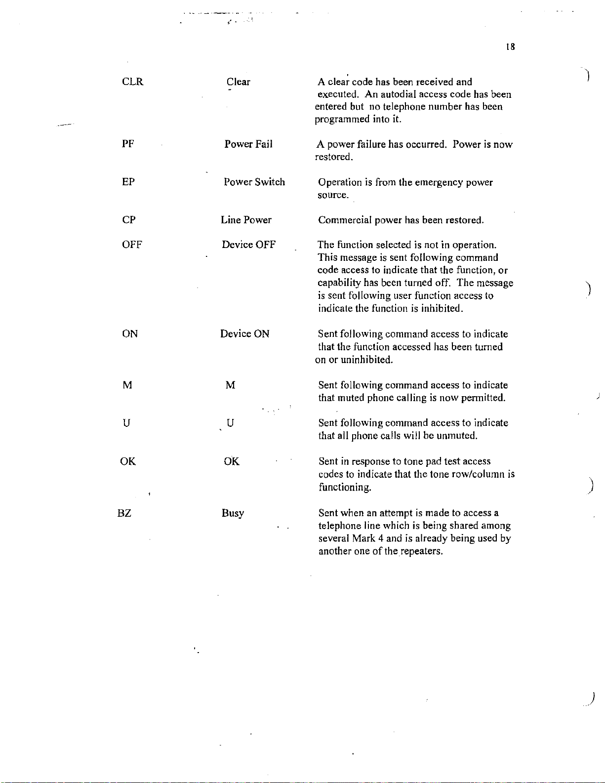
CLR Clear
PF Power Fail
EP Power Switch Operation
CP
OFF Device OFF The function selected is not
ON
Line Power
Device ON
A clear code has been received and
executed. An autodial access code has been
entered but no telephone number has been
programmed into it.
A power failure has occurred.
restored.
is
from the emergency power
source.
Commercial power has been restored.
is
This message
code access to indicate that the function,
capability has been turned off. The message
is
sent following user function access to
indicate the function
Sent
following command access to indicate
that the function accessed has been turned
on or uninhibited.
sent following command
is
inhibited.
Po\ver is
in
operation.
)
nO\V
or
)
M
M
u u
OK OK
BZ
Busy
Sent following command access to indicate
is
that muted phone calling
Sent following command access to indicate
that all phone calls will be unmuted.
Sent
in
response to tone pad test access
codes to indicate that the tone row/column
Sent when an attempt
telephone line which
several Mark 4 and
another one
of
is
the repeaters.
now permitted.
is
made to access a
is
being shared among
already being used by
)
is
) functioning.
)
19
)
)
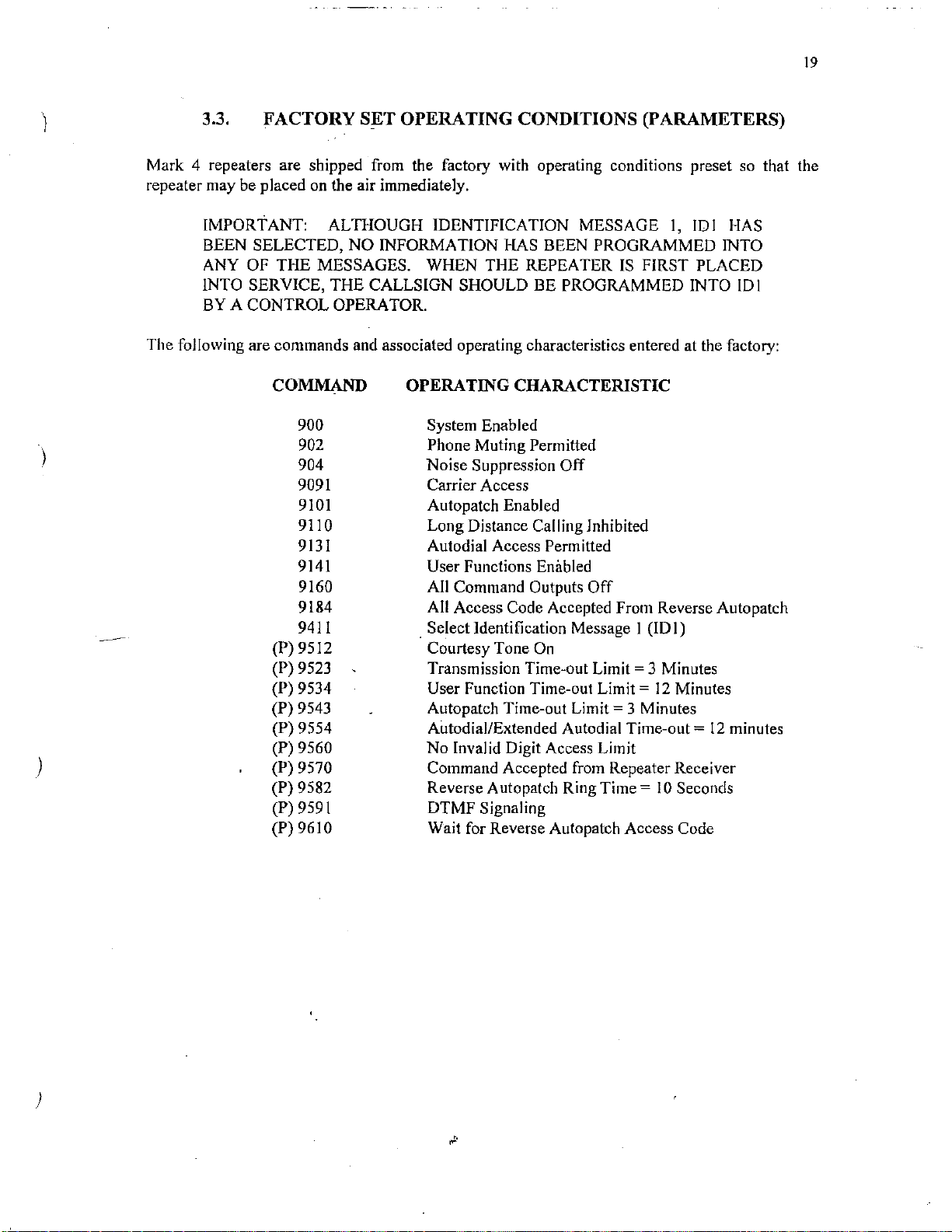
Mark 4 repeaters are shipped from the factory with operating conditions preset so that the
repeater may be placed
The following are commands and associated operating characteristics entered at the factory:
3.3.
IMPORTANT: ALTHOUGH lDENTIFICATION MESSAGE I,
BEEN SELECTED, NO INFORMATION HAS BEEN PROGRAMMED INTO
ANY OF THE MESSAGES. WHEN THE REPEATER
INTO
BY A CONTROL OPERATOR.
FACTORY
on
S;ET
OPERATING CONDITIONS (PARAMETERS)
the air immediately.
IOI
IS
FIRST PLACED
SERVICE, THE CALLSIGN SHOULD BE PROGRAMMED INTO
COMMAND
900
902
904
9091
9101
9110
9131
9141
9160
9184
9411
(P) 9512
(P) 9523
(P) 9534
(P) 9543
(P) 9554
(P) 9560
(P) 9570
(P) 9582
(P) 9591
(P)9610
OPERATING
System Enabled
Phone Muting Permitted
Noise Suppression
Carrier Access
Autopatch Enabled
Long Distance Calling Jnhibited
Autodial Access Permitted
User Functions Enabled
All Command
All Access Code Accepted From Reverse Autopatch
. Select Jdentification Message I (ID
Courtesy Tone
Transmission Time-out
User Function Time-out
Autopatch Time-out
Autodial/Extended Autodial Time-out=
No Invalid Digit Access Limit
Command Accepted from Repeater Receiver
Reverse A utopatch Ring
DTMF Signaling
Wait for Reverse Autopatch Access Code
CHARACTERISTIC
Off
Outputs
On
Off
Limit=
Limit=
Limit=
Time=
3 Minutes
12
3 Minutes
I 0 Seconds
I)
Minutes
12
HAS
!DI
minutes
)
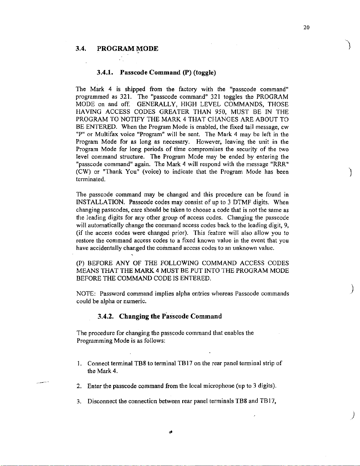
3.4. PROGRAM MODE
20
3.4.1. Passcode Command
The Mark 4
programmed as 321. The "passcode
MODE
HAVING ACCESS CODES GREATER THAN 950, MUST
PROGRAM TO NOTIFY THE MARK 4 THAT CHANGES ARE ABOUT TO
BE ENTERED. When the Program Mode
"P"
Program Mode for as long as necessary. However, leaving the unit in the
Program Mode for long periods
level command structure. The Program Mode may
"passcode command" again. The Mark 4 will respond with the message
(CW) or "Thank You" (voice) to indicate that the Program Mode has been
terminated.
The passcode command may be changed and this procedure can be found
INSTALLATION. Passcode codes may consist
changing passcodes, care should be taken to choose a code that
the leading digits for any other group
will automatically change the command access codes back to the leading digit,
(if
restore the command access codes to a fixed known value
have accidentally changed the command access codes to
on
or
Multifax voice "Program" will be sent. The Mark 4 may be left
the access codes were changed prior). This feature will also allow you to
is
shipped from the factory with the "passcode command"
and off. GENERALLY, HIGH LEVEL COMMANDS, THOSE
(P) (toggle)
command" 321 toggles the PROGRAM
BE
is
enabled, the fixed tail message, cw
of
time compromises the security
be
ended by entering the
of
up
to 3 DTMF digits. When
is
not the same
of
access codes. Changing the passcode
in
the event that you
an
unknown value.
IN
of
the two
THE
in
the
"RRR"
in
as
9,
--
(P) BEFORE ANY OF THE FOLLOWING COMMAND ACCESS CODES
MEANS THAT THE MARK 4 MUST BE PUT INTO THE PROGRAM MODE
BEFORE
NOTE: Password command implies alpha entries whereas Passcode commands
could be alpha or numeric.
THE COMMAND CODE IS ENTERED.
3.4.2. Changing the P·asscode Command
The procedure for changing the passcode command that enables the
is
Programming Mode
I. Connect terminal TBS to terminal TB
the
Mark4.
2. Enter the p·asscode command from the local microphone (up to 3 digits).
3.
Disconnect the connection between rear panel terminals TBS and TB 17,
as follows:
17
on
the rear panel terminal strip
of
)
)
21
3.5.
In
the following discussion, Tables 3.1, 3.2 and 3.3 on pages 27, 28, and 31, respectively, will be
used. For CW and Multifax, all words, numbers, and
is
code
programmable repeater messages may consist
messages that may consist
IN
NO SPACES SHOULD BE PROGRAMMED UNLESS THEY ARE NEEDED TO SEPARATE
WORDS.
I message character. Any code above 254
ALL EXAMPLES BELOW, SPACES HAVE BEEN USED FOR CLARITY IN READING.
MESSAGE
of
PROGRAMMING
of
up to
19.
fetters are made
in
the Word List
up
to 9 message characters except identification
up
of
a 3 digit code. Each
is
two character spaces. All
3.5.1. Designing the Message
Suppose we wish to inform repeater listeners that a NET will be meeting tonight.
Let's design the message
CW MESSAGE: Looking in Table 3.1, we find that the corresponding 3 digit
"N"
is
code for
"NET" message:
the
023, "E"
"NET".
is
014, and "T" is 029. Putting them together designs
(3
message characters)
023
0 l 4 029 (translated: NET)
)
MULTIFAX MESSAGE: Looking
3 digit code for the word
message character) ·
MESSAGE MASTER REAL-VOICE
will first have to record the message
49) are available for recording. Let's use track
MEETS TONIGHT".
access code to record a voice track
access code 945 I 0 and immediately without releasing the PTT button, we speak
the message
When the
acknowledgment that it was recorded.
played by using the PLAY
be
94710.
946. On track
"NET MEETS TONIGHT".
PTT button
lfyou
wish
1.0,
the access code would be 94610.
)
"NET'.'
201
We have up to 30 seconds
94510
is
released, the message will be played back
MESSAGE command, 947. On track
to
erase a message, the ERASE MESSAGE command
94510
94610 erases message
94710 plays message
in
Table 3.2, we find that the corresponding
is.201. Therefore, our Multifax message
(translated: NET)
MESSAGE~
in
our own voice. Fifty voice tracts
is
945. So, to record
~peak
Message
If
desired; the message can again be
records message
on
To design this message we
10
to
record the message "NET
of
record time per track. The
on
track I
10,
on
track I 0
on
track I 0
track
10
0,
is:
(I
(OD
to
we use the
as
an
that would
is
r• ·
..
•o
22
Track
message design we
message is:
Thus far, we have designed three types
10
now contains our message. Since
must add a 0
in
front
(I message character)
.
010 (translated: Track
IO
message "Net Meeting Tonight"
of
of
messages.
we'
need 3 digit codes for our
the
10,
010. Our MM real-voice
3.5.2. Special Characters
Now that we have the design, we must tell the Mark 4 which
messages it will be sending: CW, Multi fax voice, or Message Master real-voice.
Table 3
EQUIPPED
USING SYNTHESIZED VOICE UNLESS
.3
on page 31 gives the set
of
special characters that
WITH THE MULTIFAX OPTION WILL SEND ALL MESSAGES
WE
TELL THE MARK 4
CHANGE ITS MESSAGE TYPE BY ENTERING ONE
CHARACTERS.
The special character for sending CW
is
090.
If
the unit
Multifax, we will need to precede our CW message design with 090: (four
message characters)
of
the 3 types
do
just
this. UNITS
OF
THE SPECIAL
is
equipped with
of
TO
090
023
014 029 (Translated: Send,
Since our message will be automatically sent
not need to precede our Multifax message with
Voice):
(1
message character)
20
I (Translated: Send, the message Net)
in
CW, the message NET)
in
Multifax voice, we do
094 (send Multi fax
The special character for sending Message Master voice tracks
Message Master real-voice message will be preceded
by
095:
characters)
095 O I 0 (Translated: Send,
in
MM real-voice, voice track I 0 message,
Net Meets Tonight)
So far, we have designed the message and told the Mark 4 how
to
is
095. Our
(2 message
send
it.
)
)
23
.
\
3.5.3. Programming the Message
. -
Now
we
must program this message into one
can inform the repeater listeners. Let's choose Tail Message I (TM
TM!
access code 'for programming
characters but it is not a message character
MESSAGE PROGRAMMING
ALL
THE
MARK 4 THAT
message character.
To program our
926
To program our Multifax message into
926
To program
CW
090 023 014 029# (Translated: Via
20
I#
(Translated: Via
our
MM
THIS
IS
message into
message into
is
MUST
THE
TM!:
message NET, end
TM!,
TM!:
of
the repeater messages so that we
926 and must now precede the special
END WITH A "#" TO INFORM
END OF
(4 message characters)
TM!:
send the message Net, end
(2 message characters)
THE
ENTRY.
TM!,
send
of
entry)
(I message character)
in
The
CW
# is not a
the
of
entry)
I). The
926 095
010# (Translated:
Via
end
TM!,
of
entry)
send in
MM
real-voice, track
IO
message,
3.5.4. Combining Message Types
All three types
the following manner: (8 message characters)
of
our message may be combined and programmed into TM 1
in
)
926
090 023 014 029 094 201 095 010#
Here
we
must use 094 to niake the switch to Multifax voice.
Via
TM!,
(Translated:
voice, the message NET, then send in MM real-voice, voice track
(Net Meets Tonight), end
send in
of
3.5.5. Deleting a Message
We can program the same Tail Message as above with a different message and
this will automatically delete the previous message
follows:
CW,
entry)
the message NET, then send
or
we
can simply delete
in
Multifax
I 0 message
it
as
)
926#
24
3.5.6. Special_
Special character 096 allows Multifax readouts to be included
message characters are found
For example,
and temperature we would enter:
If the informational message
when accessed
The temperature
Multifax clock and the temperature
converter number
if
we wish to program the Information Message to give both time
935
096
001
002 causes a temperature message
by
is
Character
in
is
the command to program the informational message
is
the special message character
causes a clock time message
is
a user (access code 508) will
83
degrees." The time given
l.
Messages (Multifax)
Table 3.2, beginning
935 096
programmed
001
002#
to
in
this manner, the message heard
be:
in
is
derived from the input to analog/digital
on
Page 28.
be sent
to
be sent
"The time
the message
in
messages. The
is
six thirty AM.
is
taken from the
3.6.
We wish to program the Informational Message
Severe
we find the 3-digit message code for DANGER
THUNDERSTORMS
Message
Here we do not need the special character, 094, because units equipped with
Multifax will automatically send voice unless we tell
The Courtesy Tone may be programmed
unit
OTHER
3.6.1.
Thunderstorms" using Multifax voice. Looking
is
935.
3.6.2. Courtesy
IS
NOT EQUIPPED with Multifax:
PROGRAMMING EXAMPLES
Informational
is
075. The access code
Message
935.
067 079 075#
Tone
to
be the CW letter K as follows
937
020#
to
give a warning "Danger
in
Table 3.2
is
067, SEVERE
to
program the Information
it
otherwise.
on
is
Page 27,
079, and
if
the
)
)
25
937
is
'
I
the Program Courtesy Tone access code and 020
for the CW letter
K.
· -
is
the message character
The Courtesy Tone may be programmed to be the CW letter K
IS
unit
In
message
Analog/digital converter 3
power. To clarify the quantity that
access this reading, we can program analog/digital Converter 3 message
)
"Watts" in the following manner:
942
message
Watts",
EQUIPPED with Multifax:
090 020#
937
this case, the special character must be included
in
CW and not voice. ·
3.6.3. Analog/Digital
is
the access code to program
"Watts". The user accessing this reading would hear, for example, "12
12
being the analog/digital converter value.
Converter
is
appropriately connected
is
being measured to the repeater users who
942 060#
AD3
message and 060 will give the voice
to
(MF)
tell the Mark 4 to send this
to
as
follows if the
measure repeater output
to
be
3.6.4.
We
wish to program Identification message
deliver a recorded message. We know that this recorded message can be
accessed through
)
922
is
the access code to program 102,
output pulses to be sent
which pulses User Function
3.6.5.
Special character 092 allows DTMF tone burst
may
be
used for remote signaling. DTMF tones sent are determined by the 3
digit sequences entered following the special character.
Output
User Function
DTMF
Pulselnduded
in
Outputs
In
5.
Our command sequence
922
091
001#
091
messages, and 00 I
5.
Message
to
trigger
is
the special character
is
the special character message
to
be sent during messages which
an
external device
is:
to
to
allow

In
Summary
26
All messages entered into the Mark 4 must consist
First, access code to program a certain message (this
Next, up to maximum allowed message characters (none
Next,#
to end the entry (this is not a message character).
of
the following:
is
not a message character);
if
deleting);
)
)
)
27
)
)
3.7.
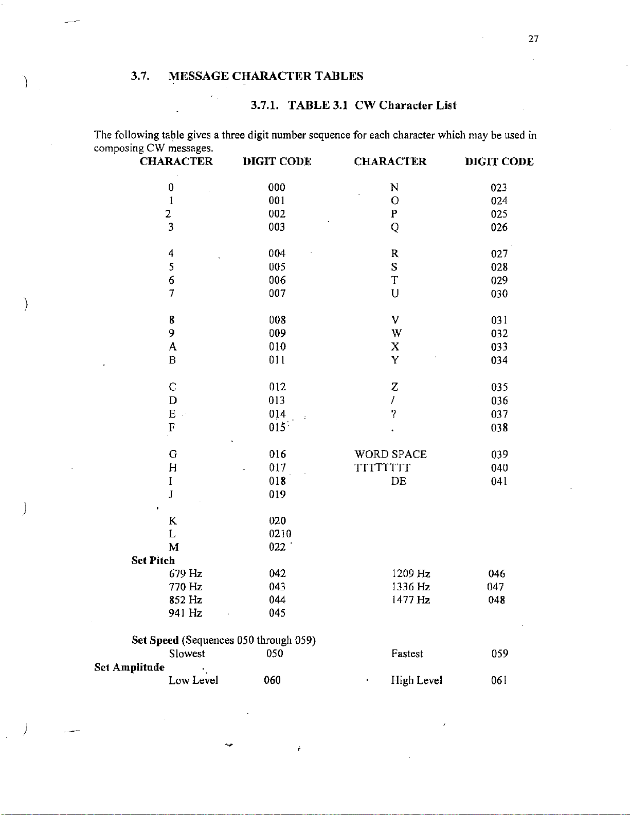
The following table gives a three digit number sequence for each character which may be used
composing
MESSAGE
CW
messages.
CHARACTER
3.7.1.
TABLE
TABLES
3.1
CW
Character List
CHARACTER DIGIT CODE CHARACTER DIGIT CODE
0 000 N 023
1
2 002
3 003 Q 026
4 004
5 005 s 028
6
7 007
8 008 v
9
A 010 x 033
B
001
0
p
024
025
R 027
006 T
029
u 030
03
009 w 032
Oil
y
034
l
in
)
Set Pitch
Set Speed (Sequences 050 through 059)
Set Amplitude
c 012 z 035
D
E
F 015
G
H 017
J 019
K 020
L 0210
M
679 Hz 042 1209 Hz
770 Hz 043 1336 Hz 047
852 Hz 044 1477 Hz 048
941
Hz 045
Slowest
Low Level 060 High Level
013
0)4
016 WORD SPACE
TTTTTTTT
018
022'
050
I
? 037
DE
Fastest
036
038
039
040
041
046
059
061
)

28
3.7.2.
Multifax Word List
Software Version 3.6
(f) indic'.'tes word in female voice
010
A
326 A
100
246
192
193
211
194 adjust
212 affirmative
321 afternoon
661
066
086
601
055 alternate
062
419
084
169
129
027
359
089 at 604 clock
379 at (f)
008
303 ate (f)
201
130
011
342
199
406 base (f)
199
406 bass (f)
011
342 be
011
342 bee
161
131
662
132 bravo 142 daze 216 failure
(f)
AM
AM
(f)
abort
about
action
(f)
air
alert 050 call
all 378 call
alpha 135 cancel
amps 664 ceiling
amateur
and
answer 603 Charlie
area 123
are
are
ate 196 code
auto
automatic
B 047 control 610 equal
B (f) 412
base
bass
be
(f)
(f)
'
(f)
bee 013
(f)
below 067 danger 015
between
blowing
133 brake
133
break
159 broken
602 button
186 buy
186
by
186 bye
012
c 143
343 c (f)
134 calibrate
(f)
caution
136
Celsius
665
137 change
check ·
circuit
138
081
clear
·335
club
407 code (f)
complete
139
140
connect
213 contact
control
crank
605
currant
160
026 cue 215 evacuate
cue
358
141
cycle 018
(f)
(f)
D
344
D (f)
day (f)
323
142 days 190
~
space between words is 254
666 decreasing
082 degree
606 delta
036 device
202 dial
051
direction
607 display
667 divided
door
404
door (f)
144 down
668 drizzle
410 dues (f)
669 dust
014
E
346
E (f)
070
east
608 echo
008 eight (8)
303
eight (8) (f)
110 eighteen 18)
313 eighteen (
118 eighty
609 electrician
eleven (11)
103
306 eleven
214 emergency
enter
037
670 equals
error
122
671
estimate
322 evening
eye
350
eye
(f)
61
I exit
F
F (f)
347
fail
(80)
(I
J)(f)
18)
)
(f)
)
)

29
j
,\
)
Multifax word list continued
672 Fahrenheit
182 fast 349
613 feat
403 feat (f)
613
feet
403 feet (f) 206
217 filed 218
107 fifteen (15)
310
fifteen (15)
115
fifty (50)
318 fifty
054 fire
005 five (5)
300 five (5) (f) 064
614
162
004 for
004 fore 128
253 fore (f) 382
004 four (4)
253
114
317
106 fourteen (14)
309 fourteen (14) (f)
615
077 freezing
045
373 Friday
038 from
016 G 381
348
617 gait 622 India
616 gallons 679 indicated
617
618 gauge 623 inspector
016 gee 040 intruder 320 morning (f)
348
619
052
388 go(t)
324 good (t) 351 J
133
332 great
175
673 Greenwich 352
(50) (f)
flow
fog
four (4)
forty (
forty (
foxtrot
frequency 676 ice
G
(f) 677 increasing 682 missed
gate
gee
(t)
get 245 is
go
great 624 Juliet 355
green
(t)
(t)
40) 120 hundred (100)
40)
(t)
(f) 220 identify
(f)
017 H 148
H(t)
078 hail
163
half
207 ham
ham fest
have 146 light
325 have (t) 625
675 haze 124
083
heavy 063 low
621 Henry
056 hertz
064
hi
high 354 M (f)
402 high (f)
219 hold
383 home
188
339 hours (t) 059 mega
376 hundred ( 100) (f) 057
056 hurts 627 micro
018 I
350 I
221
187
222
085
019
020 K 405
058 kilo
(f) 626
hour 147
hour
(t)
hours
(t)
immediately 179
m 409
in
(t)
information 369 Monday
is
(t)
J
(t)
K(t)
knot
021
L
353 L (t)
680 land
145
left
lima
line
401 low (t)
022
M
039 machine
331 machine
manual
measure
337 meeting
414 meeting
209
messages
meter
628 mike
681
miles
629
mill
milli-
630
660 million
minus
minute (t)
168
minutes
682 mist
683 moderate
165 more than
631
motor
632 move
684 moving
023
N
N (t)
148 naught
naught (f)
223
negative
336 net
(f)
(f)
(f)
-

30
Multifax
417
328 night
009
304 nine
I I I
314 nineteen (19) (f)
119 ninety
224
068 North
148
405
639 number
024
356
686
685
248 o'clock (f)
087
041
386
389
024
249
635 ohms
042
385 on (f)
001
250
088 open
377
048
180
128
382
188
339
126
189
687
025
357
IOI
247
636
word
list
continued
net (f)
nine (9)
(9)(f)
·
nineteen (19)
(90)
110
not
not(f)
0
0 (f)
obscured
o'clock
of
off
off
(f)
office (f)
oh
oh
(f)
on 643 push
one
(I)
one
(l)(f)
open (f)'
operator
Oscar 359
our
our (f)
ours
ours (f) 152 range
out
over 174 red 074 storm
overcast
p
p (f)
PM
PM
(f)
papa 227
688 partially
637 pass
149 passed
149
past
203 patch
413 pay (f)
689 pellets
700
per
408 per (f)
638 percent
204 phone
411
phone (f)
639 pico
416 please (f)
178
plus
061
point
208 police
150 position
043 power
400 power (f)
197
practice
640 press
151
pressure
641
probe
·240
program (f)
642 pull
026 Q
358 Q (f)
Quebec
644
027 R
R(f)
radio
205
radios
226
rain
073
ready
065
remote
198
repair
177
repeat
044
241
repeater
418 repeater (
153
right 649 tango
Roger
f)
645 Romeo
028
s
s (f)
360
170
safe
sand
701
374 Saturday(f)
702 scattered
012 sea
343 sea (f)
sealing
664
012 see
see (f)
343
646 seconds
228 security
229 select
154
set
007 seven (7)
seven (7) (f)
302
109 seventeen (
312 seventeen (17) (f)
117 seventy
severe
079
166 showers
shut
155
sierra
647
six (6)
006
301
six (6) (f)
sixteen ( 16)
108
311
sixteen ( 16) (f)
116
sixty (60)
703 sleet
181
slow
648 smoke
072 snow
069 South
speed
183
156
start
157
stop
375 Sunday (f)
125
switch
029 T
361
T (f)
029
tea
17)
(70)
i
)
)

•
31
)
)
)
Multifax word list continued
361 tea
191
l
02 ten (JO)
305 ten (10) (t)
053 test
238 thank (t)
046 the
330 the (t)
704
705 thinly
003 three (3)
252 three (3) (t)
105
308
113 thirty (30)
(t)
316
334 this
242
600 thousand
341
372
075 thunderstorms
121
244 time
049 timer
706 times
002 to
327 to
380 today
195 tomorro\v
338 tonight
002 too
327
650
076 tornado
231 traffic
370
707 turbulence
171
384
104 twelve (12)
307
112 twenty (20)
315 twenty (20) (f)
002 two (2)
251
(t)
temperature
thin
thirteen ( 13)
thirteen (13)
(30)
thirty
this is
thousand
Thursday
time
(J)
(t)
(t)
(t)
(t)
(t)
(t)
too (t)
tool
Tuesday
turn
turned (t)
twelve (12) (t)
·two (2) (t)
(t)
(t)
. .
030
u 365 x
u (t)
362
158 up
651 under
652 uniform
653 unit
708 unlimited
232 use
233 use (verb)
031
v
363 v (t)
variable
709
654 valve
234 verify
655 Victor
710 visibility
127 volts
032 w
364 w (t)
wait
172
. 235
warning
236 watch
060 watts
237 way
167 weather
371 Wednesday ( t)
333
week
(t)
172 weight
200 welcome
329 welcome (t)
071
west
167 whether
656 whiskey
71
l white
034 why
won
words
write
(t)
(t)
366 why
210 will
080 wind
001
250 won (t)
340
153 wright
153
033 x
(t)
X-ray
657
y
034
y
366
658 Yankee
176 yellow
030
362 you
415
035 z
367
000 zero (0)
368 zero
659 Zulu
(t)
you
your
z (t)
(t)
(t)
(0)

32
3.7.3.
The following list
be
sent. They may be used to switch between types within messages.
Special charactet
output to be pulsed during messages.
The special character 096 followed
message to be included
Special
Character
090
091
SPECIAL
of
special characters are used to tell the Mark 4 which types
09 l followed
in
messages.
CHARACTERS
by
any
of
the digit sequences will cause the respective logic
by
any
of
the digit sequences will cause their respective
Action
Begin sending
Toggle logic outputs
Digit
CW
Sequence
001
002
003
004
005
of
Output
User function 6
User function 7
User function 8
User function 9
User function I 0
Pulsed
messages are to
)
092
093
094
095
096
Begin sending
Begin sending sequential tones
Begin sending Multifax voice
Begin sending Message Master voice tracks
_Begin
sending special message
Digit
000
003
DTMF
Sequence
001
002
004
digits
Reading
Receiver readout
Greeting followed by
is" followed by the time
female voice
Message, 11The temperature is
XX
degrees." XX is a reading
based on analog/digital
converter input
Analog/digital converter 2 input
scaled to the range
Analog/digital converter 3 input
scaled to the range
"the time
I.
0-120 volts.
0-120.
in
)
a
)

33
098
005
006
007
008
009
Begin sending callsign list.
000
001
Analog/digital converter 4 input
scaled to the range
0-25.
Analog/digital converter 5 input
of
scaled to the range
0-25.
Time in a female voice.
Time
in
a male voice.
"The time is" followed by the
in
time
Send
a male voice.
callsign list - quit,
if
no
message exists.
"No Messages"
Send
if
no
message exists.

3.8. BASIC REPEATER OPERATION
34
3.8.1. System EnablefDisable (Toggle)
The command disables repeater transmitter operation and all user functions. The
in
command operates
the repeater system
system
disabled and incoming telephone calls answered for the purpose
commands.
This
will be found in INSTALLATION
is
enabled. Command access codes are accepted when the sysiem is
is
used for testing and alignment
a toggle fashion. The first time the command
is
disabled and the next time the command
90 I Test Mode
of
the Mark 4 and
& MAINTENANCE.
3.8.2. Noise Suppression (Toggle)
When this command code
"ON"
in
CW or "DEVICE ON"
respond with
suppression filter ON, the additional noise rejection causes a slight delay
response to a valid signal. Therefore, under normal propagation conditions,
suggested that the filter not be used.
"OFF"
is
entered, the Mark 4 will respond with a message
in
voice. Entering
in
CW or "DEVICE OFF"
C\
.P
is
its
procedure and use
qv\
it
again, the Mark 4 will
in
voice. With the noise
is
entered,
entered the
of
receiving
in
it
the
is
)
~
3.8.3.
This command removes two
Mark 4 to indicate
and
Switch" will be present whenever the Mark 4
powe~
11
"CP
and may not be removed with this command.
Clear Control Message
abnormal power or other abnormal operating conditions, "PF"
or "Power Fail"
and 11Line Po\ver
of
the three fixed tail messages generated by the
0 5
11
• The message
is
operating
"EP"
frorri
or 11Po\ver
emergency
3.8.4. VOX Operation (Toggle) qtil.
When using VOX operation, the Mark 4 will not respond to unmodulated
received carriers. When
only operation.
VOX operation
is
off, the repeater will be
in
a carrier-
)
)
'

35
\
I
the Message Master could get disturbed by a power transient which does not
affect the Mark 4 processor board microprocessor.
occur,
respond to access codes for recording and playing speech. The Force Processor
Reset command is provided to remedy this condition by forcing both
microprocessors to reset. Procedure for use
enter 907 and wait
restored and PF or Power Fail message will be sent
The following commands determine the conditions that must be met by a
received signal for normal repeater operation (re-transmission
signal). These commands
means that user functions, such
operation
repeater
3.8.S.
It
the Mark 4 would operate normally but the Message Master would not
3.8.6.
in
Force
is
theoretically possible, though unlikely, that the microprocessor
Repeat
is
disabled. Further restrictions can be also be added by setting the
VOX operation.
!'rocessor Reset (Message Master)
If
is
simply for a control operator
JO
seconds for reset cycle
Permissions (Modes
do
not affect the operation
as
autopatch, may sti
to
complete. Operation will be
on
tail.
of
Access)
of
II
this condition were to
of
a received
user functions. This
be used even
if
in
to
repeat
9090 Repeat Operation Disabled
9091 Carrier Access (open repeater)
9092 CTCSS required for repeat operation
9093 DTMF Wakeup (access under USER FUNCTION control)
9094 CTCSS or DTMF Wakeup (either)
3.8.7.
The following commands set the nominal speed for all CW messages:
Set
CW
Message Speed
9170 through 9179: Command 9170
91
79
is
fastest
is
slowest
3.8.8. Select Callsign Identification Message
Five different callsign identification messages may be stored simultaneously
the Mark 4. The selected callsign message wil I be used whenever the repeater
inactive. When the repeater
will automatically be substituted as was described
FEATURES section.
is
active, call sign identification message
in
the REPEATER
I,
!DI,
in
is

36
9411
Select callsign identification message I,
Select callsign identification message
9412
9413 Select callsign identification message 3,
9414 Select callsign identification message
9415 Select callsign identification message 5,
3.8.9. Program Identification Message
The following commands allow the information
entered. The maximum number
recommended that !DI message
see pages 3-5, 3-9, and 3-12).
921
Program identification message
922
Program identification message
923
Program identification message 3,
924 Program identification message
925 Program identification message
of
message characters allowed
be
very brief (callsign letters only and
I-,
2,
4,
5,
3.8.10. Tail Descriptions
ID
1
2,
!02
!03
4,
!04
IDS
in
identification messages to
ID!
!02
!03
!04
IDS
is
19.
in
be
It
CW -
)
is
)
(P) 9510 No tail. Repeater transmitter ceases immediately when
received signal ceases. No tail or acknowledgment
messages are sent.
(P)
9511
Quiet 5-second tail
(P) 9512 Courtesy tone (message) on/off (toggle)
(P)
9513
Tail Message I
(P) 9514 Tail message 2 (TM2) sent following the tail. (toggle)
(P) 9515 Tail message 3 (TM3) sent following the tail. (toggle)
Only one
another tail message
messages are sent I
brief transmissions.
of
the three tail messages
0 seconds after the repeater tail. They are not sent following
will automatically deselect any prior selection. Tail
(TM\)
may
sent folio.wing the tail. (toggle)
3.8.11. Program Tail Messages
The following commands allow information
and stored
in
memory. The maximum number
926 Program tail message I, TM!
927
Program tail message 2, TM2
928
Program tail message 3,
TM3
be selected at any time. Selecting
to
be
entered into the tail messages
of
message characters
is
9.
)
)

37
3.8.12.
Many repeaters use a courtesy tone
transmission time-out timer has been reset.
be programmed to be a single tone
command allows the desired message to be entered into the courtesy tone. The
maximum number
Program
of
Courtesy
message characters
937
Tone
to
indicate
In
or
a lengthier message. The following
is
9.
Program Courtesy Tone, CT
to
the Mark
repeater users that the
4,
the courtesy tone
may
3.8.13. Transmission Time-out Limit
The following commands select the time-out limit for transmission length.
(P) 9520 No time-out limit
(P) 9521 1 minute time-out limit
(P) 9522 2 minute ti.me-out limit
(P) 9523 3 minute time-out limit
(P) 9524 4 minute time-out limit
(P) 9525 5 minute time-out limit
(P) 9526 6 minute time-out limit
(P) 9527 7 minute time-out limit
(P) 9528 8 minute time-out limit
(P) 9529 9
mi_n_u,te
time-out limit
3.8.14.
A time-out message is sent whenever the transmission time-out limit
It
is
sent immediately before the transmitter
a time-out has occurred, and
inform the user who caused the time-out.
The following command allows a message
time-out message. The maximum number
3.8.15. Invalid Access
The following commands set the number
allowed before
Program
936 Program Transmission Time-out Message, TO
Transmission Time-out Message
is
turned
it
is
sent again when the received signal ceases
to
of
message characters
off
be entered into the transmission
Limit
of
invalid DTMF digits that are
:urther access attempts are ignored
9560 No limit
9561
8 invalid digits allowed
9562
12
invalid digits allowed
..
to inform listeners that
is
is
exceeded.
9.
to

9563
16
invalid digits allowed
9564
20 invalid digits allowed
24
9564
invalid digits allowed
3.8.16. Command Access from Repeater Receiver
These commands cannot be entered from the repeater receiver.
9570 Commands accepted from repeater receiver
957 l Commands accepted from repeater receiver
9572 Commands not accepted from rep.eater receiver
if
CTCSS
is
present
38
These commands
do
not affect the local microphone.
3.9. TELEPHONE INTERCONNECT COMMANDS
3.9.1.
When this command
indicate that transmission
user desires
with the letter
all
future telephone calls will be unmuted.
Phone Muting Permission (toggle)
is
entered, the repeater responds with the letter M to
of
receiver audio during phone calls may
to
do so. The Mark 4 responds
U indicating that
.the
muting capability
to
the second entry
is
no
longer available and
be
muted
of
this command
if
3.9.2. Repeater Monitoring
To monitor repeater activity from the autopatch telephone line, the command
must0be entered from the autopatch telephone line. When the command
entered, audio from the repeater receiver will
period
transmitter. Monitoring may be terminated before the 2 minute time limit by
entering the autopatch clear code.
of
2 minutes. Phone line audio will not be routed
be
routed
to
the phone line for a
to
the repeater
a
)
is
3.9.3. Dialing Type
The type
autopatch, autodial, and extended autodial. When the Mark 4
the factory,
of
dialing selected using these commands
it
is
'set for the DTMF dialing.
9590 Select dial pulse signaling
9591 Select DTMF signaling
is
used for originated calls;
is
shipped from
)

3.10. AUTOPATCH
3.10.1. Auto patch Operation
39
The following commands set the conditions that must
redial access. They do not affect reverse autopatch, autodial, or extended
autodial access.
9100 Autopatch disabled (access inhibited)
9101 Autopatch enabled (access permitted)
CTCSS required for autopatch access
9102
be
met for autopatch and
3.10.2. Select Autopatch/Redial Time-out Limit
(P) 9540
(P)
(P) 9542 Autopatch time-out
(P) 9543 Autopatch time-out
(P) 9544 Autopatch time-out
(P) 9545 Autopatch time-out
(P) 9546 Autopatch time-out
(P) 9547 Autopatch time-out
(P) 9548 Autopatch time-out
(P) 9549 Autopatch time-out
No
autopatch/redial time-out limit
9541
Autopatch time-out
limit=
limit=
limit=
limit=
limit=
limit=
limit=
limit=
limit=
I minute
2 minutes
3 minutes
6 minutes
9 minutes
12
minutes
15
minutes
18
minutes
usage sensitive
3.10.3. Autopatch Dialing Restrictions
The following commands allow restrictions to
dialing with the primary autopatch. They
autod,ial or extended autodial operation.
9110 Long distance calling restricted. Calls having a 0 or I as the
first digit will be blocked. Dialing more than 8 digits will cause
the call to be canceled.
9111 Calls may have only
numbers will be accepted.
9112 Calls may have 1 or 0 as the first digit and may have more than
8 digits
9113 Calls may have 1 or 0
8 digits
9114 No dialing restrictions.
ifCTCSS
if
the command signal
I as the first digit. No more than 8 digit
is
present.
as
the first digit and may have more than
do
is
be
imposed on long distance
not affect predial-autopatch,
present (see 9112 above).

40
3.10.4. Progr_amming Prohibited Telephone Numbers
(P) 974 Program prohibited telephone number 1
(P) 975 Program prohibited telephone number 2
(P) 976 Program prohibited telephone number 3
(P) 977 Program prohibited telephone number 4
(P) 978 Program prohibited telephone number 5
These commands allow autopatch telephone calls to specific telephone numbers
or calls to specific calling areas to be blocked. Each
up
contain
with the autopatch and redial access codes, not autodial or extended autodial.
For these commands
(P). .
If
we want prohibited telephone number 1
Prohibited Telephone Number I access code, 974, must
number we wish to prohibit followed by
to 7 digits. Prohibited telephone numbers only block calls originated
to
be accepted, the Mark 4 must be
to
a#.
974 555 1234#
of
the above codes can
in
the Program Mode
be 555-1234, the Program
be
followed by the
l
)
'
lfwe
wish to block the whole 555 calling area, then:
974 555#
3.10.5. Programming Predial Autopatch Digits
(P) 962 PROGRAM FIRST PREDIAL AUTOPATCH DIGITS
963
(P)
As
was described
prefixes to telephone numbers can be programmed into the
so as to reduce the number
telephone call. For example,
exchange 362, then the predial autopatch access code entered
automatically dial the 362 and the user only need
The predial autopatches may contain a maximum
an
area code and a telephone office code (e.g. 212 362). To program predial
autopatch digits a control operator should enter the command access code
followed by the digits to be programmed followed by a #. For example,
program the first predial autopatch with the digits 362 would be done as follows:
PROGRAM SECOND PREDIAL AUTOPATCH DIGITS
in
the REPEATER FEATURES section
of
digits which repeater users must enter
if
telephone calls are frequently made to telephone
to
enter the rest
of
6 digits so they may contain
of
this manual,
Predial Autopatches
to
place a
by
a user will
of
the number.
to
)
962 362#
)

Do not put spaces between numbers when they are being entered into the Mark
4.
The first and second predial autopatch programming codes operate
manner.
-
in
the same
3.11. AUTODIAL
3.11.1. Autodial Operation
The following commands set the conditions that must be met for autodial access.
These commands do not affect extended autodial operation.
9120 Autodial disabled (access inhibited)
9121 Autodial enabled (access permitted)
9122 CTCSS required for autodial access
3.11.2. Extended (User) Autodial Operation
41
The following commands set the conditions that must be met for extended
autodial access:
9130 Extended autodial disabled (access inhibited)
913 I Extended autodial enabled (access permitted)
9132 CTCSS required for extended autodial access
3.11.3. Select Autodial/Extended Autodial Time-out Limit
'
/ (P) 9550
(P) 955 I Autodial time-out
(P) 9552 Autodial time-out
(P) 9553 Autodial time-out
(P) 9554 Autodial time-out
(P) 9555 Autodial time-out
(P) 9556 Autodial time-out
(P) 9559 Autodial time-out
3.11.4. Programming Autodial/Extended Autodial Telephone
Numbers
No
autodial time-out limit
limit=
limit=
limit=
limit=
limit=
limit=
limit=
3 minutes
6 minutes
9 minutes
I 2 minutes
I 5 minutes
18
minutes
usage sensitive

i'
42
When the Mark 4
extended autodial access codes are set
of
number
The Mark 4 must be
extended autodial telephone numbers so that
access codes for the purpose
When
precede the telephone number.
autodial access code
memory. Telephone numbers programmed may be
using two consecutive slots starting with an even-numbered slot). ALL
ENTRIES MUST END WITH#.
The following example illustrates the programming
1234 into extended autodial
autodial 754.
telephone numbers that may be simultaneously stored
Autodial functions 8 (12) (Begins with 810-822
Extended autodial (Group
Extended autodial (Group 2) 7 (100)
an
autodial number
is
shipped from the factory, the beginning digit
as
given below. Also given below, are the
1)
6 (100)
in
the Programming Mode
of
changing some information
is
being programmed, the autodial access code must
If
the Mark 4
is
entered,
it
will begin
700 and telephone number 555-6789 into extended
is
to
it
not
to
enter
or
knows
autodial
it
in
Program Mode when the
up
to
11
of
telephone number 555-
of
autodial and
in
each group:
change autodial and
is
going
to
receive
in
its memory.
an
old number
digits (or
22
in
digits
its
321
A control operator enters:
The repeater responds
Control operl!tor or
repeater user enters:
The repeater responds
Control operator or
repeater user enters: 754 555 6789#
The repeater responds repeats back the phone number
Control operator enters
The repeater responds :
In
this example, we programmed two extended autodial numbers, but when
the Program M?de any number
of
(enable the Program Mode)
"P" (CW) or "Program" (Voice)
700 555 1234#
repeats back the phone number
incorrect, it can be re-entered.)
321
(Program mode
"RRR" (CW) or "Thank You" (Voice)
telephone numbers may be programmed.
is
ended)
(If
the number was
)
in
if
no
Telephone numbers may be deleted
delete a number before entering a new number. Procedure
in
access code 700
is:
longer desired.
It
is
not necessary
to
delete the number
to
)

43
Enable
To check to make sure the number was deleted, access code 700 may
and the Mark 4 should respond with the message
P~ograrriMode,
321 - Enter 700# - Disable Program Mode,
"CLEAR".
be
entered
321
3.11.S. Voice Paging
This feature allows callers from the Reverse Autopatch telephone line
their telephone calls to specific repeater users with Multi fax voice paging.
For example, assume that autodial access code
WI XYZ. A caller
MicroFax voice message
transmitter
by
entering the access code 600 from the reverse autopatch telephone
on
the reverse autopatch telephone line can cause the
"CALL FOR WIXYZ" to be sent
assigned
to
on
600
is
line.
of
To use this feature, the callsigns
telephone numbers 600 through 799 must be programmed
each repeater user associated with autodial
i.nto
the Mark 4. To
program these callsigns, a control operator first places the repeater into the
"Enter ID" mode
should
NOT
this access code
message
"Enter ID".
by
entering the command access code 950
be
in
the Program Mode when entering this access code.) When
is
entered, the Mark 4 will respond on the repeater tail with the
I.
to
direct
repeater user
the repeater
(The Mark 4
Callsign identification information· can now be entered by entering the autodial
number
repeater users callsign followed
characters are those
callsign
where,
600
032
of
the repeatc;r user followed by the 3-digit message characters
giv_en
WIXYZ for user 600, enter:
is
the autodial code assigned
001
033
034 and 035 are the 3-digit message characters for WlXYZ from
in
Table
600 032
by
the # character. The 3-digit message
3.1
of
to
the user,
the manual. Thus,
001 033
034 035 #
to
of
the
program the
Table 3.1, and
# indicates that all the information has been entered.
Each callsign may contain a maximum
of
six characters (our example, WIXYZ,
contains five ch.aracters).

44
Callsigns may be entered for users
call signs have been entered, return the repeater to normal operation
the access code
9500 to end the "Enter ID" mode.
60
I through 799
in
similar fashion. When all
by
entering
3.11.6. Pause During Autodialing
Some telephone equipment requires a brief pause
an
calls to
be programmed into Mark 4 autodial numbers for use
Pauses may be entered when programming autodial phone numbers by using
touchtone
pauses can be generated by pressing the
Example: To program extended autodial user
95551212 with a 2-second pause following the digit
(Each•
above, is counted as a
12
digits, including pause characters, should be programmed as Long Autodial
Numbers.)
outside line. The Pause during Autodialing feature allows pauses to
• key. Each * entry generates a pause
• key repeatedly.
enter:
enter: 6009**5551212#
enter: 321
is
counted as a digit
321
by
the Mark 4, i.e., 9**5551212
I 0 digit number. Programmed numbers having more than
in
dialing when connecting
in
these applications.
of
about one second. Longer
600 with the telephone number
9:
(place Mark 4
(program telephone number
(end program mode)
in
program mode)
in
the example
)
3.12. REVERSE AUTOPATCH
3.12.1. Reverse Autopatch Operation
The following commands determine which access codes will be accepted from the reverse
autopatch telephone. COMMANDS
REVERSE
command input, or from the repeater receiver
command inputs).
AUTOPATCH TELEPHONE LINE. They may be entered locally, from the
9180 Incoming telephone calls not answered. (Neither
No commands
from the telephone line. The telephone line may
still be used for outgoing calls {autopatch, etc.})
9181 Command codes accepted from the telephone line.
User reverse autopatch alert code not accepted.
9182 Command access codes and user reverse autopatch
alert code accepted from the telephone line.
Other user function codes not accepted.
9180 AND 9183 MAY NOT BE ENTERED FROM THE
(if
the repeater receiver
or
user function codes may be entered
is
selected to accept
)
)

9183 User function access codes accepted from the
telephone line. Command access codes not
accepted.
9184 All command and user function access codes
accepted from the telephone I ine.
3.12.2. Phone Ring Time
45
The following commands set the length
will be allowed to ring before being answered by the Mark 4.
with the optional command telephone line interface, these commands also set the
ringing time before answer for incoming calls
(P) 9580 Answer immediately
(P) 9581 Wait 5 seconds before answering
(P) 9582 Wait
(P) 9583 Wait
(P) 9584 Wait
(P) 9585 Wait
(P) 9586 Wait 30 seconds before answering
of
time which incoming telephone calls
on
the command telephone line.
10
seconds before answering
15
seconds before answering
20
seconds before answering
25
seconds before answering
3.12.3. Reverse Autopatch Answering
The following commands determine the action that will be taken by the Mark 4 when
incoming (reverse autopatch) call
command 9180. After the call
the call will be automatically disconnected.
style should be selected. The alert signal sent
(P) 96 I 0 Wait for access code to be entered from
) telephone line. Ifreverse autopatch alert
access code
to the repeater transmitter.
is
answered. Reverse autopatch response
is
answered,
an
access code must
If
commands are to be entered, the first answering
by
the Mark 4 consists
is
entered, send the alert signal
be
On units equipped
an
is
also affected
entered within I 5 seconds or
of
a simulated ring.
by
(P) 96 I 1 Send
(P) 9612 Connect the telephone to the repeater
(P) 9613 Wait for reverse autopatch access code (505)
the
alert signal to the repeater
transmitter as soon as an incoming telephone
call
is
answered.
transmitter as soon as an incoming telephone
call
is
answered. Autopatch operation begins
immediately. No access code
no alert signal
or voice page code (600-799) then send alert
or page/alert.
is
sent.
is
necessary and

3.12.4. Command Line Interconnect
The optional Command Telephone Line Interconnect arrangement allows the
Mark 4 to be connected to a second telephone line exclusively for command
is
is
set
access. Command access is, therefore, guaranteed even when a telephone call
in
progress on the autopatch phone line.
in
The command line interconnect operates
Autopatch but only accepts incoming calls and
Phone Ring time is identical to that used on the autopatch phone line which
by command. After the Mark 4 answers, access codes may be entered for a
of
period
40 seconds and then the call will be automatically disconnected.
a similar manner to Reverse
is
not used for outgoing calls.
46
3.13. USER FUNCTION COMMANDS
The following commands do not affect telephone interconnect functions.
3.13.1. User Function Operation
9140 User functions disabled (access inhibited)
User functions enabled (access allowed)
9141
9142
CTCSS needed to access user functions
3.13.2. User Function Time-out Limit
The time-out warning sent
of
period
time-out can be extended for
repeater.
l 0 seconds prior to time-out. When usage sensitive timing
(P) 9530 No time-out limit
(P) 9531 3 minute time-out limit
(P) 9532 6 minute time-out limit
(P) 9533 9 minute time-out limit
(P) 9534
(P) 9535
°(P)
9536
(P) 9537
(P) 9538 24 minute time-out limit
(P) 9539 User function timing
by
the Mark 4 consists
45
seconds by a short burst
12
minute time-out limit
15
minute time-out limit
18
minute time-out limit
21
minute time-out limit
will not time out as long as repeater
of
periodic "beeps" for a
of
receiver signal to the
is
usage sensitive and
is
in
is
use.
)
)
selected,
)

47
\
3.13.3.
Of
the
12
User Function Outputs used for controlling external equipment, four
have programmable tail messages that are heard
present for 5 seconds
entered that will inform users that the function
message characters are allowed.
Example, User Function I controls a north facing antenna and User Function 2
controls a south facing antenna. The messages respectively could be CW
voice
"North" and CW "S" or voice "South". These messages will
the tai
I when either function
3.13.4.
The following command will allow information to be programmed into the
information bulletin that can be accessed by users. The maximum
characters are allowed.
Program
Program user function 1 message, UF I
929
930 Program
931
Program user function 3 message, UFJ
932 Program user function 4 message, UF4
Program
User Function Messages
if
received signal has been
or
longer. The following commands allow messages to be
is
active. A maximum
user function 2 message, UF2
is
active.
Information Bulletin Message
be
heard on
of
9 message
of
"N" or
9
935 Program Information Bulletin message,
3.13.5.
The f&llowing commands allow information to be entered into the Link messages
that will be heard
message characters is allowed.
Two links operating
by the user or connections between the two may be automatically done through
the Link Message.
Function Outputs, then, for example, LK2 message could be programmed to
activate both the link function and the user function output.
Program
on
Program Link l message, LKI
938
939 Program Link 2 message, LK2
on
If
Link
Messages
the tail when the link function
different frequencies can either be accessed individually
the relay to make this connection
is
IB
active. A maximum
is
in
one
of
the User
of
9

48
3.13.6.
Five analog inputs are available which may be used for monitoring other
equipment at the repeater site and may be accessed
can have programmable messages to help clarify the quantity that
measured.
degrees" and "Volts", respectively.) The linear scaling range
command below. The following commands allow information
these messages. A maximum
942 Program analog/digital converter 3 message,
943
944 Program analog/digital converter 5 message,
Example:
repeater output power, then message
"Watts". When this readout
respond with, for example,
Program
(ADI and AD2 have fixed messages
Program analog/digital converter 4 message, AD4 (0-120)
If
analog/digital converter 3
Analog/Digital
of9
message characters
is
AD3
is
accessed
"12 Watts".
Converter
of
appropriately connected
might
be
by
a user, the Mark 4 would then
Messages (Multifax)
by
all users. Three
"The Temperature
is
given after each
to
be entered into
is
allowed.
AD3
(0-120)
ADS
(0-25 )
programmed
as
of
these
is
being
is
XX
to
measure
the message
3.13. 7. User Mailboxes (Message Master)
Two
hu11dred
for each other. For ease
those used for the extended autodial capability. Typically, each repeater user
would be assigned
telephone number. These same access codes are used for that user's voice
mailbox.
different user mailboxes are available for users to record messages
of
use, these mailboxes use access codes similar
an
access code to contain his/her own extended autodial
(See page
7-3
and Page 7-4.)
to
)
3.13.8.
Voice storage capacity
speech.
after the messages are played. This can be done manually by the user or done
automatically using the Auto-Erase feature. This frees memory for later
AUTO-ERASE ONLY AFFECTS .USER MAILBOX MESSAGES AND DOES
NOT ERASE VOICE TRACKS RECORDED BY
The commands for enabling or disabling this feature are as follows:
Optimum use
Auto-Erase
of
the Message Master
of
this capacity requires that mailbox messages be erased
(P) 9810 Enable auto-erase feature
(P)
9811
Disable auto-erase feature
is
limited to 8 minutes
COMMAND.
of
real
use.
)
)

49
)
3.13.9. Set
Another means
mailbox messages with the following commands:
(P) 9820 User message recording disabled Inhibited
(P) 9821 8 second maximum record time
(P) 9822
(P) 9823
(P) 9824
(P) 9825
(P) 9826*.12 second maximum record time
(P) 9287
(P) 9828 8 second maximum record time
(P) 9829 16 second maximum record time
• Power reset uses this value
These commands only affect user mailbox record times. Voice tracks recorded
by
command always have a maximum time
Command Voice Tracks:
U~er
Message Maximum Record Time
of
conserving memory
(This also disables Echo function)
12
second maximum record time
16
second maximum record time
20 second maximum record time
second maximum record time
9
15
second maximum record time
is
to limit the maximum length
of30
MM
seconds.
SPEED
17
KHz
17
KHz
17KHz
17KHz
24KHz
24
KHz
24KHz
32KHz
32KHz
of
user
94500 - 94529 are fixed at 32 KHz
94530 - 94550 are fixed at
24
3.13.10. Erase Messages
The following commands allow erasing
voice tracks:
9480 Erase all user mailboxes
9481 Erase
all messages
of
all user mailbox messages and/or all
3.14. PERIODIC ANNOUNCEMENT
3.14.1. Periodic Announcement Message Interval
The following commands set the interval
message
is
sent. This message
9080 Send periodic announcement every
9081 Send periodic announcement every l /2 hour
9082 Send periodic announcement every hour
9083
Off
is
controlled
at
by
KHz
CO)VIMANDS
which the periodic announcement
the real-time clock.
15
minutes
(Multifax)
J

3.14.2. Program Periodic Announcement
The following command allows infonnation to be entered into this message.
This message may contain clock time announcement and/or any other message.
The maximum number
of
message characters
is
9.
3.15. COMMAND OUTPUTS
3.15.1. Setting Command Outputs (toggle)
50
The following eight commands toggle the state
COMMAND OUTPUT
SQUELCH
set at threshold and when the function is off, squelch is maximum tight. The
CW
message ON or voice message "Device ON"
enabled
"Device OFF" is sent when the output
command. These outputs have no time limit restrictions so they remain
chosen state until changed.
ON
MARK 4 REPEATERS. When the function is on, the squelch is
in
response to an entered command.
9160 Set all command outputs
9161 Toggle command output 1 (Squelch Adjustment)
9162 Toggle command output 2
9163 Toggle command output 3
9164
9165 Toggle command output
9166 Toggle command output 6
9167 Toggle command output 7 (Message CF? is sent on tail)
I
IS
USED
'Toggle command output 4
of
command outputs. TOGGLE
TO
REMOTELY CONTROL THE
is
sent when the output
CW
message "OFF" or voice
is
disabled
off
in
response to
5
an
is
entered
in
the
3.15.2. Program Comiµand Function 7 Message
)
)
The following command allows infonnation
notify that the function is active. The maximum number
9.
is
933 Program command function 7 message, CF?
to
be
entered into this message to
of
message characters
)

51
3.16.
CLOCK
CO~MANDS
(Multifax)
3.16.1. Set Real-Time Clock
This command sets the real-time clock on the Multifax option board. The
procedure for using this command
by
one DTMF digit to indicate the day
in
the time
minutes. The digit entered
from 1
and minutes digits should be
to
correspond to Tuesday at 2:55 PM, we would first enter the access code 919,
then the digit 3, which signifies the 3rd day
digits 14, which indicates
hours), and, finally, the digits
Message Master contains 50 voice tracks (00 - 49) that may be recorded, played,
and erased. The commands are
hours (24 hour time), and finally, two digits
to
(Sunday) to 7 (Saturday). Hour digits should be
the
3.16.2. Message
Master
is
to enter the command access code followed
of
the week, two DTMF digits
indicate the day
in
the range
time
55
which indicates
919
in
00
hours
3
14
Voice
as
follows:
to
indicate the time
of
the week should
in
the range
to
59.
For example,
of
the week (Tuesday), then the
on
a 24 hour basis (2 PM
55
minutes past the hour:
55
Track
Commands
to
to
indicate
be
in
the range
00
to
set the clock
is
in
23,
1400
)
945
Record Voice Track
946 Erase Voice Track
947
Play Voice Track
To record, erase or play a
00-49, must be included
track
02:
----------."'7UTP!ay
To record, a control operator would enter the appropriate command
specific voice track and immediately, without unkeying the repeater, speak the
message. Record iime
Continuing the example, voice track
programmable message
94502
94602 Erase Voice Track 2
SPECIFIC VOICE TRACK, the voice track number,
in
the command. The following
Record Voice Track 2
Voice I rack 2
of
up
to
30 seconds
by
adding a 0 before
02
may now
002
is
available.
it:
be
is
assigned
an
example using
to
to
be used
record a
in
a
3.16.3: .Erase Messages
The following commands allow erasing
voice tracks:
)
of
all user mailbox messages and/or all

9480 Erase all user mailboxes
9481
Erase all voice track
messag~s
52
3.16.4.
Parameter (memoiy) Sets allow switching between different sets
characteristics. First
to
wish
we can easily select, by the use
a particular point
times for the Mark 4 to automatically switch
specific day or time
Mark 4 so several styles
command entries. The following commands define, select, and set start times
parameter sets:
combine
960 Define
Parameter
of
in
one parameter set. After we have defined the parameter sets,
in
time. Since the Multifax option contains a clock, we can set
of
960 l Define parameter set I
(P)
(P) 9602 Define parameter set 2
(P) 9603 Define parameter set 3
(P) 9604 Define parameter set 4
(P) 9605 Define parameter set 5
Set
Commands
of
operating
all, we must define which operating characteristics we
of
one command, which set we want operating at
to
a different parameter set at a
day. Five different parameter sets are provided in the
of
repeater operation may be chosen using single
of
- )
915 Select
915 l Select parameter set I
9152 Select parameter set 2
9153 Select parameter set 3
9154
9155 Select parameter set 5
9156
920
Set
Start
9201 Set parameter 1 start time
9202 Set parameter 2 start time
9203 Set parameter 3 start time
9204 Set parameter 4 start time
9205 Set parameter 5 start time
)
Select parameter set 4
Factoiy set parameters
Time (Multifax)
)

Example
As
an example
repeater operate with autopatch and autodial enabled, a transmission time-out
limit
of
3 minutes, and a tail with courtesy tone during the day and that we wish
to have these parameters automatically switched on at
The
FIRST STEP is to define the parameter set by setting the repeater to have all
of
the above characteristics:
The repeater is now operating with these characteristics.
The
SECOND STEP is to enter:
of
how parameter sets are used, assume we wish
6:30
AM
every day.
910 l -Autopatch enabled
9121 -Autodial enabled
(P) 9523 - Transmission time-out limit= 3 minutes
(P)
9511
-Tail
on
(P) 9512 - Courtesy tone
on
to
have the
53
(P)
9601
Define parameter set 1
Parameter set 1 now
characteristics) currently being used.
The THIRD
parameters at 6:30 AM each morning. To do this, we enter the parameter set 1
start time command, 9201, followed by a 0 which tells the Mark 4 to
every day, followed
)
Day, hours, and minutes are counted the same way as they are for setting the
real-time clock. Here, however, a 0 may be used
should be every day.
To continue the example, let
Autopatch disabled. By trying
Access code, 501, we can confirm that the autopatch
have now changed the parameters that the Mark 4
different from the one which we defined as parameter set
parameter set
morning
parameter set I by entering:
STEP
is
working
when the autopatch will be enabled or we can manually reselect
is
defined
is
to instruct the Mark 4 to automatically switch
by 06
(6
AM), and finally 30 (30 minutes past the hour).
as
we expect, we can either wait until 6:30 tomorrow
to
contain all the parameters (operating
9201 0 06
us
change the operating style by entering 9100 -
to
activate the autopatch using the Autopatch
30
to
denote that the occurrence
is
indeed disabled. We
is
currently using so they are
I.
to
this set
To prove that the
do
of
this
)
9151
- Select parameter set I
Entering the Autopatch access code will now prove that the autopatch has been
.enabled.

The command, Select Parameter set 6, has factory set parameters which were
in
given on page 3-2. This command will be helpful
forgotten, for example, which parameters were defined
may return this set back
to
a know value
by
first entering:
the event that you have
in
Parameter Set 3.
You
54
9156 -
The repeater
The factory set parameters are now
is
now operating with the factory set parameters. Now enter:
Select factory set parameters
(P) 9603 - Define parameter
in
Parameter Set 3.
Set 3
3.17. CHANGING ACCESS CODES
The leading digits
functions, and command functions may be changed at any time,
shipped from the factory, the leading digits are set as follows:
of
access codes for user functions, autodial functions, extended autodial
Sequential Tones 2
User Functions 5
Autodial functions 8
Extended Autodial (Group
Extended Autodial (Group 2) 7
Command Functions 9
1)
6
if
desired. When the Mark 4
)
is
As
shown here, the Mark 4 is set at the factory to use a single leading digit for each type
function.
system
were
then the system disable command would become
change access code leading digits:
Access codes are changed by entering the appropriate access code above, followed by the newly
desired
access code
Up
to
three leading digits may be used for each type
disable command access code
to
change the command access code leading digit from 9 to 99 (two digits instead
(P) 964 Change user function access codes
(P) 965 Change autodial function access codes
(P) 966 Change extended autodial group I access codes
(P) 967 Change extended autodial group 2 access codes
(P) 968 Change command access codes
(P) 969 Change
leading digit or digits, followed
leading digits from 9
is
900 when the Mark 4
sequential tones access codes
by
a#.
to
I I
is
as
follows:
968
9900. The following commands are used to
For example, the procedure
I I#
of
function. For example, the
is
shipped from the factory.
to
change command
of
of
If
we
one),
)
)

55
Now ALL command codes will begin with the digits I
will be
CARE SHOULD
TWO TYPES OF
access codes begin with
1100.
BE
TAK.EN WHEN CHANGING ACCESS CODES TO INSURE THAT NO
ACCESS CODES HA
the
digit 5 then the digit 5 should not
VE
THE SAME LEADING DIGITS.
I.
The System Enable/Disable command
If
user function
.be
used for command access codes,
etc.
COMMAND ACCESS CODES ARE AUTOMATICALLY SET TO THE DIGIT 9 WHEN THE
PASSWORD CODE
in
command access codes. Procedure for changing the password code
section.
IS
CHANGED. This
is
done to allow recovery from
an
accidental change
is
in
the INST ALLA TJON
\
J
)

3.18. COMMAND ACCESS CODE SUMMARY
(T)
=Toggle
<X>
=maximum
(P) = must be
(321) PROGRAM MODE ENABLE/DISABLE (T)
900
SYSTEM
901
TESTMODE
902 PHONE MUTING PERMISSION (T)
(MF)=
in
Multifax
number
program mode
ENABLE/DISABLE (T)
of
(From Local Microphone)
(MM)=
message characters
Message Master
56
903 REPEATER MONITORING (From Autopatch Line)
904 NOISE SUPPRESSION (T)
905 CLEAR CONTROLLER MESSAGES (Such as PF, CP)
906 VOX OPERATION
907 FORCE PROCESSOR RESET
908 PERIODIC MESSAGE INTERVAL (MF)
9080 Send message every
9081 Send message every 1/2 hour
9082 Send message every hour
9083
Off
909 REPEAT PERMISSIONS
9090 Repeat operation disabled
9091 Carrier access (open repeater)
9092 CTCSS required for repeat operation
9093
DTMF
9094 CTCSS or DTMF Wakeup (either)
Wakeup
(T)
15
minutes
)
)
910 AUTOPATCHPERMISSIONS
Autopatch ·disabled (access inhibited)
9100
9101 Autopatch enabled (access permitted)
9102 CTCSS required for autopatch access
)

911
DIALING RESTRICTIONS
9110
Long distance inhibited (no 0
9111
Long distance with 1
as
9112 Long distance permitted
or
I)
first digit
ifCTCSS present
9113 Long distance permitted ifcommand signal
9114 Long distance permitted
912
AUTODIALOPERATION
9120
Autodial disabled
9121
Autodial enabled
CTCSS required for autodial access
9122
913
EXTENDED AUTODIAL OPERATION
Extended autodial disabled
9130
9131
Extended autodial enabled
9132
CTCSS required for extended autodial access
(8
digits maximum)
is
present
57
914
USER FUNCTION OPERATION
9140 User
9141
9142
915
SELECT PARAMETER SET
9151
9152
functions disabled
User functions enabled
CTCSS required for user function access
Parameter set I
Parameter set 2
9153 Parameter set 3
9154
Parameter set 4
9155 Parameter set 5
9156 Factory set parameters
916
SET COMMAND OUTPUTS
9160 Set
9161
command outputs
Toggle command output I (Squelch adjustment)
off
9162 Toggle command output 2
9163 Toggle command output3
9164 Toggle command output 4
9165 Toggle command output
5
9166 Toggle command output 7 (Message sent
on
tail)
9
I 7 SET CW SPEED
9170
- 9179 (9170
is
fastest, 9179 is slowest)

918 REVERSE AUTOPATCH OPERATION
Incoming calls not answered
9180
9181
Only command codes accepted
9182
Only commands and alert code accepted
83
Only user function codes accepted
9 I
9184 All codes accepted
58
SET CLOCK
919
Day (Sunday= I - Saturday= 7)
Time (24 hour setting)
920 SET PARAMETER START TIME (MF)
920 I Set parameter set I start time
9202 Set parameter set 2 start time
9203 Set parameter set 3 start time
9204 Set parameter set 4 start time
9205 Set parameter set 5 start time
921
PROGRAMIDl
922 PROGRAM ID2 MESSAGE <19>
923
PROGRAM 103 MESSAGE <19>
PROGRAM ID4 MESSAGE <19>
924
925
PROGRAM
PROGRAM TAIL MESSAGE I <9>
926
PROGRAM TAIL MESSAGE 2 <9>
927
TIME(MF)
MESSAGE<19>
IDS
MESSAGE <19>
)
PROGRAM TAIL MESSAGE 3 <9>
928
929
PROGRAM USER FUNCTION I MESSAGE <9>
930 PROGRAM USER FUNCTION 2 MESSAGE <9>
931
PROGRAM USER FUNCTION 3 MESSAGE <9>
932 PROGRAM USER FUNCTION 4 MESSAGE <9>
933
PROGRAM COMMAND FUNCTION 7 MESSAGE <9>
PROGRAM PERIODIC ANNOUNCEMENT <9> (MF)
934
935
PROGRAM INFORMATlONAL MESSAGE <9>
)

936
PROGRAM TIME-OUT MESSAGE <9>
937
PROGRAM COURTESY TONE/MESSAGE <9>
93
8 PROGRAM LINK l MESSAGE <9>
PROGRAM LINK 2 MESSAGE <9>
939
941
SELECT IDENTIFICATION MESSAGE
941
l Select
9412 Select ID2 message
9412 Select
9414 Select ID4 message
9415 Select
ID
l message
!DJ message
IDS
message
59
)
)
PROGRAM ANALOG/DIGITAL CONVERTOR 3 MESSAGE
942
943
PROGRAM ANALOG/DIGITAL CONVERTOR 4 MESSAGE (0 - 120) <9> (MF)
PROGRAM ANALOG/DIGITAL CONVER TOR 5 MESSAGE
944
945 RECORD MESSAGE MASTER
946 ERASE MESSAGE MASTER VOICE TRACKS
PLAY MESSAGE
947
948 ERASE
9480 Erase all user mailbox messages
9481 ,Erase all voice track messages
SEQUENTIAL TONE ACCESS
949
9490
9491
951
TAILDESCRIPTION
VOICE TRACKS (MM)
Sequential tone feature disabled
Sequential tone feature enabled
M~STER
VOICE TRACKS (00 - 40) (MM)
(00 - 49) (MM)
VOICE TRACKS (00 - 49) (MM)
(0
- 120) <9> (MF)
(0
- 25) <9> (MF)
(P) 9510 No tail or messages
(P)
9511
Quiet 5 second tail
(P) 9512 Courtesy tone/message on/off (T)
(P) 9513 Send tail message 1
(P) 9514 Send iail message 2
(P) 9515 Send tail message 3
952
TRANSMISSION TIME-OUT LIMIT
)
(P) 9520 No limit

(P)
9521
1 minute
(P) 9522 2 minutes
(P) 9523 3 minutes
(P) 9524 4 minutes
(P) 9525 5 minutes
(P) 9526 · 6 minutes
(P) 9527 7 minutes
(P) 9528 8 minutes
(P) 9529 9 minutes
953
USER FUNCTION TIME-OUT LIMIT
(P) 9530 No limit
(P) 9531 3 minutes
(P) 9532 6 minutes
(P) 9533 9 minutes
(P) 9534
(P) 9535
(P) 9536
(P) 9537
(P) 9538 24 minutes
(P) 9539 Usage sensitive timing
12
minutes
15
minutes
18
minutes
21
minutes
60
)
954
AUTOPATCHTIME-OUTLIMIT
(P) 9540 No autopatch time-out limit
(P)
9541
1 minute
(P) 9542 2 minutes
(P) 9543 3 minutes
(P) 9544 6 minutes
(P) 9545 9 minutes
(P) 9546
(P) 9547
(P) 9S48
(P) 9549 Usage sensitive
955
AUTODIAL/EXTENDED AUTODIAL TIME-OUT LIMIT
(P) 9550 No autodial time-out limit
(P)
(P) 9552 6 minutes
(P) 9553 9 minutes
(P) 9554
(P) 9555
(P) 9556
(P)
12
15
18
9551
3 minutes
12
15
18
9559
Usage' sensitive
minutes
minutes
minutes
minutes
minutes
minutes
)
INVALID DIGIT ACCESS LIMIT
956
(P) 9560 No limit
(P) 9561 8 invalid digits allowed
)

61
)
(P) 9562
(P) 9563
(P) 9564 20 invalid digits allowed
(P) 9565 24 invalid digits allowed
957 COMMANDS ACCEPTED
(P)
(P) 9571 Commands accepted
(P) 9572 Commands not accepted
958
PHONE RING TIME
(P) 9580 Answer immediately
(P) 9581 Wait 5 seconds before answering
(P) 9582 Wait
(P) 9583 Wait
(P) 9584 Wait
(P) 6858 Wait 25 seconds before answering
(P) 9586 Wait 30 seconds before answering
12
invalid digits allowed
16
invalid digits allowed
FROM REPEATER RECEIVER
9570 Commands accepted
IO
seconds before answering
15
seconds before answering
20
seconds before answering
ifCTCSS
is
present
959 DIAL
(P) 9590 Dial pulse
(P) 9591 DTMF signaling
960 DEFINE
(P) 960 I Define Parameter Set I
(P) 9602 Define Parameter Set 2
(P) 9603 Define Parameter Set 3
(P) 9604 Define Parameter Set 4
(P) 9605 Define Parameter Set 5
961
(P) 9610 Wait for access code.
(P) 9611 Send alert signal as soon as answered.
(P) 9612 Connect telephone
(P) 9613 Wait for reverse autopatch access code (505)
(P) 962 PROGRAM FIRST PRE-DIAL AUTOPATCH DIGITS
TYPE
PARAMETER
REVERSEAUTOPATCH
send alert
SET
or
page/alert.
ANSWERING
If
alert code, send alert.
to
transmitter when answered.
or
voice page code (600-799) then
963
(P)
)
(P) 964
PROGRAM
CHANGE
SECOND PRE-DIAL AUTOPATCH DIGITS
USER FUNCTION ACCESS CODES

(P) 965 CHANGE AUTODIAL ACCESS CODES
966 CHANGE EXTENDED AUTODIAL GROUP l ACCESS CODES
(P)
(P)
967 CHANGE EXTENDED AUTODIAL GROUP 2 ACCESS CODES
(P) 968 CHANGE COMMAND ACCESS CODES
(P)
969 CHANGE SEQUENTIAL TONES ACCESS CODES
(P)
974 ENTER PROHIBITED TELEPHONE NUMBER l
62
(P) 975 ENTER
(P) 976 ENTER PROHIBITED
(P) 977 ENTER PROHIBITED TELEPHONE NUMBER 4
(P) 978 ENTER PROHIBITED TELEPHONE NUMBER 5
98 l
AUTO-ERASE (MM)
9810 Auto-erase enabled
9811 Auto-erase disabled
982 SET
(P) 9820
(P) 9821 8
(P) 9822
(P) 9823
(P) 9824 20 second maximum record time
(P) 9825 9
(P) 9826
(P) 9287
(P) 9828
(P) 9829
PROHIBITED TELEPHONE NUMBER 2
TELEPHONE NUMBER 3
USER MESSA(JE MAXIMUM RECORD TIME (MM)
MM SPEED
User
message recording disabled Inhibited
second maximum record time
12
second maximum record time
16
second maximum record time
second maximum record time
12
second maximum record time
15
second maximum record time
8 second maximum record time
16
second maximum record time
17
KHz
17
KHz
!?KHz
17
KHz
24KHz
24KHz
24KHz
32KHz
32KHz
)
)
)

63
4.
USER
FUNCTIONS
AND
ACCESS
CODES
4.1. GENERAL COMMENTS
Mark 4 capabilities which may be accessed by all repeater users are called User Functions. Any
or
user functions that are provided by Multifax
MF or MM respectively. Normally, user function access codes are entered from the repeater
or
receiver
from the telephone line.
sources normally used for commands such as a command receiver. The operation
functions and the means
operators.
transmitter deviation not exceeding 3.5 KHz.
link receiver except for the Reverse Autopatch Alert access code which
It
is, however, possible to enter user function access codes from input
of
accessing them
It
is recommended that the DTMF level
Message Master option will be so designated
is
is
determined by commands entered by control
on
the tone pads be adjusted to produce a
by
entered
of
user
4.2. FIXED MESSAGES
The first 5
functions described
)
of
the following fixed messages will be heard by users when accessing any
cw
MESSAGE
RRR
in
this section:
VOICE
MESSAGE
Thank You
MEANING
A Valid access code has been
received and executed.
of
the
)
CLR
OFF
OK
BZ
PF
EP
CP
)
Clear
Device
OFF
OK
Busy
Power Fail
Power Switch
Line
Power
A Clear Code has been received
and executed. An autodial code
has been entered and no number
is
made to
it.
4
is
now
has been programmed into
The selected function has been
inhibited.
Sent
in
response to tone pad test
access codes to indicate that the
tone row/column
properly.
Sent when an attempt
access a telephone line which is being
shared among several Mark
_repeaters.
Informs users that power failure has
occurred.
Informs users that operation
from emergency power source.
Informs users that commercial power
has been restored.
is
functioning
Power has been restored.
.·
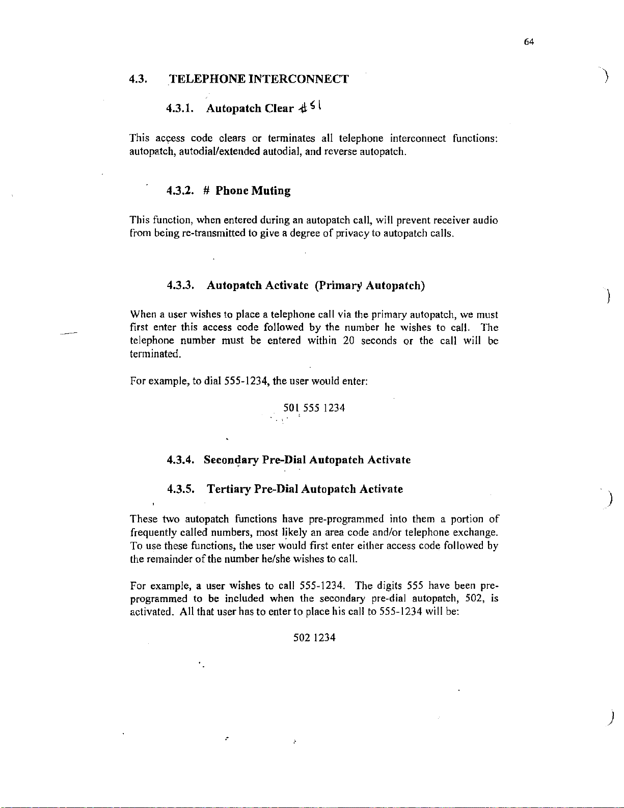
64
4.3.
This
autopatch, autodial/extended autodial, and reverse autopatch.
TELEPHONE INTERCONNECT
4.3.1. Autopatch Clear
ac~ess
code clears or terminates all telephone interconnect functions:
.'.(\;
~
l
4.3.2. # Phone Muting
This function, when entered during an autopatch call, will prevent receiver audio
of
from being re-transmitted to give a degree
privacy to auto patch calls.
4.3.3. Autopatch Activate (Primary Autopatch)
When a user wishes
first enter this access code followed by the number
telephone number must be entered within
terminated.
to
place a telephone call via the primary autopatch,
he
wishes to call. The
20
seconds
or
the call will
we
must
be
)
)
For example, to dial 555-1234, the user would enter:
501
555 1234
4.3.4. Seconclary Pre-Dial Autopatch Activate
4.3.5. Tertiary
These two autopatch functions have pre-programmed into them a portion
frequently called numbers, most likely an area code and/or telephone exchange.
To use these functions, the user would first enter either access code followed
the remainder
For example, a user wishes to call 555-1234. The digits
programmed
activated. All that user has to enter to place his call
of
the number he/she wishes to call.
to
be included when the secondary pre-dial autopatch, 502,
Pre-Dial Autopatch Activate
to
555-1234 will
502 1234
555
have been pre-
be:
of
by
)
is
.·
)

65
'
l
4.3.6. Redial
This function activates the autopatch and automatically dials the last telephone
number called.
4.3.7. Autodial/Extended Autodial Procedure
Emergency telephone numbers or individual user telephone numbers have been
programmed into a 3 digit code.
emergency services or his/her own telephone number
digit code and the
qialing will begin.
All that the user needs to
do
to call one
is
to enter the assigned 3
of
the
4.3.8. Reverse Autopatch
)
Reverse autopatch gives access to the repeater from the telephone network
answering incoming calls
contacting other repeater users or for activating functions. To contact another
repeater user, he use the Reverse Autopatch Alert access code described below.
To activate functions, the user must first dial the repeater phone, wait for the
tone burst, and then enter the desired function access code.
on
the autopatch telephone line for the purpose
by
of
4.3.9. Reverse Autopatch Alert
When placing a call via the repeater telephone, the repeater phone number must
first be dialed. After
autopatch alert access code,
The repeater will send out
)
has been placed and he should enter the autopatch activate code, 501, to
complete the connection.
"the
Mark 4 answers, the user must enter the reverse
505,
if
he wishes to contact another repeater user.
an
alert signal. This will inform a listener that a call
)

66
4.4.
The
Clear codes are not used with
This code will disable phone muting that was enabled
this code erases the access code buffer in the event that
entering an access code.
Normally DTMF tones are muted (not re-transmitted). This code causes the
tones to be unmutes so the Mark 4
They may now be re-transmitted to control equipment not associated with the
Mark 4. For example,
OTHER
USE_R
FUNCTIONS
4.4.1. User Function
cod~
is
used to clear all user functions with an' access code
4.4.2. * Unmute/Buffer
4.4.3.
**
Ignore Access
**
125
Clear
User mailboxes.
.jl'
[;O
of
520 or higher.
Clear
by
the "#''.
an
error was made when
will ignore the DTMF digits following the
would pass transparently through the repeater.
In
addition,
••.
4.4.4.
Tl1is
code will reset the transmission time-out timer
caused a time-out.
access, this code will awaken the repeater for normal communications. Other
functions may be activated without first entering the Wakeup code. For
example, the autopatch may be activated
code.
Timer
Reset
·When the repeater
Or
Wakeup
is
by
operating
entering
in
the event that a user has
in
the Wakeup mode
just
the autopatch activate
of
4.4.5. Sleep
This code will put the repeater to sleep when
and has been awakened. When this code
will cease and no tail is sent.
it
is
operating
is
entered, the transmitter operation
in
the Wakeup mode
4.4.6. Play Information (Bulletin) Message
This code will allow repeater listeners to access pre-programmed information.
)
)

4.4.
7.
Clock Time Announcement (MF)
67
By entering this code, users may obtain a readout
User function 509 gives a greeting followed
voice.
For
voice.
example: "Good morning, the time
of
is
8:05am."
clock time
by
the time
in
a female
in
a female
4.4.8. Analog To Digital Converter Readouts (MF)
510 Gives value
511
Gives value
512 Gives value
513 Gives value
514 Gives value
The above functions may be used to obtain a remote reading
temperature, or any other external analog sensors. For example, entering 512
might produce a tail message
"Repeater power
85
is
and
the scaled reading
in
watts"
of
analog to digital convertor I
of
analog to digital convertor 2
of
analog to digital convertor 3
of
analog to digital convertor 4
of
analog to digital convertor 5
of
voltage, current,
of
"Repeater power
is
the message programmed by the control operator
of
analog/digital convertor 3.
in
watts 85". The message
4.4.9. Pulse Outputs
Two types
either by themselves or
the pulse outputs
pulse to be output for the entire time which the *
of
pulse outputs are available for controlling external equipment
in
combination with other user function outputs. One
is
activated by entering
a*
(single DTMF entry) and causes a
is
present.
of
by
Any user function output may also be pulsed
access code followed by the digit
7,
function output
)
1,
that is, 5251. This will cause a fixed length
entering the access code followed by the digit
codes are entered
clear code to release the function.
Since pulsing causes the function outputs to be turned on and then off, the pulse
access codes may also be used to clear individual user function outputs. For
example, assume that both user functions 3 and 6 have been activated
sequentially entering access codes
function output 6 while keeping function output 3 active. We can achieve this
result by entering the pulse access code for function
send a pulse on function output 6 but since the function
pulse will not lie noticed. However, at the end
output 6 will be turned
enter the user function access code 525 followed
in
this manner
off
to end the pulse and will remain off.
l.
For example, to generate a pulse
t.o
cause pulses, it
523
and 526.
entering the user function
by
of
pulse
in
a similar manner by
1.
When user function access
is
not necessary to enter a
Now
assume we wish to clear
6,
5261. This will try to
is
already turned on, the
of
the pulse period, function
on
user
the digit
by
)

4.4.10. Serial Output
68
Certain external equipment
rather than single output pulses. For example, some digital transceivers can be
controlled by accumulating pulse streams
exact control nature varies with the type
of
format
this type.
The serial output function
user function output
code are outputted as pulses
code
the user function
pulses will be outputted
stays active until cleared.
the Mark 4 serial output can be a powerful means to perform control
1 I to be activated. Any digits entered following the access
5153
is
entered, then user function I I
12
output.
is
more easily controlled with sequential pulses
in
a.
shift register or counter. The
of
transceiver, but the generalized
is
activated by entering access code 515. This causes
on
user function
If
the digit 7
on
user function output
12
output. For example,
is
activated
is
then entered,
and
12.
User function output I I
if
three pulses occur
an
additional seven
of
access
on
4.4.11. Echo Function (Mm)
The Echo function allows repeater users to record and playback a sample
as
own speech
entering access code 516 and immediately speaking any message (do not remove
carrier after entering the access code). A spoken message
duration may
that it has stored the message by sending a short tone burst. To play the
message, briefly key the repeater and the message will be echoed on the repeater
tail. Test messages recorded using the Echo function are automatically erased
after being played.
a means to check their audio quality. The function
up
be
stored. At the end
of
the transmission, the Mark 4 will indicate
to 30 seconds
of
is
used by
their
in
)
)
4.4.12. Readout
Of
Received Signal Deviation, Signal Strength, And
Frequency Offset (MF)
This function allows repeater users to get a readout
the repeater. The readout
receiver. The function will stay active until it
first enter the access code, 520, and release the PTT button. A readout will
heard but should be disregarded. Next, key the repeater and speak for a
MINIMUM OF 5 SECONDS. Release the PTT button and the repeater will
respond with'a readout
transmission. The deviation reading will be the peak deviation which occurs
during the first five seconds
is
only given when accessed from the repeater
of
your signal. The readout will occur
of
the transmission.
of
their signal as heard
is
cleared. To obtain the readout,
on
the tail
of
by
be
the
)

69
Signal report messages are
one
frequency
the first five seconds
(readouts range from
frequency.
Several users may check their -deviation, strength, and frequency while the
function
each readout.
kilohertz low." This readout means that the peak deviation during
is
still active. In this case, the access code,
of
the form: "Check four point five kilohertz, S nine,
of
transmission was
SI
to over S9) and the received signal was I kilohertz
4.5
kilohertz, the signal
520,
is
need not be entered for
very strong
off
4.4.13. User Function Outputs
Twelve independent logic outputs are provided which may be individually
activated by user function access codes for
as directional antennas.
521
)
User Function I Output Activate
User Function 2
522
User Function 3 Output Activate
523
524
User Function 4 Output Activate
525
User Function 5 Output Activate
User Function 6
526
527
User Function 7 Output Activate
User Function 8
528
529
User Function 9 Output Activate
User Function I 0 Output Activate
530
User Function
531
532
User Function
controlling external equipment, such
Output Activate
Output Activate
Output Activate
11
Output Activate
12
Output Activate
Any individual output can be turned
followed by I. For example, clear User Function
off
by entering the function number
I:
5211
)
4.4.14. Link Functions
533
Link Function I Activate
534
Link Function 2 Activate
User functions are provided for linking
When either
sent
on
these messages-if a control operator has programmed
is
active, other functions may be activated.
of
these functions are active, a message designated
the repeater tail. Cross-connections between links can
to
equipment on other frequencies.
LK
I or LK2
be
done through
it
to
do so. When the link
is

! \ ' -.·''
~··
4.4.15. Tone Pad Tests
70
Once the function has been activated
io
tests
all rows and columns (not including
digit can be found with this test. The 7 access codes are
THE
WHILE THE 4TH IS ENTERED
The test
then pausing to listen for the repeater tail.
111essage
checked. Additional test flexibility
"OK" message
DTMF digit (e.g.
check DTMF levels may be used individually or
123, 456, 789,
FIRST 3 ACCESS CODES ARE ENTERED FROM LEFT TO RIGHT
is
done
by
entering any one
"OK"
in
CW
or voice will be sent and the next row or column many be
is
sent
in
response to any entry of#O followed
#05). This may be useful
by
entering the access code, 535, seven
in
colu111n
#0*'
FROM RIGHT TO LEFT.
of
is
4)
of
the tone pad. A single faulty
as
14
7,
258, 369
the access codes, for example 456, and
If
the access code
possible with the row 4 test because the
in
certain applications.
combination
follows: ·
is
accepted, the
by
any other single
to
test
4.4.16. BCD Control Output
This feature enables the Mark 4 to load external shift registers so the shift
in
registers can be used to control other equipment
provides both data and clock pulses to the shift registers so
needed to obtain a BCD output format. .
BCD format. The Mark 4
no
other circuitry
)
is
This feature
the BCD digits which are to be outputted
For example,
following access code would be
This example uses to BCD digits (2 and 4). The feature may be used with any
number
Data pulses from the Mark 4 are output on rear panel terminal 29
clock pulses are output on rear panel terminal
high data rate so
external shift registers. ·
is
activated
if
it
of
BCD digits lo a maximum
short leads should be used to connect
by
entering User Function access code 536 followed by
is
desired to output the digits 2 and 4
followed
e~tered:
53624*
often
digits.
30
(UFl2).
by
the character.
in
BCD format then the
Pulses are output at a
from
(UFI I) and
the Mark 4 to the
)
)

71
)
Pulses are output in a format which can directly load a 74LS164, or equivalent,
to
+5
shift register. Pullup resistors (4.7 Kohms
TB30. Shift register pins
and
volts and pin 7 should be connected to ground. BCD output digits are available
on
the shift register pins as follows:
First
Digit on Pins
MSB LSB
10
11
12
13
Each shift register has outputs for two BCD digits.
to
are
digits are desired then two shift registers are
entering an access code
3 and 4 would be contained
be used then shift registers may be cascaded. For example,
of
Where BCD digits I and 2 would be contained
4.4.17. BCD Serial
I,
9 and
the form:
5361234*
in
the second shift registers.
14
Output
volts) should be used on TB29
should be connected directly
Second Digit on
MSB
3 4 5 6
If
more than two BCD digits
if
four BCD
used,
and the digits are created by
in
the first shift register and digits
Function
to
Pins
LSB
+5
User Access Code: 536 followed by
536WXYZ where
if
example,
Function outputs clock and serial data on rear panel terminal strip:
)
Data.output
on
the rising edge
signals for suffix value Y=3 are
user enters 5361234 then w =
TB29=data
w,
x, y and
in
a 4-bit BCD code for each access code suffix digit. Data
of
the clock. Data
z,
as
up
to
four digits. That is, user may enter:
represent digits
1,
is
sent with LSB first. For example, output
follows:
in
the range zero
x = 2, y = 3, and z =
TB30
=clock
4.
to
nine. For
is
valid

Circuitry for converting four BCD digits to parallel format
72
.,
/ / /
.,
LSB
-
' '
7
+5
1,9,14
8
74LS164
2 2
13
12
DigitW
11
IO
6 5 4
Digit x
3
MSB
/ / /
13 12
LSB
DigitY
7
74LS164
11
IO
+5
-
1,9,14
TB30
8
TB29
6
5 4
DigitZ
3
MSB
\
..
__
'.__,
·--_.,--
._,.

73
I
'
The
used to activate
a suffix digit in
the
Assume that user
access code
present time but
record a mailbox message for user
record access code,
)
immediately after entering the access code.
entire message is spoken.)
Master. When I finish speaking the message, the Mark 4 will indicate that it has
successfully recorded the message
by sending a short
4.4.18. User Mailboxes (MM)
extended autodial access code that has been assigned to a user will also be
the
Mailbox capability
the
range I through
repeater user who is assigned access code 600 would be:
600 Activate extended autodial
6001 Play mailbox message
6002 Record a mailbox message
6003 Erase a mailbox message
600 is a friend
600. I know that he
(have
tone
a message I wish to deliver to him. Thus, I wish to
6002, and speak the message. (Speak the message
My
burst.
of
the Message Master when followed by
3.
For example, the access codes used by
of
mine. He has told me that he
is
at work and not listening to the repeater at the
600.
To
do this, I would simply enter his
Do
not unkey the repeater until the
message would be recorded by the Message
is
assigned
Sometime later when user 600 leaves work, he can ask Message Master whether
any messages have been recorded in his mailbox by entering his playback access
code
6001.
messages have been recorded,
that it has no messages for him.
After user
erase code,
In
)
order to save memory in the Message Master for everyone, courtesy demands
that a user make his messages as short as possible and that he erase his messages
after he has listened to them.
If
any
messages have been recorded, they will be played.
the
Mark 4 will send a short tone burst to indicate
600 has listened to his messages, he may erase them by entering his
6003.
If
no
4.4.19. Voice Message Lists
This feature allows callsigns to be announced for all repeater users for whom
Message Master messages have been recorded. Any repeater user may cause the
callsigns to be sent on the repeater tail by entering the access code 517.
For example,
600 (by entering the access code 6002 and speaking the message) and a repeater
user then entered the access code 517, the
WlXYZ."
if
a Message Master message had been recorded for repeater user
Mark· 4 would send "Message for
}

For callsigns to be announced using this feature, the callsigns must be
programmed into the Mark 4 using the
"Enter ID" mode as described above.
74
The callsign list may
example, the callsign list may be included
Message:
would enter the access code:
where,
934
098 000 tells the Mark 4 to send the callsign list as part
To
include the call sign list in the periodic message, a control operator
is
the command to program the periodic message,
also be sent
as
098 000 #
934
part
of
other messages
in
the Periodic Announcement
of
if
the message, and
desired. For
# indicates that all information has been entered.
The characters
send the callsign
message such as an ID or Tail Message.
Callsign lists may also be included
098 000). For example, the periodic message could be programmed to give the
callsign list by entering the command:
098 000 when included
list
Thus, the callsign list can be sent
in
the text
in
messages by using 098
934
098
001
#
o"f
a message tell the Mark 4 to
in
any programmable
001
(rather than
)
When 098
be sent when there are no messages for users.
001
is
used rather than 098 000, the message "NO MESSAGES" will
.·
)
)

75
)
Individual and group call two-tone sequential paging signals can be generated by the Mark 4
response to DTMF access codes. Access codes
paging signals, and access codes
Paging signals are sent on the repeater tail after an access code
Motorola Group 2 tones are the standard tone frequencies furnished
frequencies corresponding to DTMF digits entered are as follows:
DTMF
)
4.5.
Digit
Entered
0 569.l 120
l 600.9
2 634.5
3
4 707.3 124
SEQUENTIAL
5 746.8
6 788.5
7 832.5 127
8
9
TONES
in
the range 200 to 299 originate individual unit
in
the range 20# to 29# originate
Tone
Frequency
in
Hz
669.9
879.0
928.l 129
in
group call paging signals.
is
entered by a repeater user.
in
the Mark 4. Tone
Motorola
Number
Reed
121
122
123
125
126
128
in
To send
to the tone frequencies to be sent. Enter the sequential tone access code leading digit (factory
programmed as the digit 2) followed by the DTMF digits corresponding
frequencies.
)
EXAMPLE:
832.5 Hz enter access code:
Individual unit pages are sent with the first tone having a duration
digit having a duration
To send a group call
Enter the sequential tone access code leading digit (factory programmed as the digit 2) followed
by the DTMF digit corresponding to the tone frequency to
an
individual unit paging tone select DTMF digits from the above list which correspond
to
the paging tone
·
,To
Where,
send an individual unit page consisting
207
2 is the leading digit for sequential tone functions
0 is the DTMF digit corresponding to 569. l Hz
7 is the DTMF digit corresponding to 832.5 Hz
of
three seconds.
or
all-call paging tone, select desired tone frequency from the above list.
of
tone frequency
of
be
sent followed by the # character.
569.l
Hz followed by
one second and the second

76
EXAMPLE: To send a group call paging tone
Where,
is
the leading digit for sequential tone functions
2
J is the DTMF digit corresponding to 669.9 Hz
# indicates group call page.
Group call and all-call pages consist
9490 Sequential tone feature disabled
9491
Sequential tone feature enabled
of
of
669.9 Hz enter the access code: 23#
a single tone having a duration
of
8 seconds.
)
)
)

·-
MARK
Speaker
Repeater
@
4CR
REPEATER
Control
Repeater
@
1.
"'"
-
D.C.MICRO.'<MPERS
-
-
STATUS
······-12.
REC
Power
AP
INDICATORS -
TTS
CMD
MIC
FUNC.
XMIT
•
CTCSS
XMIT
ON
@
2.
"'"
,
I
DISC
DEV~PA
SIG""'"'-
10.
.~
.o
Li'
I//.,,."
MllllAMPERES
MONITOR
11.
.e
~
EXE
-
RF
3.
4.
FIGURE
5.
1:
FRONT
6.
PANEL
7.
8. 9.

)
)
)
/
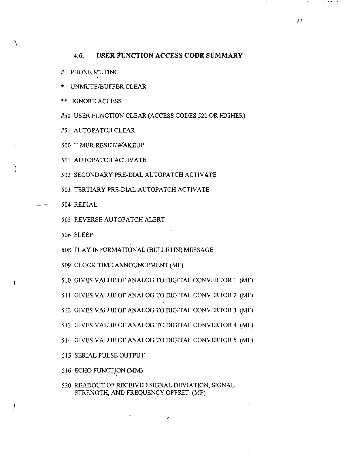
)
4.6. USER FUNCTION ACCESS CODE SUMMARY
# PHONE MUTING
* UNMUTE/BUFFER CLEAR
**
IGNORE ACCESS
USER FUNCTION CLEAR (ACCESS CODES 520 OR HIGHER)
#50
#51
AUTOPATCHCLEAR
TIMER RESET/WAKEUP
500
501
AUTOPATCHACTIVATE
502 SECONDARY
PRE-DIAL AUTOPATCH ACTIV8TE
77
503
TERTIARY PRE-DIAL AUTOPATCH ACTIVATE
504 REDIAL
505 REVERSE AUTOPATCH ALERT
506 SLEEP
508 PLAY INFORMATIONAL (BULLETIN) MESSAGE
509 CLOCK
510 GIVES VALUE OF ANALOG TO DIGIT AL CONVERTOR I (MF)
511
GIVES VALUE OF ANALOG
512
GIVES VALUE OF ANALOG TO DIGITAL CONVERTORJ (MF)
513
GIVES VALUE OF ANALOG TO DIGITAL CONVER TOR 4 (MF)
514
GIVES VALUE OF ANALOG TO DIGITAL CONVERTOR 5 (MF)
515
SERIAL PULSE OUTPUT
TIME ANNOUNCEMENT (MF)
TO
DIGITAL CONVERTOR2 (MF)
5 l 6 ECHO FUNCTJON (MM)
520 READOUT OF RECEIVED SIGNAL DEVIATION, SIGNAL
STRENGTH, AND FREQUENCY OFFSET (MF)
)
.-

521
USER FUNCTION I OUTPUT ACTIVATE
522
USER FUNCTION 2 OUTPUT ACTIVATE
523
USER FUNCTION 3 OUTPUT ACTIVATE
USER FUNCTION 4 OUTPUT ACTIVATE
524
525
USER FUNCTION 5 OUTPUT ACTIVATE
526
USER FUNCTION 6 OUTPUT ACTIVATE
USER FUNCTION 7 OUTPUT ACTIVATE
527
USER FUNCTION 8 OUTPUT ACTIVATE
528
529
USER FUNCTION 9 OUTPUT ACTIVATE
530 USER FUNCTION I 0 OUTPUT ACTIVATE
78
)
531
USER FUNCTION
USER FUNCTION
532
533
LINK I FUNCTION ACTIVATE
534 LINK 2
535
TONEPAD TEST FUNCTION ACTIVATE
FUNCTION ACTIVATE
11
OUTPUT ACTIVATE
12
OUTPUT ACTIVATE
.l
.·
)

79
)
·s.
··,.FRONT
. "·"'
The Mark 4 repeater front panel includes the following controls and indicators:
!.
2.
3.
5.1 •
Power/Squelch - Controls
squelch threshold. Does not control DC power input to the repeater so repeaters operating
from DC power only, and repeaters using automatic transfer to emergency DC power sources
will continue to operate even when the
Volume - Controls local front panel speaker volume. Does not affect re-transmitted audio
level. When leaving the repeater unattended,
minimum (fully counter-clockwise)
Speaker
switch
repeater <up> position). In the repeater position, the speaker monitors telephone' line audio
and messages generated by the Mark 4
. receiver.
Switch - Allows the front panel speaker to monitor receiver output audio (with the
in
PANEL······
FRONT
' - ! '
5.1.1. l\<lark 4
the local <down> position), or transmitter input audio (with the switch
PANEL
Repeater
AC
.,
!
-·
Front
power input (on/oft) to the repeater and sets the receiver
AC
as
a courtesy to other users
' '
,.-.
Panel
power source
it
is good practice to set the speaker volume to
as
well
as
is
switched off.
of
the repeater site.
re-transmitted audio from the repeater
in
the
4.
Control
operation. In the local <down> position, the receiver signal present
so the Mark 4 will not respond
be operated from the local microphone
XHLD, are not disabled when operating
used when performing tests at the repeater site.
5.
Power
not indicate whether DC power
6..
Microphone
.
inputs from the local microphone. Jack pin assignments are shown on the wiring drawings
the Appendix.
7.
Transmit
8.
Transmit
Switch - The repeater <up> position
to
received signals. The local position allows the Mark 4
as
a remote base station. Control inputs, such
in
Lamp
- This lamp indicates that
is
'
Jack
- This 4-pin jack accepts audio, push-to-talk control, and DTMF tone
Lamp
Switch - This switch disables
-This
lamp indicates that the transmitter
applied to the unit.
AC
of
this switch allows normal repeater
the local position
power
is
applied to the Mark
is
active
(COS) output
so
this position may also be
4.
The lamp does
.·-.
" .
9.
Meter
function meter.
Discriminator
10.
Switch - This switch selects the measurement value to be displayed by the multi-
· , . "
Meter
- Indicates the frequency offset error
of
received signals. The meter
a zero-center meter so on-frequency received signals will cause the meter to display a center
scale reading. The meter will indicate left
of
center for signals which are low
in
is
disabled
to
as
frequency,
in
is

80
and right
given
11.
Multi-Function
of
center for signals which are high in frequency. Meter calibration information is
in
the Receiver section
Meter
of
this manual.
- This meter can display received signal strength, received signal
peak deviation, transmitter exciter current, transmitter power amplifier current, and
transmitter relative power output. The meter display is controlled by the Meter Switch.
Meter calibration information
manual.
12.
Status
Lamps
- Six status lamps provide the following indications:
.,
'
is
given
in
the Receiver and Transmitter sections
I - Received signal present
2 - Autopatch telephone interface active
3 - DTMF tone present
4 - Command signal present
·
,,
. · 5 - Any user function output active ·
6 - CTCSS tone present
5.1.2.
Mark
4C Controller
Front
Panel
The Mark 4C controller front panel include,s the following controls and indicators:
Power
I.
so controllers operating from
transfer to emergency DC power sources,
Switch - Switches
AC
power to the controller. Does not control
DC
power only, and controllers operating with automatic
will· continue to operate when
DC
power to the unit
AC
power is
switched off.
of
)
this
)
2. Volume - Controls the local speaker audio level. Does not affect re-transmitted audio level.
3.
Power
Lamp
- Indicates that AC power
is
applied to the unit. Does not indicate whether DC
power is applied to the controller.
4.
Transmi~
Microphone
5.
from the local microphone. Jack pin assignments are
Lamp
Jack
- Indicates that the transmitter
is
on. )
- This 4-pin jack accepts audio, push-to-talk control, and DTMF tones
show11
on the wiring drawings
in
Appendix.
6.
Status
Lamps
- Six status lamps provide the following indications:
I - Received signal present
2 - Autopatch telephone interface active
·1:
3 - DTMF tone present
· 4 - Command signal present
:·:,
..
,, 5 -Any
user function output
6 - CTCSS tone present
1:.
active'''"
::·
·,
i'
'''
.
..
:
..
i
' .
;-
..
,,;
th;:
)

5.2. REAR PANEL
The Mark 4 rear panel contains the following:
81
)
4 15-terminal barrier strips (terminals TB 1 to
9 RCA type audio jacks
3 Ampere AC power fuse
(5 A
on
5 Ampere DC power fuse
Coaxial transmitter output
Coaxial receiver input
jack
Mark 4C Controller)
jack
(Mark 4 repeater only)
(Mark 4 repeater only)
TB60)
5.2.1. TERMINAL DESIGNATIONS
TB! Ground
TB2
ADI
TB3 AD2
TB4 AD3
TBS AD4
TB6 AD5
TB7
PULS
TBS EXT!D
TB9 CFl-(Remote squelch adj.
10
TB
TB!l.
TB.12
TBI3
TB14 CF6
TBl5
)
TBl6
TBl7
TB18 BZ
TBl9
TB20 UF2
TB21 UF3
TB22 UF4
TB23 UF5
TB24 UF6
TB25 UF7
TB26 UF8
TB27
TB28 UFIO
TB29 UFJ l
TB30 UF12
TB3l
CF2 Mark 4 rpt. only)
CF3
CF4 .
CFS
CF7
Ground
AB
UFI
~F9
Ground
TB32-TB39
TB40
TB41
TB42
TB43
TB44
TB45
TB46
TB47
TB48
TB49
TB50
TB51
TB52
TB53
TB54
TB5S
TB56
TB57
TB58
TB59
TB60
RV
option
cos
SEQT
COSL
XHLD
CMD
vox
Ground
+5V pullup
Limiter
Discriminator
Deviation
K3
relay
K2
relay
Kl
relay
PTT
pullup
+5V
no connection
Phone line
Phone line
Command
Command Phone
Phone
.·

82
-t·
5.2.2. Audio Jacks
Audio input/output connections are made through RCA-style rear panel mounted jacks. Because
be
low
in
audio connections may
be
used for all audio connections.
level and high
in
impedance, it
·1
is
suggested that shielded cable
)
5.2.3.
A secondary repeater receiver may be connected to this input.
receiver audio will
accepted from the secondary receiver only
secondary receiver
repeater receiver. The audio level applied to this input should be adjusted to
No internal level adjustment
5.2.4.
Audio from an external command receiver may be applied to this input. The applied audio level
should be adjusted to
codes to be accepted from this input, a received-signal-present
receiver must
only to the DTMF decoder and not to the repeater transmitter.
be
5.2.5.
Audio from a link receiver may be applied to this input. The applied audio level should be
nominally
the audio circuit board.
0.5 to 1.0 volts peak-peak and may be precisely adjusted using potentiometer
JAl
(RX2)
If
this input
be
directly mixed with the primary receiver audio. Access codes will
if
a received-signal-present (COS) signal from the
is
connected to rear panel terminal TB40
is
provided.
JA2
(CMD
0.5 volts peak-peak (no internal level adjustment
connected to rear panel terminal TB44. Audio applied to this input
JA3
_(LINK
IN)
IN)
in
the same manner as the primary
(COS) output from the command
is
used, the secondary
0.5 volts peak-peak.
is
provided). For access
is
RI
be
routed
16
on
)
5.2.6.
This output may be used to drive a link transmitter. The audio output level
peak-peak.
5.2.7.
This spare audio input may be used to connect external audio sources to the repeater transmitter.
Audio applied to this input should be externally adjusted to a nominal level
JA4
JA5
(LINK
OUT)
is
nominally I volt
of
1 volt peak-peak.
)
83
\
'
Transmitter audio is available at this output. In Mark 4 repeaters, the use
optional;
transmitter. The audio level available at this output is adjusted by potentiometer R88 on the
audio circuit board to a level
5.2.8. JA6
of
this output
in
Mark 4C controllers, this output provides audio drive for the external repeater
of
I volt peak-peak.
is
5.2.9. JA7
This spare audio input may be used to connect external audio sources to the repeater transmitter.
of
Audio applied to this input should be externally adjusted to a nominal level
5.2.10.
In
Mark 4 repeaters without the Receiver Voting option, this output may be used to monitor
repeater receiver audio.
used to monitor voted receiver audio. In Mark 4C controllers, this
from the external primary repeater receiver should be applied to this input at a nominal level
volt peak-peak. Potentiometer R22 on the backplane circuit board may be used to compensate
for variations
in
receiver output from this nominal level.
JAB
In
Mark 4 repeater with the Receiver Voting option, this output may be
jack
I volt peak-peak
is
an
input and audio
of
..
I
5.2.11. Terminal Descriptions
Unless otherwise specified, all outputs are driven by active low, open collector gates capable
withstanding +25VDC
Active low means that when the output
and pull the load voltage to ground (to less than 0.5 volts). Open collector means that the output
is
in
a high impedance condition when the output is not selected. This
arrangement because it permits
circuitry may be connected directly
should be included
)
requires high power control (greater than 25 volts, 25mA) then
Figure 2 on
function output.
Unless otherwise specified, all logic inputs are high impedance (4700 Ohm) and should be
driven from
OV
minimum, 0.8V maximum). Damage may result
Jess
than 0 volts.
To minimize noise pickup and radiation it
signal and ground wires, be used for all connections to rear panel terminals (except telephone
connections). A ground terminal
purpose. Telephone
Page
TTL
in
the
off
condition and capable
is
selected, it will draw current (to a maximum
"wired-or" control so manual switches or other electronic
in
parallel with Mark 4 outputs
in
the controlled equipment to guarantee turn off.
__
illustrates circuitry for driving a high power external load from a Mark 4
compatible logic levels (logic
is
provided on each
Jin~
connections are balanced circuits and do not need a ground connection.
I=
is
recommended that twisted pair wiring, consisting
of
sinking 25mA
if
lfthe
an
external relay should be used.
3.5V minimum, 5.5V maximum; logic 0 =
if
inputs are driven greater than +5 volts or
of
the rear panel terminal strips for this
in
the on condition.
is
an
especially flexible
desired. A pullup resistor
controlled equipment
of25mA)
of
of
)

S.2.12. TB2-TB6 (ADI-ADS)
84
These inputs allow five independent analog voltages
the Mark 4 and reported by voice messages. Applying voltages outside this range may cause
permanent damage. These inputs are available only when the MF option
in
the range 0 to 5 volts to be measured by
is
installed.
S.2.13. TB7 (PULS)
This active low output
as
long
as
the *
is
This active high output presents a momentary
is
required
if
the Mark 4 has been commanded to use external identification.
present.
S.2.14.
is
energized whenever a DTMF
TBS
(EXTID)
pulse(>
*tone
I 00 usec) whenever callsign identification
is
entered. The output remains low
S.2.lS. TB9 -TBS (CF1-CF7)
Active low command function outputs. On Mark 4 repeaters, TB9
of
remote control
condition and the front panel squelch control has
is
controlled
repeater squelch. When CFI
by
the front
pan~!
squelch control.
is
OFF, the squelch
no
effect. When CFI
(CFI)
is
pre-wired
is
held
in
the
is
ON, the squelch setting
to
full
allow
tight
)
S.2.16. TB17 (AB)
A low (ground) logic level applied to this input signals the Mark 4 that the autopatch phone line
is
already
share a single autopatch phone line
together.
message
repeater.
in
use and not available for initiating a telephone call. Several Mark 4 repeaters may
if
terminals TB I 7 and TB I 8 on all repeaters are connected
If
connections are made in this manner, then repeater users will be given a line-busy
if
they attempt to initiate a call when the phone line
is
already being used
by
another
S.2.17. TB18 (BZ)
This output
be used to allow several Mark 4 repeaters to share a single autopatch phone line (see
description).
is
pulled
to-
ground whenever the autopatch telephone line
is
in
use. The output may
TB
17
)
)

85
)
Active low user function outputs. Each output
normally OFF (open collector) and
is
code
25mA
entered. The output buffers can withstand 24 VDC
in
the ON condition.
5.2.18. TB19 - TB30 (UF1-UF12)
is
driven
is
turned ON (pulled to ground when the associated access
by
an open-collector driver which
in
the OFF condition and can sink
is
5.2.19. TB32 - TB39
These terminals are used with the Receiver Voting option.
5.2.20. TB40 (COS)
)
In
Mark 4 repeaters, this terminal may be used as
of
a low power active high output capable
high whenever a received signal opens the receiver squelch.
In
Mark 4C controllers, this terminal
of
indicating the presence
If
input.
Mark 4 processor circuit board should be moved so that it connects from terminal
adjacent
the repeater receiver provides only
+5
volt terminal.
received signal should
driving one equivalent TTL load. The output
is
an
output for monitoring receiver activity.
an input. An active high TTL compatible signal
be
connected from the repeater receiver
an
active low COS output, then
jumper
It
is
is
driven
to
this
E 1 on the
El
to
the
5.2.21. TB41 (SEQT)
On
units equipped to generate two-tone sequential paging signals, the sequential audio tones are
available at this output. Connections to transmitter audio circuits are made within the Mark 4 so
is
this output
impedance circuitry.
intended primarily for monitoring.
It
may also be used to drive external high
5.2.22. TB42 (COSL)
An active high TTL compatible signal may be applied to this input from an external link receiver
of
to indicate the presence
link receiver provides only an active low
circuit board should be moved so that it connects from terminal E2
terminal.
received signal on a linked system connected to the Mark
COS output then jumper E2 on the Mark 4 processor
to
the adjacent +5 volt
4.
If
the
)
.-

5.2.23. TB43 . (XHLD)
Any external equipment needing to keep the repeater transmitter active,
ground (logic zero) to this input. The repeater transmitter will remain active
is
held low; therefore, external equipment which operates independently from the Mark 4 should
be equipped with its own time limit circuitry to insure that the transmitter
removing the ground from this input).
m~y
do
as
so by applying a
long
as
this input
is
deactivated (by
86
External equipment which
time limits to deactivate
diodes from Mark 4 function outputs. As
would be used to hold the repeater transmitter active whenever user function outputs 5 or 7 are
active. The two user function outputs control separate external equipment, but both function
outputs are connected through isolating diodes to TB43 so the transmitter will be held active
when either user function
With this arrangement, Mark 4 function time limits determine how long the repeater transmitter
will remain active so no external timer
outputs may be connected in this manner.
is
controlled by Mark 4 function outputs may rely on Mark 4 function
the
transmitter
is
active.
if
connections are made to this input through isolating
an
example, figure 3 shows the connections which
is
necessary. Any number
of
user or command function
5.2.24. TB44 (CMD)
An
active high
receiver may be applied to this input to cause the Mark 4 to accept DTMF commands from the
command receiver. The input signal may be obtained from the command receiver squelch circuit
(COS) or from a CTCSS decoder connected to the command receiver.
provides only
the Mark 4 processor circuit board should be moved to connect from terminal
+5
volt terminal.
TTL
compatible signal indicating the presence
an
active low signal to indicate the presence
of
signal from a command
If
the command receiver
of
received signal, the jumper
E3
to the adjacent
E3
on
5.2.25. TB45 (VOX)
In
applications using voice control, this terminal may be used as either
Circuitry with the Mark 4 causes the terminal to be pulled to ground (logic zero) whenever
modulation exists on a signal present at the repeater receiver. The presence
be
modulation may
operation may apply a ground to this terminal to indicate to the Mark 4 that a tone burst has been
received.
monitored by using this terminal
as
an
output. Applications using tone burst
an
input or
an
of
received signal
output.
5.2.26. TB48 (Received Signal Strength)
In
Mark 4 repeaters this high impedance output delivers
volts which is proportional to received signal strength.
MF
option, a voltage
will translate the applied voltage to a signal strength value for remote readout.
in
the
range 0 to
+5
volts may be applied to this terminal. The Mark 4C
an
analog voltage
In
Mark 4C controllers equipped with the
in
the range 0 to 5
)
)

87
\
In
Mark 4 repeaters, this high impedance output delivers
to
received signal frequency error. A voltage
frequency signal.
to +2 volts may be applied to this terminal. The Mark 4C will translate this applied voltage to a
frequency offset value for remote readout.
5.2.27. TB49 (Receiver Discriminator)
an
analog voltage which
of
approximately +I volt corresponds to
In
Mark 4C controllers equipped with the MF option, a voltage
is
proportional
in
the range 0
an
on
5.2.28. TB50 (Received Signal Deviation)
In
Mark 4 repeaters this high impedance output delivers
to received signal peak deviation. In Mark 4C controllers equipped with the MF option
analog voltage in the range 0 to +5 volts may be applied to this terminal. The Mark 4C will
translate the applied voltage to a peak deviation value for remote readout.
an
analog voltage which
is
proportional
an
)
5.2.29.
An optional relay, K3, may be provided for external equipment needing high power control.
Custom connections are used when
applications.
IfK3
TBSl
is
not provided, then
(K3
Relay)
K3
is
provided to meet special customer needs for specific
no
connection is made to this terminal.
5.2.30. TB52 (K2 Relay) ·
This output provides for
link transmitter
accordance with backplane circuit board wire jumpers
is
Output Voltage
5.2.31. TB53
This terminal provides a voltage (or ground) output through a relay contact whenever the
repeater transmitter
control the repeater transmitter. In Mark 4 repeaters, transmitter control
switching and no connection to this terminal
provided
in
accordance with backplane circuit board wire jumpers as follows:
cont~ol
to be activated, and a voltage (or ground)
Ground
+5 Volts
+!2
Volts
is
to be activated.
of
an
external link transmitter. Relay K2
as
follows:
Backplane Jumper Installed
W5
W6
W4
(Kl
Relay)
In
Mark 4C controllers this output should be used to
is
necessary. The voltage applied to this terminal
is
energized then the
is
provided at this terminal
is
done with transistor
in
is
)

88
Output Voltage
Ground
+5
Volts
+l2Volts
Backplane Jumper Installed
WS
W9
W7
5.2.32. TB54 (PTT)
This terminal
depressed. Alternatively, the terminal may be pulled to ground to cause the repeater transmitter
to operate; however,
as
the terminal
will not be accepted from any inputs except the local microphone when this terminal
In
some situations, these characteristics may be desirable, but
(TB43)
is
pulled to ground whenever the local microphone push-to-talk switch
if
this terminal
is
held at ground (logic zero) with no timeout.
is
more suitable for keeping the transmitter active.
is
used for control, the transmitter will remain active as long
In
addition, DTMF access codes
is
held low.
in
most cases, the XHLD input
is
5.2.33. TB57 - TB58 (Phone Line)
- )
On
units equipped with a non-registered autopatch interface, the telephone line should be
connected to these terminals. These
provided.
termi_nals
are not used when an FCC registered interface
5.2.34. TB59 - TB60 (Command Phone)
On
units equ'ipped with a non-registered optional command telephone interface, the command
telephone line should be connected to these terminals. These terminals are not used when
FCC registered command phone interface
_is
provided.
is
)
an
)

89
5.3.
The Mark 4
other mounting arrangements may be used
that access to audio and backplane circuit board adjustments
cover and access to the receiver and transmitter modules
removing the unit bottom cover.
The Mark 4 should be installed
component reliability degrades when components are subjected to temperature extremes, so
superior long-term performance can be obtained by selecting a location with moderate ambient
temperatures.
filled with electronic equipment may be subjected to high temperature caused
effect" air flow from other heat producing equipment
INITIAL
5.3.1. GENERAL
is
designed for convenient mounting
In
addition, it should be recognized that equipment mounted near the top
INSTALLATION
COMMENTS
in
a standard 19-inch equipment rack, although
if
desired. Mounting arrangements should consider
is
gained by removing the unit top
of
Mark 4 repeaters
in
a well ventilated, moisture-free location. Electronic
in
the rack.
by
"chimney
is
gained
of
by
a rack
)
5.3.2.
l.
Provide a ground connection from the Mark 4 cabinet to a good earth ground using a 16gauge or heavier wire strap. Stranded wire
upon mechanical mounting or power line connections
MARK 4 REPEATER
INSTALLATION
is
preferred for this connection. Do not rely
to provide grounding.
PROCEDURE
2.
Operate the front panel power/squelch switch to the
and connect the Mark 4 power cord to a l
access code 9161
3.
In
applications using two antennas, connect from the rear panel receiver coaxial
receiving antenna, and connect from the rear panel transmitter
or equivalent, RF power meter to the transmitting. For proper repeater operation, the
)
antennas should be positioned to achieve
concernin'g the physical antenna separation need to obtain
from the antenna manufacturer). Type RG-213/U, or equivalent, coaxial cable should be
used for antenna connections. The antennas should be tuned to the repeater operating
frequencies and should present a
In
applications where a duplexer
operating frequencies
proper repeater operation, the duplexer should provide
transmitter and receiver ports.
coaxial jacks to the appropriate duplexer terminals using RG-213/U or equivalent coaxial
cable. A Bird model 43, or equivalent, RF power meter should be inserted between the Mark
4 transmitter jack) and the duplexer
antenna).
(Command Function I ON) to allow front panel squelch adjustment.
50 Ohm resistive load.
is
used, the duplexer should be pre-tuned to the repeater
in
accordance with the instructions
Connect from the Mark 4 rear panel transmitter and receiver
20VAC, 60 Hz power source. Enter command
90dB or greater isolation loss (information
(NOT between the duplexer and the transmitting
off
(fully counter-clockwise) position
jack
jack
through a Bird model 43,
90dB isolation should
of
the duplexer manufacturer. For
90dB or greater isolation between
be
available
to the

4.
Operate the control switch to the local (down) position; then rotate the front panel
power/squelch control fully clockwise and observe that the power lamp lights. Wait
approximately
repeater transmitter, the front panel transmit lamp, and all front panel status lamps should be
off.
5.
Connect the microphone to the front panel microphone
microphone push-to-talk switch to cause the repeater transmitter to operate.
forward and reflected power readings
is
1.2:
I or lower. A VSWR greater than 1.2: I indicates a faulty or improperly tuned antenna
system (or duplexer) and continued operation under this condition may cause permanent
damage to the Mark 4 transmitter. The condition cannot be cured by adjusting the Mark 4
and must be remedied by correcting the antenna system.
6.
When the local microphone push-to-talk switch
transmit lamp will operate. When the push-to-talk switch
continue operating for approximately 5 seconds; then the transmitter will become inactive
and the lamp will extinguish.
I 0 seconds or the processor to reset. When the reset interval
jack
and momentarily depress the
on
the RF power meter and determine that the VSWR
is
depressed, the repeater transmitter and the
is
released, the transmitter will
is
complete, the
Observe the
90
)
7.
Set the speaker to the "repeater" (up) position. This allows the front panel speaker to monitor
repeater transmitter audio which includes repeated receiver audio plus autopatch and all
tones and messages generated by the Mark 4.
8.
Set the control switch to the repeater (up) position. This allows the Mark 4 to operate
response to received signals.
9.
Unsquelch the receiver by rotating the front panel squelch control
direction until receiver status lamp l lights and then adjust the front panel speaker volume
control for a comfortable listening level. With the receiver unsquelched, the transmit lamp
will light and the transmitter will operate.
I
0.
Set the receiver squelch by rotating the squelch control clockwise until the receiver status
(l)
just
lamp
lamp will remain lighted and the transmitter will remain operating for approximately 5
seconds after the squelch control
speaker during the 5 second interval.
This completes the Mark 4 repeater basic installation.
emergency power features are to used at this time, then refer to the appropriate additional
features installation sections below. When the installation
program the callsign identification and, instructions for doing this are contained
Commands section
to
set the speaker volume control to minimum. The speaker volume control does not affect re-
transmitted audio.
extinguishes. The squelch control should be left
is
set. A short courtesy tone will be heard from the local
If
linking, telephone interconnect, or
is
complete, it
of\his
manual. When the Mark 4
is
to be left unattended,
in
the counterclockwise
in
this position. Transmit
is
appropriate to
it
is
good practice
in
in
the
)
)

91
)
5.3.3.
The Mark 4C controller may be interfaced to almost any receiver and transmitter to create a
sophisticated repeater installation. However, it should be recognized that repeater service differs
from transceiver operation in that repeater service requires simultaneous transmitter and receiver
operation. Receivers and transmitters, built specifically for repeater operation, use extensive
shielding and electrical bypassing to prevent transmitter energy from degrading receiver
performance. At moderate power levels, transmitter to receiver isolation should be more than
90dB, and even greater isolation
transmitters operating
designed for continuous duty operation. For these reasons, considerable effort may be required
in
creating a repeater from transmitter and receiver units which were not originally designed for
repeater service. These issues are unrelated to Mark 4C controller operation and are outside the
scope
of
this manual. The following procedure describes the addition
a repeater which
1.
Remove any control logic and audio connections between the repeater receiver and
transmitter.
2. Provide a ground connection from the Mark 4C cabinet to a good earth ground using a I 6
gauge or heavier wire strap. Stranded wire
upon mechanical mounting or power line connections to provide grounding.
is
not being mounted
be connected between the two equipment racks or the two racks should
common point.
is
MARK4C
in
repeater service are subject to high duty cycles and are generally
assumed to be already
in
the same equipment rack
CONTROLLER INSTALLATION PROCEDURE
is
required when power amplifiers are used.
in
service.
In
addition,
of
a Mark 4C controller to
is
preferred for this connection. Do not rely
If
the Mark 4C
as
the repeater, then a ground strap should
be
grounded to a
)
jack
3. Connect from the repeater receiver audio output to Mark 4C rear panel input
Shielded cable should be used for this connection. Mark 4C receiver audio input
impedance (approx. I
source. Generally, sufficient drive
loudspeaker output terminals without introducing excessive distortion; therefore, it
recommended that audio be taken from a line output or other high level receiver output.
the repeater
4C, then audio must be taken from a point
response so the
4. Connect a TTL voltage compatible signal from the receiver carrier-operated squelch
circuit to Mark 4 rear panel terminal TB40. This signal should be
is, the receiver output should pull
input, and the receiver output should
receiver input (a pulldown resister
an open circuit output when
circumstances, should the receiver apply a positive voltage greater than 5 volts or any
negative voltage to input
see the
be made to invert the Mark 4C input.
compatible output, then see Figure I for suggested receiver circuit modifications.
is
to be used for CTCSS operation with a CTCSS decoder installed
Processor Circuit Board section
0 KOhms) and may be drive from a 0.5 volt peak-peak or greater
can NOT be obtained from receiver low impedance
in
in
the receiver which has good low frequency
CTCSS tone can be paSsed to the Mark 4C without excessive attenuation.
an
active high signal, that
TB40.
TB40 to
is
no
signal
If
the receiver provides only
+5
volts when a signal
go
to ground (0
included
is
present rather than a ) volt output). Under
of
this Manual for wiring jumper changes which may
If
the receiver does not provide a TTL voltage
'v0olts) when no signal
in
the Mark 4C
is
present at the receiver
is
present at the
so
the receiver may provide
an
active low COS output, then
JA8.
is
high
is
If
the Mark
(COS)
no
)

.~r
·-
·.
,.
~
~-
5.
Connect from the Mark 4C rear panel audio output jack JA6
4C.
input. The Mark
can deliver approximately 1.0 volts peak-to-peak at this output which
to
the repeater transmitter audio
should be sufficient to drive any transmitter high impedance input. Shielded cable should be
to
used for making this connection
6.
Connect from Mark 4C rear panel terminal TB53 to the repeater transmitter control input.
minimize noise pickup.
This Mark 4C output provides a relay contact closure to ground to activate the repeater
transmitter. Wire jumper options
+5
volts or +
section
7.
Operate the front panel power/squelch switch to the
12
volts to activate the repeater transmitter. See the Backplane Circuit Board
of
this manual for information on altering the wire jumper positions.
connect the Mark 4C power cord to a
8.
Rotate the power/squelch control fully clockwise and observe that the power lamp lights.
IO
Wait approximately
seconds for the processor to reset; during this time, the repeater
transmitter may operate. When the reset interval
in
the Mark 4C may be changed
off
(fully counterclockwise) position and
120VAC,
60
Hz power source.
is
complete, the repeater transmitter, the
if
desired to provide either
front panel transmit lamp, and all status lamps are off.
92
)
5.4. TELEPHONE INTERCONNECT INSTALLATION
Telephone loops from a customer premise
by
the telephone company to have a loss
adjusted to operate properly with such loops. Therefore, interconnect audio levels do not
nonnally require adjustment upon installation.
Board Adjustment in the Audio Board Circuit Description.
to
the serving telephone office are normally designed
of
less than SdB. Audio levels
If
adjustment
in
the Mark 4 are factory
is
required, see Audio Circuit
5.4.1. Interconnect Registration
Any equipment directly connected
the United States must be registered
Communications Commission regulations. The Mark 4
registered interconnect option for these applications. Connection may be made
only
to
single party lines and not
the Mark 4 to the telephone network, the telephone company should be informed
that such a connection will be made and given the following registration
information:
·.FCC Registration Number: AU492X-69442-DP-E
Ringer
Equivale~ce
to
the public switched telephone network
in
to
multi-party
accordance with Part
or
coin lines. Before connecting
68
is
available with a
: 0.88
of
in
Federal
)
.·
)

93
)
The Mark 4 may .be used without the registered interconnect option
The·
applications.
Mark 4 meets all applicable specifications
therefore, compatible with all equipment designed to telephone industry
standards.
standard (non-registered) interconnect arrangement used
in
Bell System PUB 61310 and is,
in
other
in
the
5.4.2. Non-Registered Autopatch Interface Installation
1.
Connect the two (tip and ring) wires
TB57 and TB58. Either wire may be connect to either terminal These are balanced line
terminals which should be connected only to the telephone line; no other equipment or
grounds should be connected to these terminals. Caution: ringing and high-voltage
transients present on telephone loop pairs exceed
when making these connections.
2.
Remove the repeater or controller top cover and locate potentiometers R64 and R69
Audio Circuit Board. Circuit board component layout drawings are given
this Manual to aid
3. With the Mark 4 operating, depress the local microphone push-to-talk switch and enter the
autopatch access code,
in
locating these components.
501, using the local microphone tone pad.
of
the autopatch telephone line to rear panel terminals
100
volts, so observe safety precautions
in
the Appendix
on
the
of
4.
Release the push-to-talk switch and observe that status lamp 2
heard from the local speaker (the speaker switch must be in the repeater <up> position for
be
dial tone to
connection will abort automatically. This
5.
Establish a telephone call to
microphone push-to-talk switch and entering tone pad digits corresponding to the telephone
number to be called.
6.
When the call
repeater transmitter) and R69 (audio level to phone line)
are factory adjusted prior to shipment so adjustment should not normally be required unless
the autopatch telephone line
may result
several repeater users to verify that the newly adjusted values are correct. Additional
information concerning these adjustments
7.
Terminate the telephone call by depressing the push-to-talk switch and entering the autopatch
clear code, #51, using the local microphone tone pad. Observe that the telephone connection
is
released and that status lamp 2 extinguishes.
This completes installation and initial testing
heard). Note: proceed to step 5 within
is
a normal condition.
an
assistant (another repeater user) by depressing the local
is
established, adjust potentiometers R64 (audio level from phone line to
has excessive loss. Improper adjustment
in
distortion, so
if
adjustment
is
needed, it
is
given
of
the autopatch telephone interface.
in
the Audio Circuit Board section.
is
lighted and that dial tone
20
seconds or the telephone
if
necessary. These potentiometers
of
these potentiometers
is
suggested that call
be
placed to
is
)
.·

94
5.4.3. Registered Autopatch Telephon_e
1.
Remove the unit top cover. Connect the autopatch telephone line modular jack
Audio circuit Board. Circuit board component layouts are given
in
manual to aid
removable cover plate on the Mark 4 rear panel.
2.
Proceed with steps 2 to 7
above.
locating Jack J4. Telephone line wiring should
in
Non-Registered Autopatch Interface Installation procedure
5.4.4. Optional Non-Registered
Command
Iut~rface
Installation
in
the appendix
be
routed through the
Telephone Interface
J4
Installation
1.
Connect the two (tip and ring) command telephone line wires
and T60. Either wire may be connected to either terminal. Caution: ringing voltage and
be
high voltage transients may
making these connections.
2.
Place a telephone call to the command telephone line from another telephone. Observe that
the Mark 4 answers the incoming call within 20 seconds after the ringing begins.
3.
When the incoming call
on
the calling telephone
DTMF tone source must be provided to make this test).
(if
present on telephone line so observe safety precautions when
is
answered by the Mark
the call
was
initiated
4,
enter the digits
from
a rotary dial telephone, then a separate
to
rear panel terminals TBS9
123
using the tone pad
on the
of
this
)
4.
Depress and then release the push-to.talk switch
the Morse or voice message
by
listening to the local 'speaker
position.
5.
From the distant telephone, observe that
telephon~
This completes the installation and initial testing
line
in
less than one minute.
"OK"
is
sent
on
if
the front panel speaker switch
5.4.5. Optional Registered
on
the local microphone and observe that
the repeater tail. The message can
is
in
the
Mark 4 automatically disconnects from the
of
the optional command telephone interface.
Command
Telephone Interface
be
the repeater (up)
Installation
1.
Remove the unit top cover. Connect the command telephone line to modular telephone jack
J3
on
the Audio Circuit Board. Circuit board component layouts are given
to
aid
in
locating jack J3. Telephone line wiring should be routed through the removable
cover plate on the rear panel
2.
Proceed with steps 1 to S
procedure above.
of
the Mark
in
the Non-Registered Command Telephone Interface Installation
4.
in
the Appendix
observed
)
.·
)

95
)
)
5.5. POWER SOURCE OPERATION INSTALLATION
' .
An
external DC voltage source may be used to power .the Mark 4
AC
be used alone, that is, with no
to
the unit. When both AC and
from the AC source and operation transfers automatically
of
failure
power switch: when the switch
the unit and operation automatically transfers to the DC source
The Mark 4 is wired at the factory to accept input from a nominal
may be changed on the Power Supply Circuit Board to allow operation from 24-28 volts.
Information for making this change is given
external source should maintain voltage
delivering a maximum current
should be free
batteries are well suited for this use. The Mark 4 does
source
the AC source. Operation from the AC source
of
transients and should have a ripple
as
might be needed for maintaining storage battery charge.
WARNING: The Mark 4
negative ground or floating
a positive ground power source is connected to the Mark
power source,
DC
sources are connected
is
set
to
the
in
the range
of
6 amperes
is
a negative ground load and must be used only with
DC
power sources. Permanent damage will result
or
both AC and
off
position, tlie AC power source
in
the Power Supply Circuit Board section.) The
of
12
(3
amperes for Mark
of
less than 1 volt. Automobile storage
NOT deliver current into the
if
desired. The DC source may
DC
sources may be connected
to
the unit, power
to
the
DC
source
is
also controlled
if
a DC source
13
volt
to 14.5 volts and should be capable
4C
controllers). The source
4.
is
normally taken
in
the event
by
the front panel
is
removed from
is
connected.
DC
source. Uumpers
DC
if
of
power
a
of
)
1.
Connect from the DC power source. negative output
rear panel
binding post terminal on the rear panel
connections will depend on the length
for wiring distances less than 6 feet
longer wire lengths.
2.
Unplug the Mark 4 power cord from the AC power switch.
3.
Set the front panel speaker switch to the repeater (up) position, rotate the squelch control
counterclockwise and observe that receiver squelch noise
indicates that the Mark 4
4.
Return the squelch control to
voltmeter, measure the voltage at the Mark 4 rear panel binding post terminals.
exceeds 14.5 volts then adjust the external power source
S.
Depress the local microphone push-to-talk switch to cause the repeater transmitter to operate.
With the transmitter operating, measure the voltage at the rear panel binding post terminals.
If
the voltage is less than
applied voltage.
measurements
to
connect from the power source
of
the Mark 4, and connect from the positive output
of
the Mark 4. The wire gauge used to make these
of
the wire used.
(2
meters). Heavier wire gauge will be required for
is
operating from the DC power source.
its
original position to quiet the receiver. Using a DC
12
volts then adjust the external power source
The external power source should be adjusted to simultaneously satisfy the
in
steps 4 and
5.
If
this cannot be done, then heavier gauge wire must be used
to
the Mark 4.
to
the black binding post terminal on the
of
the power source to the red
14
Gauge wire should be sufficient
is
heard from the speaker. This
If
the voltage
to
reduce the applied voltage.
to
increase the
)
 Loading...