

Kendall Howard 5500-3-00x-xx User Manual
Assembly - Step 4:
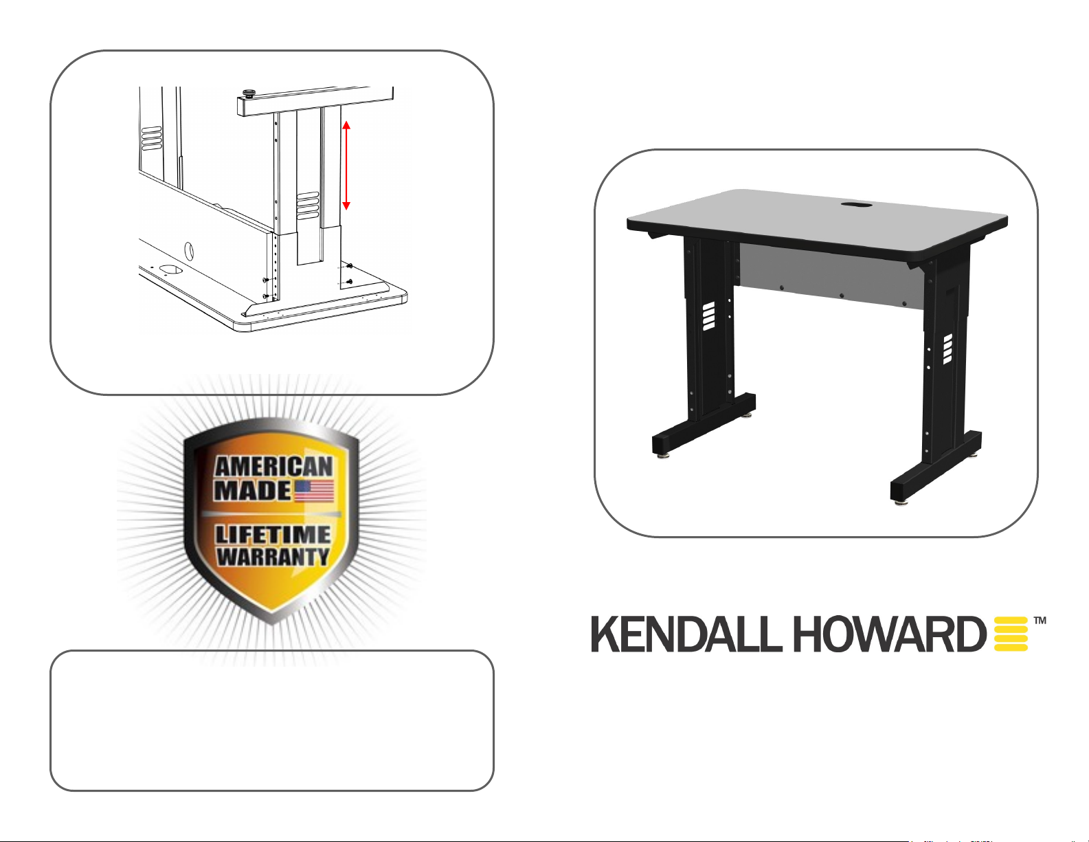
4
DISCLAIMER: Kendall Howard LLC. endeavors to make this manual accurate and complete. However, Kendall Howard LLC makes no representations or warranties of any
kind, expressed or implied, about whether the use of products contained herein would
infringe any rights or the correctness, accuracy or reliability of the information contained
herein or that said information covers all details, conditions or variations. The information
herein does not provide for every possible contingency in connection with the installation
or use of the product(s). The information contained in this document is subject to change
without notice or obligation. Kendall Howard LLC assumes no responsibility for the
accuracy, completeness or reliability of the information contained in this document. Any
reli a n c e p l a ced on th e i n f o rmation is t h e r e fo re stric t l y a t your ow n r i s k .
For details about product warranty, please visit www.kendallhoward.com
a. Set the training table height on each leg assembly by un-
screwing and sliding the leg to the desired position.
b. Re-insert screws to secure
Instructi on s / Directi on s
36” Training Table
# 5500-3-00X-XX
1
INN O V A TO RS I N PR OD UC T DE S IGN
w w w . k e n d a l l h o w a r d . c o m
A d d re s s : 1 0 15 2 Li be r t y L a n e
C h i sa g o C i t y , M i n n e s o t a , 5 5 0 1 3
U n i te d St a t e s o f A m e r i c a
P h o n e : 651- 213- 1333
F a x: 800- 418- 6897

Tools Needed:
2
Screw Driver
(4x) Leveler
(25x) 1/4-20 Screw
(4x) End Cap
(1) Modesty Panel
(1) Table Top
(1) Left Leg
Assembly
(1) Surface Grommet
Included:
(1)Right Leg
Assembly
(1) Modesty Panel
Grommet
a. Position table top with smooth surface facing down
b. Line up leg assemblies with pre-drilled hole pattern
(note - shorter side of legs face the back of the table)
c. Fasten to table top with 1/4” screws
* If installing the Cable Management Enclosure leave out back
two screws in the legs
Assembly - Step 1:
3
Assembly - Step 2:
a. Attach modesty panel to the back edge of the right and left leg
assembly. (Make sure the grommet opening is closest to the
work surface)
b. Fasten with 1/4” screws.
** If not installing the Cable Management Enclosure—fill in additional
threaded holes in modesty panel with additional screws.
Assembly - Step 3:
a. Insert levelers into the threaded inserts in the bottom of the leg
assemblies.
b. Insert end caps into base of each leg kit.
*If installing the Cable Management Enclosure, proceed to mount that to
the modesty panel before assembling the panel to the training table
 Loading...