

KENDALL SCD EXPRESS Operation Manual
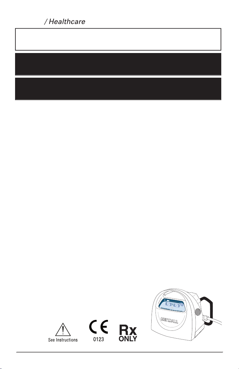
SCD EXPRESS
tyco
Användar- Och Servicemanual
ΣΎΣΤΗΜΑ ΣΥΜΠΊΕΣΗΣ
TLAKOVÝ SYSTÉM
Compression System
TM

TABLE OF CONTENTS
..........................................................................................................................
Contraindications
................................................................................................................
Cautions
..............................................................................................................................
................................................................................................
..............................................................................................................
Section I -
General Op
.............................................................................
3
t up
.............................................................................................................................................................................
.........................................................................................................................................................................
.............................................................................................................................
..........................................................................................................................................................
4
...........................................................................................................................................................
Vascular Refill Detection
...............................................................................................................................................
Compatibility
..................................................................................................................................................
4
Tubing Set Com
...............................................................................................................................................
4
.................................................................................................................................
Section II -
...............................................................................................
4
..............................................................................................................................................
5
.....................................................................................................................................................
5
...........................................................................................................................................................
Section III -
.................................................................
6
Watchdog Circuit
...........................................................................................................................................................
Section IV - Service and Maintenance
....................................................................................
8
...................................................................................................................................................................
Warranty and Factory Service
.......................................................................................................................................
............................................................................................................................................
..............................................................................................................................................................................
.............................................................................................................................................................
..........................................................................................................
......................................................................................................................................................................
...............................................................................................................................
..............................................................................................................................
Section V -
Test Methods and Cal
.............................................................................
0
Test Mode 01 - Burn-In
..............................................................................................................................................
Test Mode Look up Char
t
...........................................................................................................................................
Test Mode 02 - General Function Test
........................................................................................................................
Test Mode 03 - Pressure Transducer Calibration
........................................................................................................
Test Mode 04 - Pressure Transducer Calibration Verification
.....................................................................................

TABLE OF CONTENTS
Test Mode 05 -
.............................................................................................................................................
Test Mode 06 - Leak Test
............................................................................................................................................
Test Mode 07 - Performance Test
...............................................................................................................................
Test Mode 08
...........................................................................................................................
Section VI - General Disassembly / Reassembly
....................................................................
3
........................................................................................................................
.........................................................................................................................
Valve Manifold and Bed Hook (Removal / Installation)
............................................................................................
................................................................................................................................
...........................................................................................................
4
...................................................................................................................
.........................................................................................................
Section VII -
Specifications
..................................................................................................
Section VIII -
Schematics
.....................................................................................................
6
..................................................................................................
....................................................................................................................................................
............................................................................................................
Section IX -
................................................................................................
2
0
.................................................................................................................................................................
.................................................................................................................................................................
.................................................................................................................................................................
4
.................................................................................................................................................................
The SCD EXPRESS
TM
Compression System is designed to apply intermittent pneumatic compression to increase venous blood flow in
at-risk patients in order to help prevent deep vein thrombosis and pulmonary embolism. The System consists of the Controller, the Tubing Sets (provided
with the Controller) and single-patient use garments (purchased separately from this Controller). The garments, both leg sleeves and foot cuffs,
The use of the SCD EXPRESS Compression System with Leg Sleeves is indicated for:
Compression
The use of the SCD EXPRESS Compression System with Foot Cuffs is indicated for:
xtremity pain incident to trauma or surgery.
3. Edema - Acute. 7.
4. Edema - Chronic.
information regarding the SC
The SCD EXPRESS Compression System
be recommended for use with Leg Sleeve on patients with the following:
3. Massive edema of the legs or pulmonary edema from congestive heart failure.
4. Extreme deformity of the leg.
5. Suspected pre-existing deep venous thrombosis.
The SCD EXPRESS Compression System
be recommended for use with Foot Cuffs on patients with the following:
3. Pre-existing deep vein thrombosis, thrombophlebitis or pulmonary embolism.
3. Explosion hazard. Not suitable for use in the presence of a flammable anesthetic mixture with air or with oxygen or nitrous oxide.
WARNING:
s
the sleeves may occur
5,478,119; 5,876,359;
Tyco Healthcare
expressly states that no implied license with respect to
The use of
an intermittent pneumatic compression controller with a compression garment to measure venous refill time in a limb, without permission
from Tyco H
C
US
L
U
C
L
A
S
S
I
F
I
E
D
®
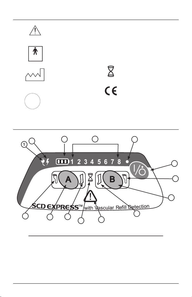
Type BF Protection Against
Vascular Refi ll Detection
0123
4
8
6
3
5
9
1 AC Power Indicator
2 Battery Charging Indicator
3 Battery Status Indicators 1-3
4 Test Mode/Error Code Indicators 1-8
5 Power On Indicator
6 Power On/Standby Button
7 Port B Foot Indicator
8 Port B Garment Confi guration Button
9 Port B Leg Indicator

Se
t up
• Place the Co
• The controller can operate with one or two garments attached to the patient.
• Plug the tubing set(s) into the back of the controller. Route the tubing toward the patient’s limbs, being careful to leave access ways clear and
• Plug the tubes into garment(s) wrapped onto the patient’s limbs.
•
atch the left and right ports with the left and right limbs of the patient. Although the operation of the controller
Plug
the
Start-up
• Press the Power On/Standby button to begin normal operation. If using leg sleeves, no further user intervention is required unless there is a fault
• The Controller will beep and then flash all the LED’s.
LED Indicator Sequence:
1. Port A Leg, Port A Foot, Port B Leg, Port B Foot , Vascular Refill, Battery Status 1-3
2. Port A Leg,
RED
3
RED
An automatic valve and pump test will be quickly performed as the system tests microprocessor function and system memory.
• The pump will begin to operate as part of the Garment Detection procedure.
’s responsibility.
Garment Configuration & Detection
After startup, the Garment Configuration procedure allows the user to select when foot compression is required at either of the two Controller ports:
•
s Leg indicator to turn off and the Foot indicator will be lit to signify foot
The configuration buttons need to be pressed only when foot compression is to be used.
Also after startup, the Controller immediately begins conducting the Garment Detection procedure at each port to determine if the garments have been
•
•
and normal operation begins by starting the compression therapy.
•
setting

• Verify that the corresponding Port Status Indicators are green for each disposable garment attached to the controller.
After garments have been
successfully detected, the Controller begins the process of applying intermittent compression alternating from on
the other if two garments are attached. Otherwise, the controller applies compression to only one port when one garment is attac
•
•
The Controller features microprocessor-controlled automatic pressure adj
The pressure setting depends on the type of garment: 45 mmHg for Leg Sleeves; 130 mmHg for Foot Cuffs.
Vascular Refill Detection
•
The SCD EXPRESS Compression System incorporates Tyco Healthcare’s patented “Vascular Refill Detection” method to customize the therapy for each
then used in subsequent cycles as the time between compressions.
• The vascular refill detection method is used when first powering on the System after it reaches set pressure and every thirt y minutes thereafter.
• The hourglass-shaped Vascular Refill Indicator on the front display will be illuminated during a measurement cycle.
• The method works best when the patient is still, however it will accommodate movement.
• If an error is detected during any measurement or if the compression is not within the System pressure specifications, the refill time measurement
will
• The time between compressions on the same limb will never be shorter than twenty seconds or longer than sixty seconds.
• If both Controller ports are being used, then the longer of the two measurements will
Garment
Compatibility
The SCD EXPRESS Compression System is designed for use with KENDALL garment Reorder Codes:
• 9530
Length)
•
Tear-Away)
•
•
5897 Foot Cuff (Regular Foot)
5898 Foot Cuff (Large Foot)
•
Tubing Set Com
The garments connect to the Controller via the Tubing Sets provided with the Controller. Additional or replacement Tubing Sets are available as Reorder
The SCD EXPRESS Compression System Controller can be configured without the bed hook for easier portability. The System can also be used
without
the cord cover door so that the power cord can be disconnected at the Controller instead of at the AC power wall outlet.
• An optional Shoulder Strap for the SCD EXPRESS Compression System is available as Reorder Code 9527.
Section II -
The SCD EXPRESS Compression System is designed to operate normally on AC line power or DC battery power without interruption. If the Controller
To prevent a potential shock hazard, the battery compartment should not be left vacant while operating the SCD EXPRESS Compres-
sion System. The battery pack, or a dummy pack (if so equipped), must be installed in the controller to prevent the user from having access
to the battery’s electrical connection.
for the SCD EXPRESS
Compression System is optional. To order
a
new or replacement battery
please contact Kendall Customer Service.
3
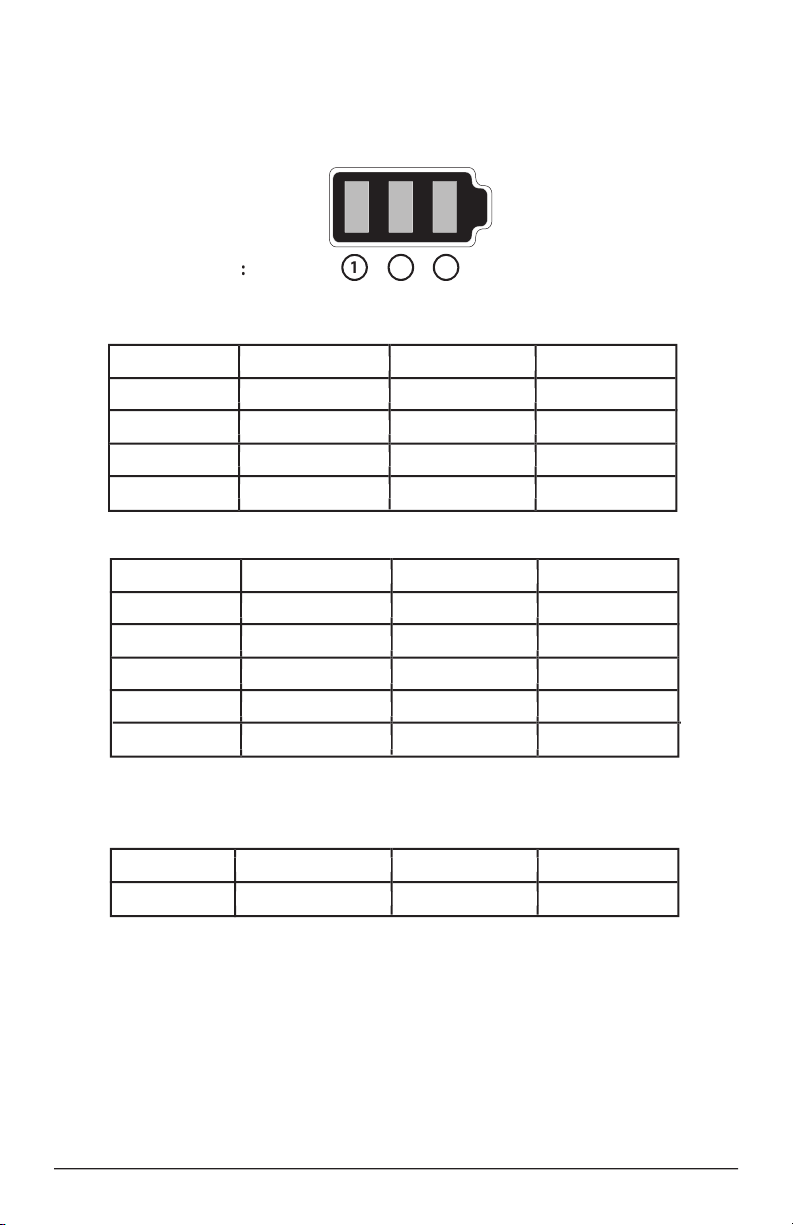
Battery State Battery Status 1 Battery S tatus 2 Battery Status 3
67-99% charge Green Green Green (Pulsing)
34-66% charge Green Green (Pulsing) Off
0-33% charge Green (Pulsing) Off Off
t plugged in and Powered On (Charging)
Battery State
34-66% charge Green Green Off
Powered Off (charging when plugged in)
Battery State Battery Status 1 Battery Status 2 Battery Status 3
0-100% charge Off Off Off
Charging the Battery
The battery will begin charging as soon as the unit is plugged into an AC power source. The amount of time required to charge the battery will vary
take approximately 4 hours with the controller on standby and 8 hours with the controller powered on. The Battery Status indicators should always be
The battery may sustain permanent damage and become unrecoverable if it is left
time. It is
the battery pack be stored with a minimum charge of 50% and kept near 25
° C
°F)
* With 15-40 minutes of battery charge left, an alarm will sound in a sequence of three beeps once every two minutes. Once
there is less than 15 minutes of battery charge left, the alarm will sound continuously.
 Loading...