

kENDALL Electric Cognex DataMan 260 User Manual

Kendall Technology Summit
2017
DataMan ID Basic and Advanced Labs
Featuring the DataMan 260


Table of Contents
Lab 1: Connecting to the DataMan reader . . . . . . . . . . . . . . . . . . . . . . 1
Lab 2: Tuning the reader . . . . . . . . . . . . . . . . . . . . . . . . . . . . . . . . . . . . 8
Lab 3: Symbology Settings . . . . . . . . . . . . . . . . . . . . . . . . . . . . . . . . . . 16
Lab 4: Read Setups . . . . . . . . . . . . . . . . . . . . . . . . . . . . . . . . . . . . . . . . 22
Lab 5: Data Validation . . . . . . . . . . . . . . . . . . . . . . . . . . . . . . . . . . . . . . 30
Lab 6: Buffering and Transferring Images . . . . . . . . . . . . . . . . . . . . . . 36
Lab 7: Trigger Modes . . . . . . . . . . . . . . . . . . . . . . . . . . . . . . . . . . . . . . . 42
i
Connecting to the DataMan Reader
Introduction:
This lab will show you how to start with a DataMan 260 reader that is at factory defaults, assign it an
IP address that matches your computer’s address and connect to the reader.
Start:
Your computer has a static IP address already assigned to it. One easy method for determining the
IP address of your computer is to use the Command Prompt and the command line ipconfig. This
will return the IP address and subnet mask (along with other related information) for all of the
Network Interface Cards (NIC) on your computer.
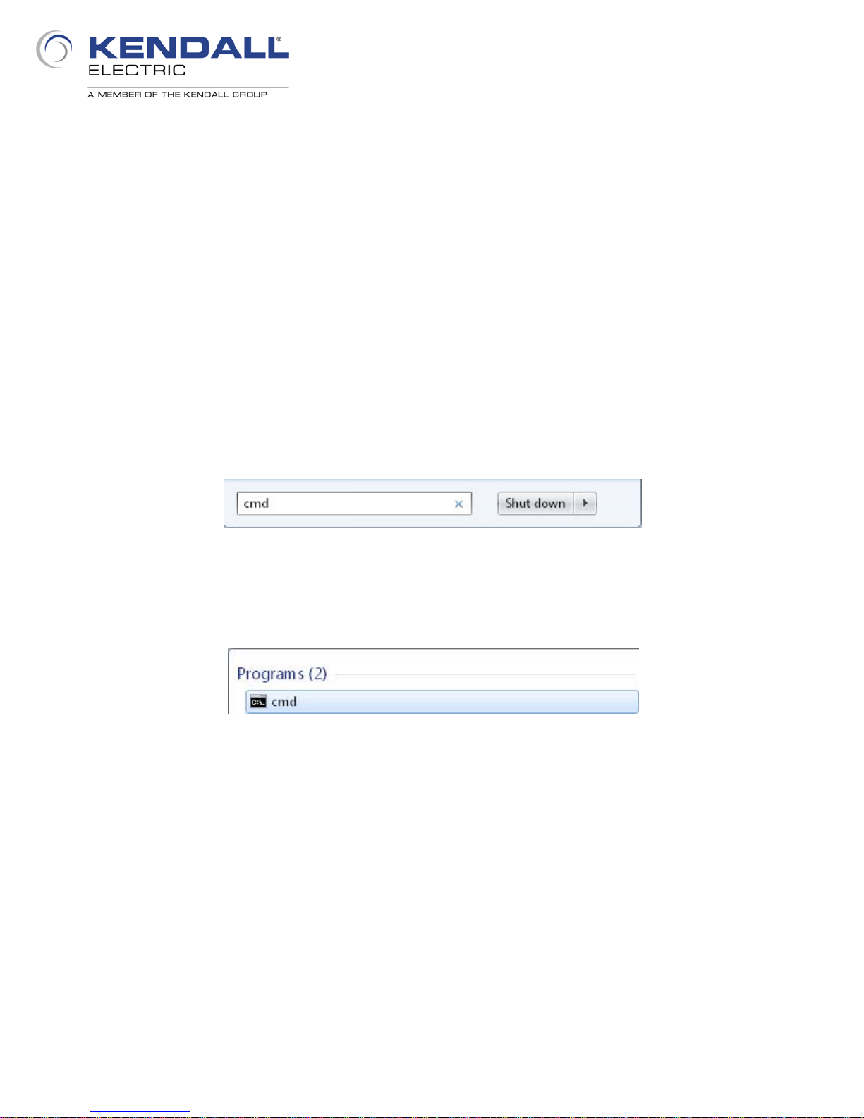
To determine the IP address of the wired NIC on your computer click on the Start menu and type
cmd in the search box at the bottom of the menu (Fig . 1).
As you type this, the pane above it will begin to populate with matches; at the top you should see a
selection for the Co mmand Line terminal (Fig. 2); click it to open the Command Line terminal.
When it opens you should see something like the image on the next page (Fig. 3).
Fig. 1 - Find Command Line
Fig. 2 - Launch Command Line
1
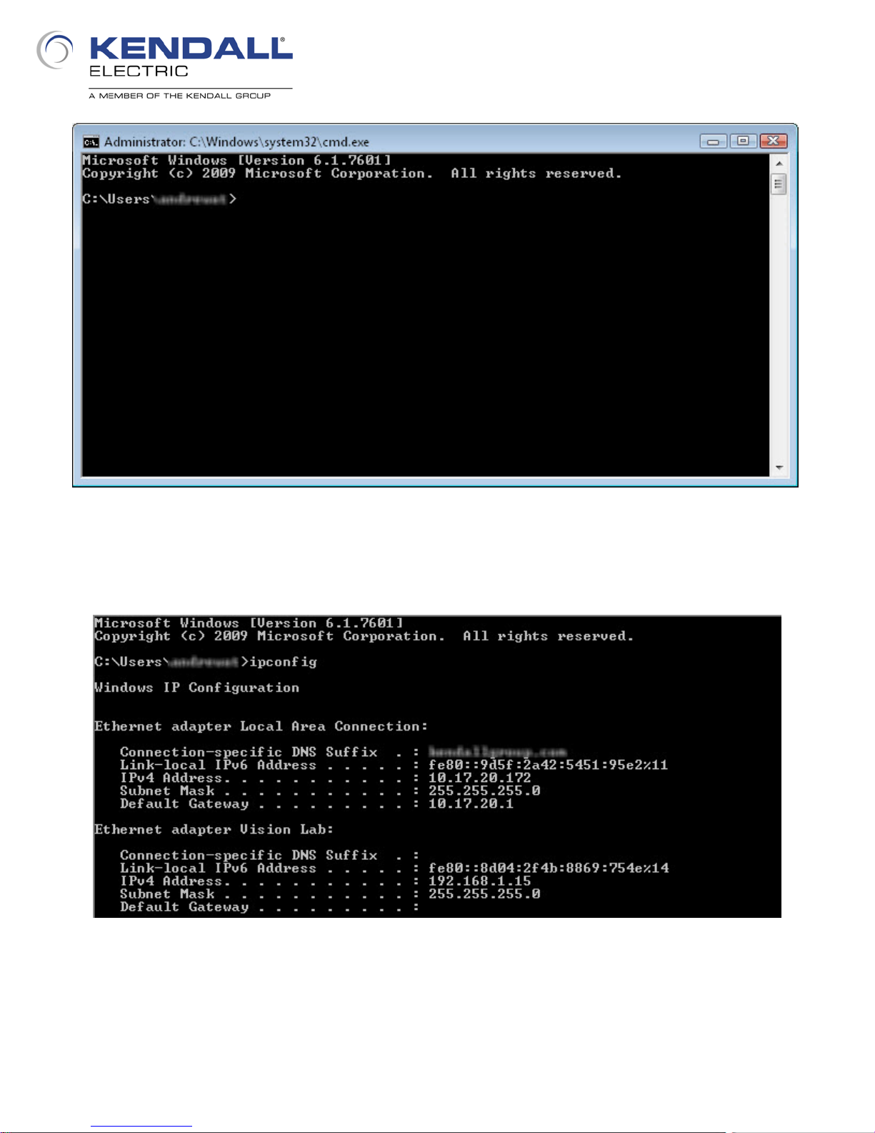
Fig. 3 - Command Line Terminal
At the cursor type the command ipconfig and press enter. You should see the window populate with
information about the available NIC’s, both wired and wireless (see Fig. 4).
Fig. 4 - IP Address Information
The above terminal window shows this computer has two NIC’s on different subnets, one of which
uses DNS and the other does not. Your computer may also have two, a wired and a wireless. Find
the IP Address and the subnet mask of the wired NIC and write them down.
2

The next step in the lab is to reset the reader to factory defaults; this will be accomplished with a
control code. Control codes are special codes that create a desired known state in a Cognex
reader. Regardless of whether a reader is configured to read Data Matrix codes or is natively
capable of reading Data Matrix codes, a control code will always be read. The code below (Fig. 5)
resets a DataMan 260/262 to factory defaults and can be found on the inside back cover of the
DataMan 260 Reference Manual. With the reader powered up, place this page beneath the
reader and align the code using the aimer LED’s. Press and hold the trigger button on the reader for
several seconds. As soon as you press it, the illumination LED’s will flash once and a couple of
seconds later they will flash multiple times; once you see this you can release the trigger button.
The reader will then reset and proceed to boot up.
Fig. 5 - Reset to Factory Defaults
At this point you can open the DataMan Setup Tool software by double clicking the icon on the desk
top. When it finishes opening you will see something like the image below (Fig. 6). This shows the
available devices that are connected via a serial connection and via an Ethernet connection. As the
factory default state for a Cognex reader is for DHCP to be enabled, the reader is stuck at a link
local address and does not appear in the list.
Fig. 6 - DataMan Setup Tool Connect Tab
3
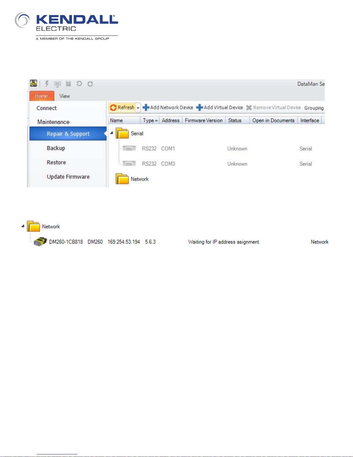
In order to assign the reader a static IP address, first click on Repair & Support under Maintenance
and if the reader is not immediately visible click the Refresh button (Fig. 7). By doing this the
network will be scanned for all devices and the reader should appear (Fig. 8).
Fig. 7 - Repair & Support Tab
Fig. 8 - Found Misconfigured Device
When a device is set for DHCP (Dynamic Host Configuration Protocol) and nothing serves it an
address it defaults to what is know as a link local address; this IP address takes the form of
169.254.X.X with a subnet mask of 255.255.0.0. as is seen here. Click on this device to highlight it
and in the pane on the right a dialog will appear where the address of the device can be changed
(Fig. 9 on next page).
4
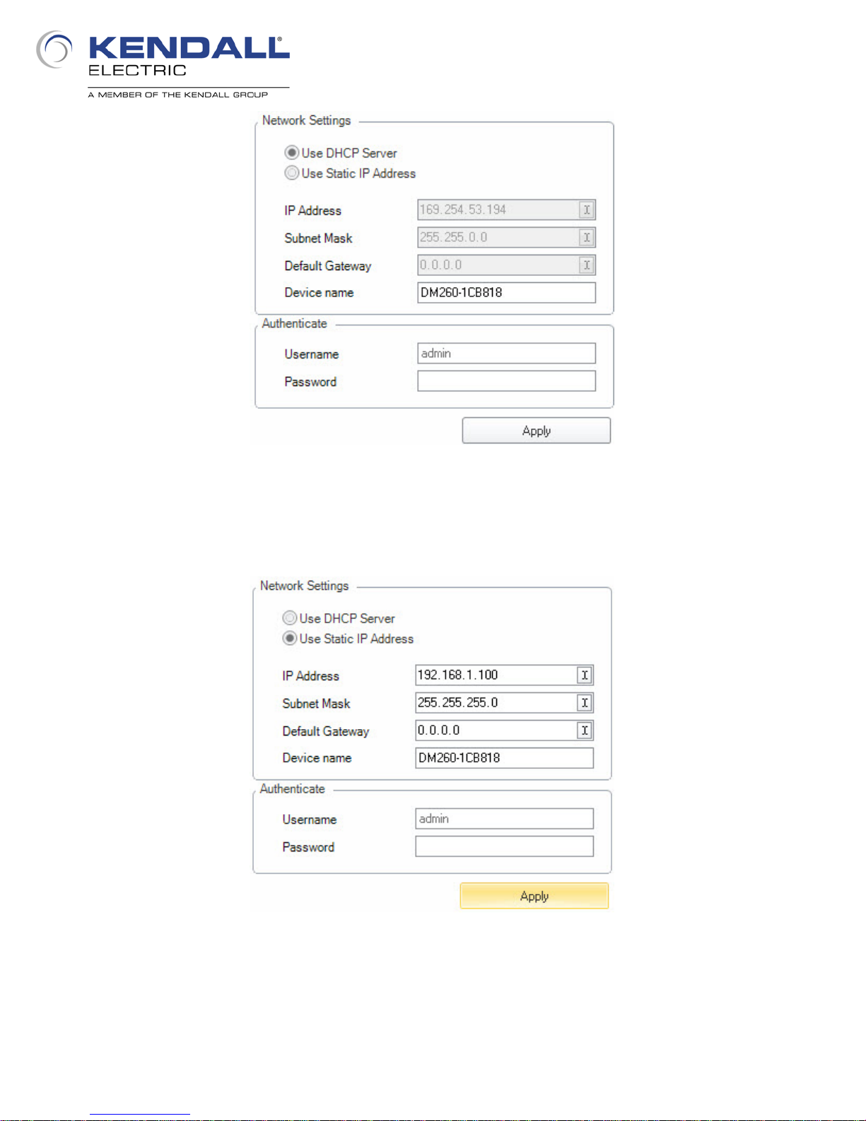
Fig. 9 - Current Device Settings
Select the Use Static IP Address radio button and enter an IP Address and Subnet Mask consistent
with your computers IP Address configuration (Fig. 10). You could create a username and
password if you desire; the default is as shown here. Click Apply.
Fig. 10 - New Device Settings
When you click Apply the command will be sent to the reader and after several seconds the reader
will disappear from the list. At this point the reader is restarting so that the new IP address can be
retained. After a couple of minutes it will finish the reboot and reappear with the new IP address set
(Fig. 11 on next page).
5
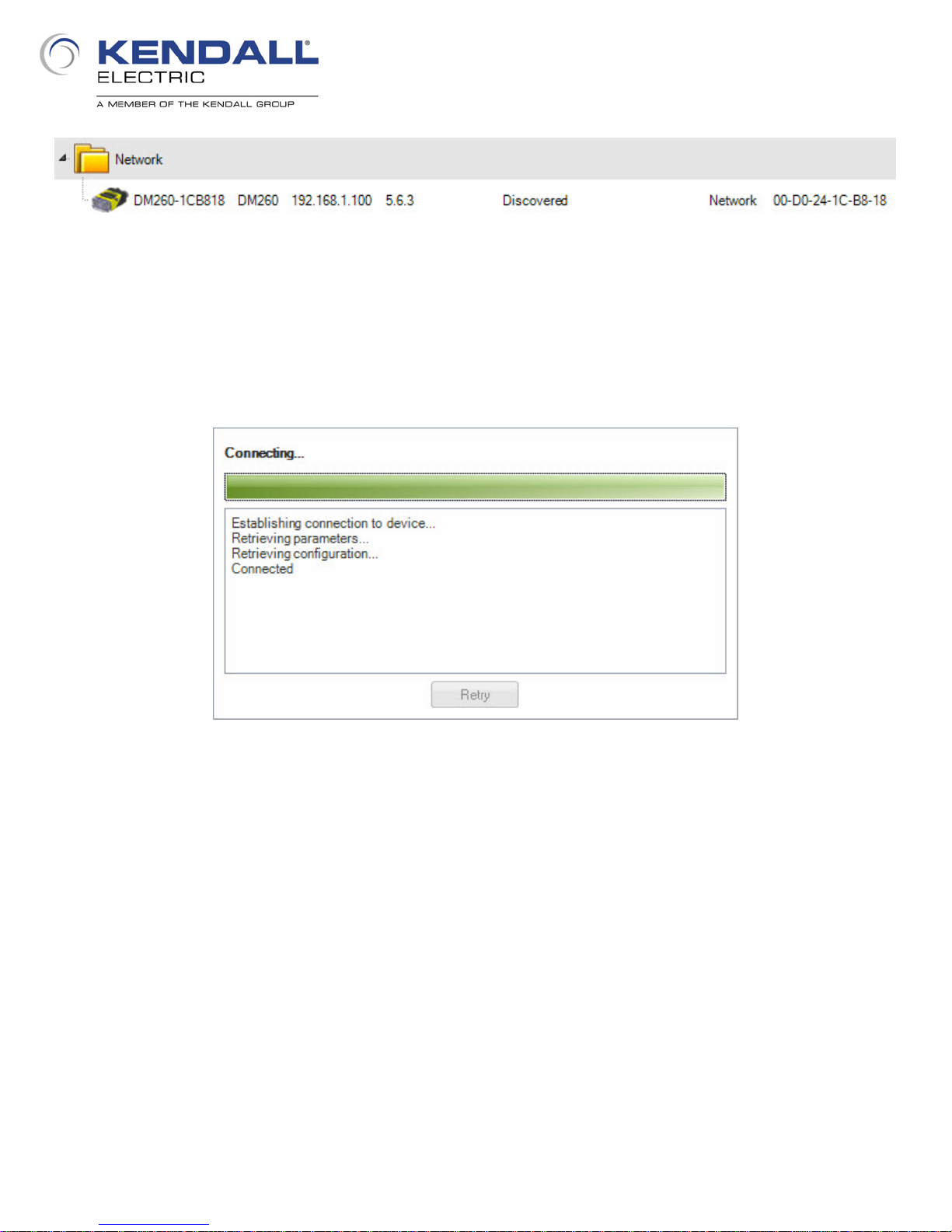
Fig. 11 - Properly Configured Device
You can now click on the Connect tab where the reader should also appear; click on it to select it
and click the Connect button in the lower right corner of the window. The software will then connect
to the reader. You should see a message box appear (Fig. 12) showing the connection status for
the reader and when it has finished connecting to the reader it will disappear and the software will be
ready to use to configure the reader.
Fig. 12 - Connection Status
Conclusion:
You have learned how to reset a reader to factory defaults, learned about control codes, learned
how to take a brand new reader and assign it an IP Address and connect to it.
6

7

Introduction:
The Tune function in the software and the Tune button on the reader allow for “optimally” setting a
variety of parameters to obtain an image in which the code can be reliably read without needing to
know much about the settings being made.
Start:
You have just connected to a reader that was reset to factory defaults. The software should have
the Settings tab in the ribbon selected with the Quick Setup view selected by default and it should
look something like the image below (Fig. 13). If it does not look like this you can turn on the various
panes from the View menu and dock them to the desired places in the traditional Windows manner.
Ask for assistance in changing the view if needed.
Tuning the Reader
Fig. 13 - Default Software View
8

Place the PowerGrid demo card under the reader so that the aimer lights are just below and
centered horizontally on the Cognex logo. Click the Live button. You should see the illumination
LED’s on the reader strobe to capture images of the card and in the image on the Quick Setup tab
you may see the image change from complete white (saturated) to one in which the card is
reasonably contrasted and the bottom middle code is being read (Fig. 14). Some preliminary
settings have already been made to achieve a readable image.
Fig. 14 - Live Mode
Click the Live button again to turn off live mode. Next press and release the Tune button on the
reader (Fig. 15). Notice that the aimer lights have been turned off. Press and release the Tune
button to turn the aimer lights back on.
Fig. 15 - Tune Button
9

Next press and hold the Tune button on the reader to initiate the tuning sequence; this will take
about five seconds and you will see the illumination LED’s begin to flash. In the tuning sequence the
following things will be accomplished.
Optimize focus (when liquid lens module is installed)
Optimize brightness
Test different exposures (both gain and exposure time)
Plot decode results on the graph
Automatically apply the optimum settings when finished
The graph may appear something like the one below (Fig. 16). The dots represent decodes at
different settings and the dots above the decoding threshold are good reads; those below are no
reads. Dots that are higher on the graph represent settings that provide more reliable decoding.
Fig. 16 - Tuning Results
Click the Trigger icon in the menu bar (Fig. 17) to trigger a read, assuring that the good code can
indeed be read. Now cover all codes but one and trigger the reader again to insure that a different
code can be read. Repeat this until all of the codes on the card are read.
Fig. 17 - Trigger Hotkey
10
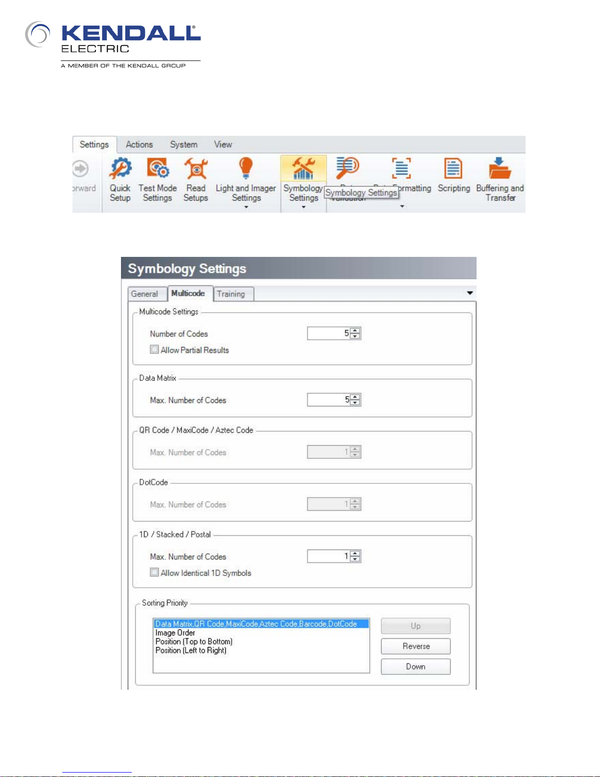
Now click on the Symbology Settings button in the ribbon (Fig. 18) to open the Symbology Settings
dialog. Click on the Multicode tab (Fig. 19). Increase the Number of Codes to be read to five and
the number of DataMatrix codes to be read to five.
Fig. 18 - Symbology Settings Menu
Fig. 19 - Symbology Settings Dialog
11
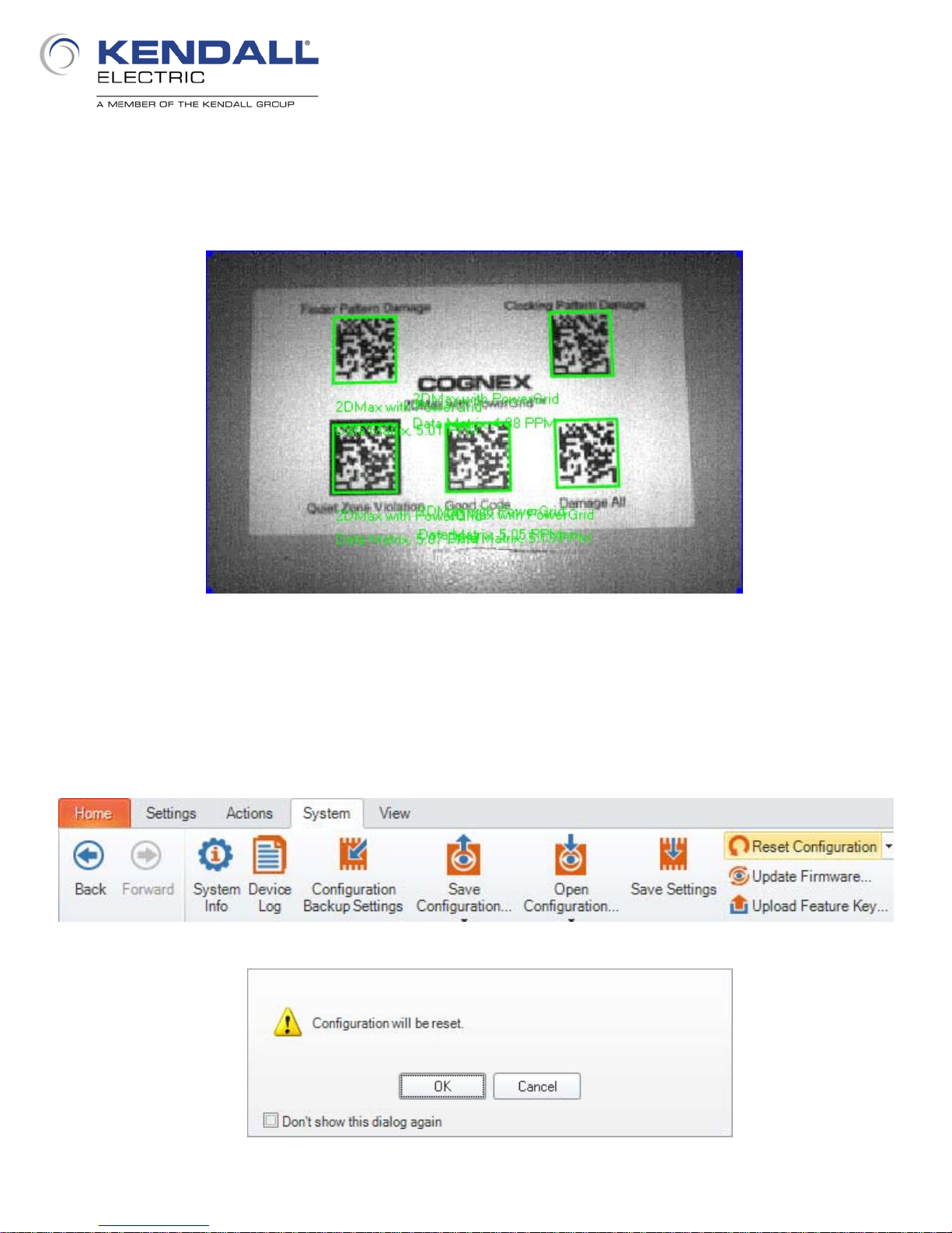
Return to the Quick Setup pane and again trigger the reader using the Trigger hotkey. Notice now
that all five codes are read (Fig. 20). Notice that on the Multicode tab that more than one type of
code can be decoded in the field of view at one time. Additionally the reporting of the read codes
can be sorted in different manners, including by type of code or by position (see bottom of Fig. 19).
Fig. 20 - Five Codes Read
That is the basics of tuning and the idea is that right out of the box, without much work or even much
understanding of the system, you can have the system optimized to read your codes. Now let’s look
at tuning in a bit more detail that can help customize the system according to your needs. The first
step will be to reset the reader configuration. This clears anything we have set previously that might
affect the next steps of the lab exercises. Start by clicking on the System menu and then the Reset
Configuration button (Fig. 21); confirm the reset by clicking OK (Fig. 22).
Fig. 21 - Reset Configuration
Fig. 22 - Confirm Reset
12
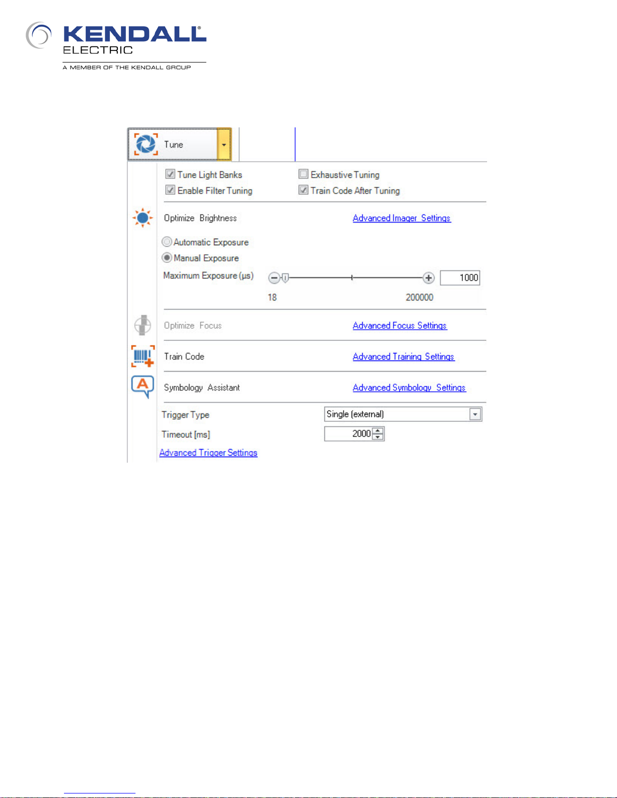
When the reader has been reset the image on the Quick Setup pane will go back to being all white.
From the Quick Setup pane click on the arrow at the right side of the Tune button to open up the
pane with the tuning options (Fig. 23).
Fig. 23 - Tune Settings
Tuning the reader can be accomplished from the software as well as the Tune button on the reader.
From the software you can also customize how the system is tuned. At the top of the dialog are
options for what is performed in the tuning process. By default the code is trained when tuning is
performed. Training the code includes:
Training the symbology type
Training the number of pixels per module
For 1D codes, their orientation
For 2D codes, the grid size.
Codes with properties that differ from the trained properties will not be read. For the properties that
can have slight variations, there is some tolerance of the variation (orientation of 1D codes) before
the code is not read.
Enabling filter tuning allows the addition of image processing filters to be used in the decode
process; this can increase decode time so it may not be desirable in all situations. Exhaustive
tuning allows for a more thorough testing of possible light and exposure combinations to choose
something other than the first one that allows a decode.
13
Each of the items that can be tuned has a link to advance settings; these are quick links to dialogs,
that can also be accessed through other menus, which allow for manual adjustments to tuned
settings. Items that are grayed out are properties that can’t be changed for the connected device (if
no liquid lens is installed then the focus can not be optimized through the software).
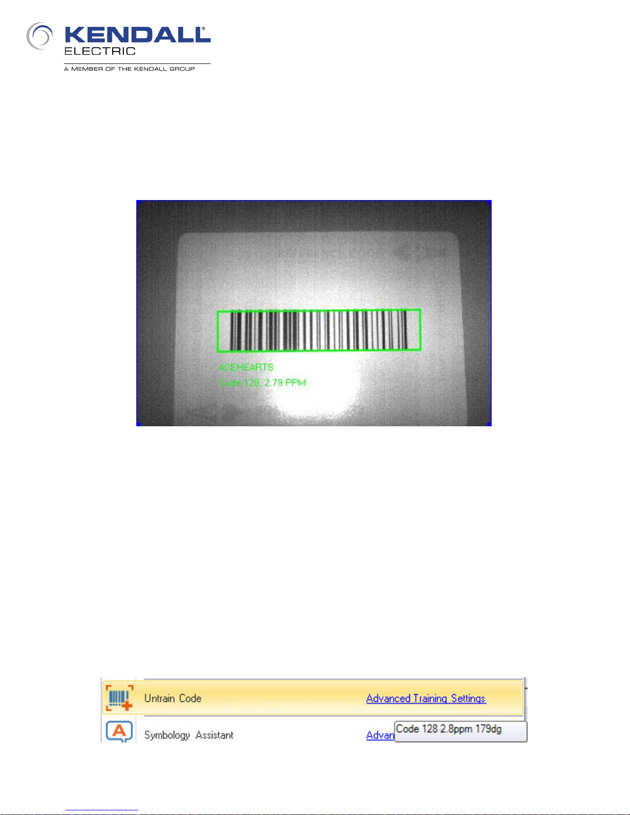
Place the Ace of Hearts from the deck of cards in the field of view using the aimer lights to position
it. Click the Tune button on the Quick Setup pane and wait for the tuning process to finish. You
should see something like the image below (Fig. 24).
Fig. 24 - Ace Of Hearts - Tuned
Turn the card slightly (a few degrees) either clockwise or counterclockwise and trigger the reader.
Does it still read the code? Turn it a bit more and trigger the reader again. How far can you turn it
before the code is no longer read? Place the Ace of Diamonds beneath the reader and trigger the
reader. Did it read the code?
Tuning the reader also trained the code present on the Ace of Hearts. Though the code type on the
Ace of Diamonds is the same symbology as on the Ace of Hearts (Code 128), the codes are
different sizes. Additionally the orientation of the code was trained, so turning the Ace of Hearts too
much causes it to not be read.
Click the down arrow next to the Tune button in the Quick Setup pane and hover over the link that
says Advanced Training Settings (Fig. 25) and notice the tool tip that appears. This shows
information about the code that was trained including the angle at which the code was positioned at
time of training.
Fig. 25 - Code Training
14
 Loading...