

Page 1
KENCO ENGINEERING COMPANY
P.O. BOX 470426 TULSA, OK 74147-0426 ● PHONE: (918) 663-4406 FAX: (918) 663-4406
www.kenco-eng.com e-mail: info@kenco-eng.com
MODEL KWR AND KWT WELD PAD STYLE FLAT GLASS GAUGES
INSTALLATION / OPERATION INSTRUCTIONS
GENERAL DESCRIPTION
Kenco Flat Glass Gauges are simple, rugged instruments engineered and constructed throughout to give you accurate
liquid level readings for the life of the vessel. We offer a complete range of gauges suitable for most applications. Like
any instrument, Kenco flat glass gauges must be installed, operated, and maintained with reasonable care and due regard
for the application, and the environment, if they are to give accurate readings over a long life.
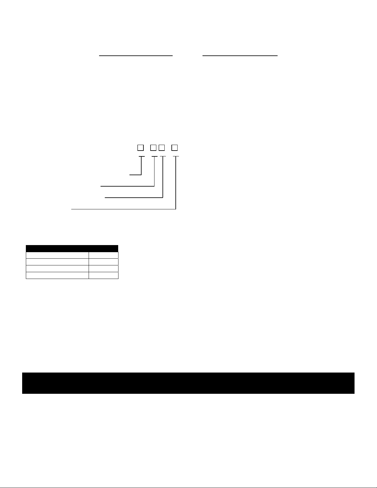
MODEL CONFIGURATOR
Style (R – Reflex; T- Transparent)
Sections – (1 through 9)
Glass Size – (1 through 9)
Construction
Construction
Material Code
Carbon Steel C
Stainless Steel Wetted W
All Stainless Steel A
Special S
INSPECTION & DELIVERY
Upon receiving the gauge, check all components carefully for damage incurred in shipping. Notify the shipping company
immediately of any such damage, and request a damage inspection. Confirm that the gauge model number and
pressure/temperature ratings (located on the nameplate) match the application conditions. Also, confirm that the gauge
materials are compatible with the process media and the environmental conditions around the gauge.
CAUTION – Kenco Gauge Glasses are not to be used for indicating the level of lethal substances as defined
by ASME Section VIII.
K W - -
Page 1
Page 2
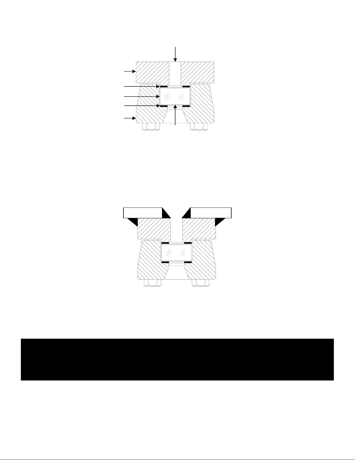
GAUGE CONSTRUCTION
Weld Pad Gauge (Model KWR & KWT)
Vessel Slot
Chamber
Gasket
Glass
Cushion
Cover
Glass
Reflex or Transparent
WELDING INSTRUCTIONS
Weld Pad Gauges are shipped loosely assembled and should first be entirely dismantled. The pad may then be used as
a template for laying out the vision slot which is to be cut through the wall of the vessel. If internal welding is to be
performed (recommended), the width and length of the slot can be increased by chalking a second cutout line ¼” away
from the scribed line obtained in tracing the vision slot. This will provide a suitable shelf in which to lay the bead, as
shown in the following drawing
To avoid buckling, the pad should be tack welded at intervals, both internally and externally, in accordance with
recognized welding procedures, before placing the continuous welds. As an added precaution against distortion, the
welding pad gauge can be assembled without gaskets, using a steel spacer instead of the gasket-glass-cushion
assembly. This spacer can be cut from bar stock 1¼” X ¾”. The length will be determined by the length of the gasket
recess. This procedure will increase the rigidity of the pad and minimize the possibility of distorting the glass seating
surface.
CAUTION – Standard weld pad gauges will withstand loadings due to the pressure within the gauge itself, but
they are not designed to replace the vessel strength lost when the vessel wall is cut. Kenco has
no control over the loading which the vessel will impose on the pad. It is therefore impossible to
rate welding pad gauges. The vessel fabricator must provide suitable vessel wall reinforcement
to prevent the pad from being distorted during welding, or while under operating conditions.
Page 2
Page 3

ASSEMBLY INSTRUCTIONS
Assemble the gauge in accordance with the drawings in the “GAUGE CONSTRUCTION” section. Tighten the center
screws to 5ft./lbs. and then, working toward the alternate ends (see drawing below), tighten the remaining bolts. The
torque wrench can then be set to 10ft./lbs. and the same procedure followed. A final setting of 25ft./lbs. is generally
sufficient to prevent leakage at the maximum pressure to which the vessel will be subjected.
MAINTENANCE
The following is a step-by-step procedure for maintaining your Kenco Weld Pad Flat Glass Gauges:
A. Inspection of Glass:
Look at the glass regularly for any signs of clouding or scratching. In new processes, the glass should be inspected
daily until the need for replacement becomes apparent. This will help establish the routine inspection / maintenance
cycle.
To examine for scratches, shine a very bright concentrated light (e.g. MagLight) at a 45° angle. Anything that
glistens brightly should be inspected closely. Any scratch which catches your fingernail, any star-shaped or
crescent-shaped mark which glistens is cause for replacement. If inner (process side) surface appears cloudy or
roughened and will not respond to cleaning procedures (next section), this could be an indicator of chemical attack
and, if severe, is cause for replacement.
B. Cleaning of Glass
Keep glass clean using commercial glass cleaners (e.g. Windex, Bon-Ami). If these don’t seem to work, a dilute
solution of Hydrochloric (muriatic) acid can be used. Observe safety rules when handling these dangerous
chemicals. Cleaning should be done without removing the glass. This may require recirculation of cleaning
materials if the process side of the glass is not accessible. Never use harsh abrasives, wire brushes, metal
scrapers, or other things which could scrape the glass.
CAUTION – DO NOT attempt to clean the glass while the gauge is in operation.
C. Receiving and Storing Glass
Upon receiving replacement glass inserts, inspect containers and glass inserts for shipping damage. Keep glass in
original box until ready for use. If glass is to be inspected, unwrap and re-wrap carefully, avoiding bumping or sliding
polished face across any other object (including table tops).
D. Disassembly
Prior to any disassembly of the gauge, first be sure that the gauge is relieved of all internal pressure, and that the
gauge is at ambient temperature. Loosen end screws first, working from opposite ends toward the center.
CAUTION – Failure to relieve pressure may result in a sudden release of internal pressure, which can cause
physical injury, and/or glass breakage..
12 14
13711 13
248
59
610
Page 3
Page 4

E. Reassembly Guidelines
NOTE: See the section on “GAUGE CONSTRUCTION” for the location any parts discussed below.
Kenco gauges use molded borosilicate glass, tempered to increase its bending resistance. This glass has a low
coefficient of expansion and is more resistant to thermal shock than other glasses. Nevertheless, like any glass it is
much stronger in compression than it is in tension. You should be careful not to impose any bending on the glass, or
set up any local stresses. The following points should be observed to insure long life:
• Check with the Maintenance Supervisor or Engineer for the proper glass to be used in the gauge. Check
box and glass labels or marking against the gauge pressure and temperature ratings.
• The glass, gaskets, cushions, and screws should not be reused, even when they appear in perfect condition.
Replace with new parts. Bolts will stretch when re-torqued, thereby weakening them. Glass deforms under
pressure from the chamber and cover. Even though a used glass may look perfect, it is not as reliable as a
new one. Best practice is to always use a new glass.
• The glass should be seated on a flat surface with a suitable gasket on the seating surface to avoid
subjecting the glass to stress concentrations which result from poor loading. It should be clamped in place
with a flat cover plate that is uniformly loaded, as described in the “Reassembly Procedures” below.
• The glass should not be in contact with any metal surfaces.
• For transparent gauges used in steam service, use mica shields between the glass and gasket on the
chamber (process) side.
F. Reassembly Procedure
To avoid leakage and undue stresses on the glass, we recommend the following reassembly procedure:
1.) Before reassembly, clean the gauge chamber seats and cover seats thoroughly with a soft metal scraper,
preferably brass. Be sure all burrs and bits of old gasket are removed. Gouged or scarred seats should be
refinished in a milling machine (or you can return the chamber to Kenco for refinishing). Damaged seats cause
low gasket compression and leakage.
2.) Locate the glass centrally in chamber and cover seat, to avoid glass-metal contact at the ends or sides. Use a
rubber band around the sides and ends of the glass. This will prevent glass-metal contact during assembly.
3.) With a torque wrench, replace the gauge covers as follows:
a.) Clean bolt threads, and apply a light oil to the threads and nut face. For gauges operating at more than
150°F, use Molykote or a similar molybdenum disulfide lubricant.
b.) Tighten the nuts finger-tight in the sequence shown in the “ASSEMBLY INSTRUCTIONS”, and then tighten
with a torque wrench in the same sequence. Tighten the nuts in five-pound stages. This procedure
produces even loading of the glass.
c.) Recommended final torque values: 25ft./lbs.
d.) New rubber-bonded gaskets tend to become permanently compressed after a short time in service. This
causes slight leaks or apparent loosening of the bolts. Therefore, re-torque to the original value after the
gauge has been in service for a few hours, using the same sequence as before.
Page 4
 Loading...