

Page 1
KENCO ENGINEERING COMPANY
P.O. BOX 470426 TULSA, OK 74147-0426
PHONE: (918) 663-4406 FAX: (918) 663-4480
Web: www.kenco-eng.com e-mail: info@kenco-eng.com
MODEL KPFS LIQUID LEVEL FLOAT SWITCH
VALVE REPLACEMENT KIT INSTRUCTIONS
RK-VALVE-KPFS VALVE REPLACEMENT KIT
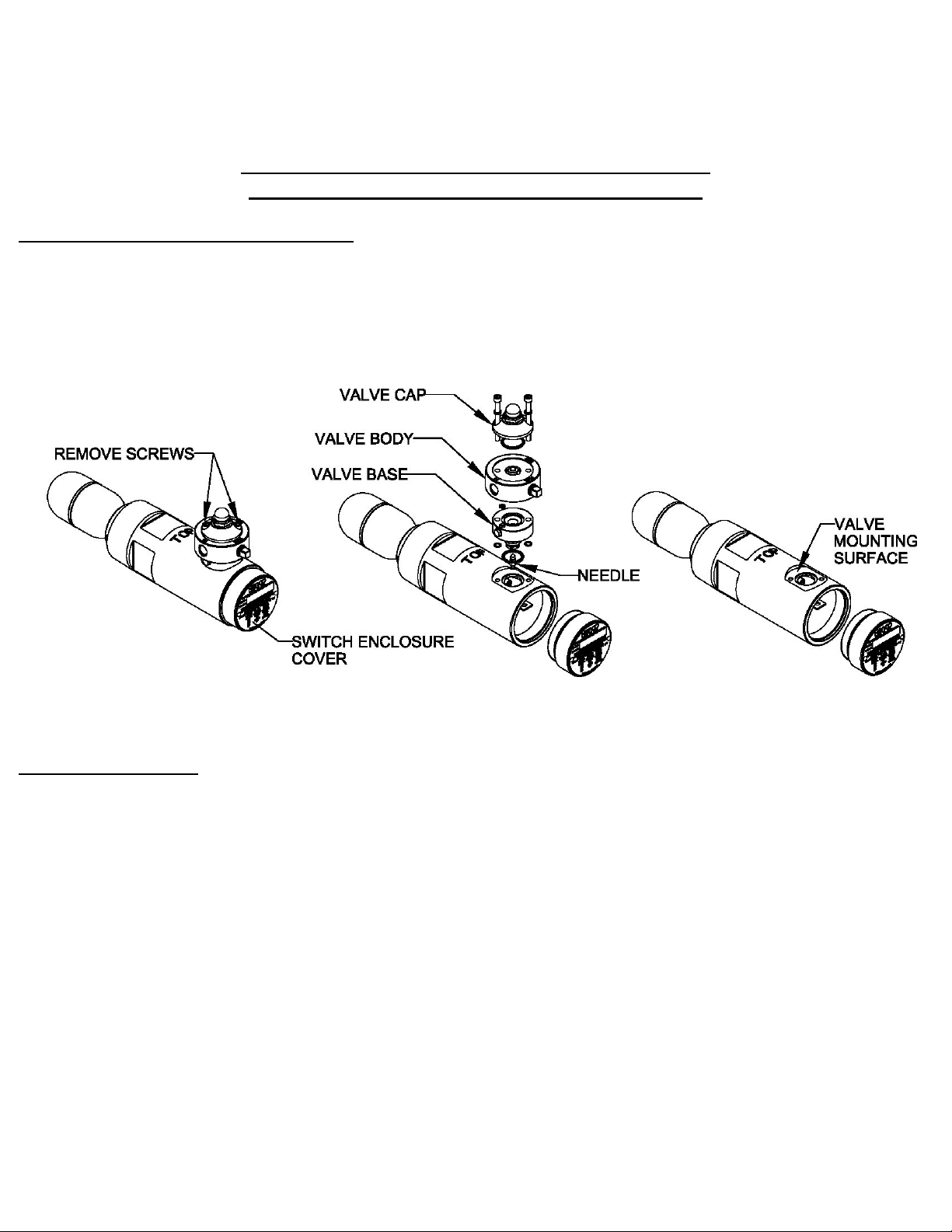
The RK-VALVE-KPFS is the Valve replacement kit for the Kenco pneumatic float switch model KPFS. The Valve is made up of
three main components. These components can be seen in the middle view of Figure 1 and consist of the Valve Base, Valve Body
and Valve Cap. There are two screws that hold the KPFS to the Switch Body. These two screws also serve as the screws that hold
the valve assembly together. Because of this, each of the three Valve components are assembled to the Switch Body one at a time
until all three components are in place, then the two screws are installed to clamp the Valve assembly together and secure it to the
Switch Body. To get started with the assembly, the old Valve must first be removed.
Figure 1
Refer to the illustrations in Figure 1 for the Valve removal process.
To remove the old Valve
1. Turn off the supply line pressure to the Valve if system is pressurized.
2. Disconnect the supply and outlet lines. Disconnect the exhaust line if equipped.
3. Remove the Switch Enclosure Cover.
4. Remove the two screws holding the Valve assembly in place and discard.
5. Remove the Valve Cap, Valve Body, Valve Base, all of the O-rings and discard.
6. The Needle will be loose and probably laying inside the Switch Enclosure. Locate the Needle and discard.
7. Make sure the valve mounting surface on the Switch Body is clean and free of any dirt or debris. The KPFS
is now ready to have the new Valve installed.
:
[1]
(64285 Rev A)
Page 2
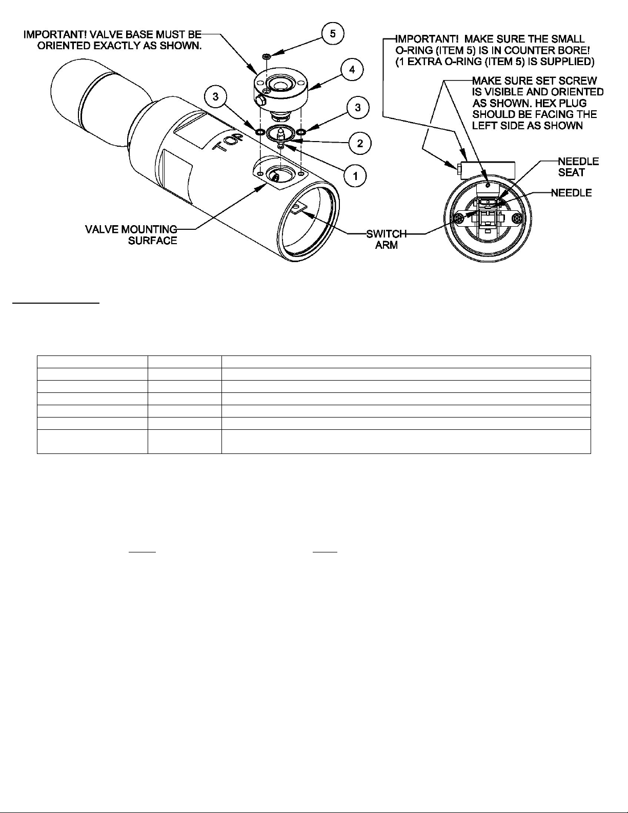
Figure 2
Install Valve Base
1. Locate the parts bag that contains the Valve Base, Valve Base O-Rings and Needle. It will contain the following parts: Notice
that only one o-ring per (item #5) is needed but two are supplied. This is because it is a very small o-ring and if dropped may
be difficult to find.
ITEM NUMBER QUANTITY DESCRIPTION
1 1 NEEDLE
2 1 O-RING, ¾” DIAMETER
3 2 O-RING, ¼” DIAMETER
4 1 VALVE BASE
5 1 O-RING, 13/64” DIAMETER (SMALLEST O-RING, 1 EXTRA IS SUPPLIED)
NOT SHOWN 1
2. Insert the o-ring (item #2) into the large counter bore in the valve mounting surface on the Switch Body. It is the counter bore
directly under item #2 in Figure 2.
3. Lay one each of the two o-rings (item #3) on the valve mounting surface on the Switch Body. Line each of the o-rings up
with one each of the threaded holes on the valve mounting surface. (Alternate method: Apply grease to o-rings and place
them in the o-ring counter bores on the bottom of the Valve Base. The grease will hold the o-rings in place during assembly).
4. The object of the next few steps is to set the Valve Base down onto the valve mounting surface and over the top of the
Needle. In order to do this, the Needle must be positioned directly under the large hole in the valve mounting surface. This is
accomplished by gently
grasping the needle with a pair of clean hemostats (or needle nose pliers). Take care not to contact
the rubber tipped end. If the rubber tipped end gets damaged, the KPFS may leak and not operate properl y. While holding
onto the hemostats, insert the Needle into the Switch Enclosure with the rubber tip facing up. Position the Needle directly
under the hole in the valve mounting surface.
5. Noting the orientation of the Valve Base in Figure 1, carefully insert the Valve Base into the hole in the valve mounting
surface while at the same time gently guiding the Needle into the Needle Seat.
6. As you get close to setting the Valve Base down onto the valve mounting surface, make sure that the Valve Base is oriented
exactly as shown in figure 1 and that the o-rings (item #3) fully seat into the counter bores on the screw holes in the Valve
Base. As the Needle Seat is guided over the Needle, release the Needle and remove the hemostats. The Needle should be
captured between the Needle Seat and the Switch Arm.
7. With the Valve Base fully seated and properly oriented, place the o-ring (item #5) into the small counter bore on top of the
Valve Base as shown in figure 2.
.050” “L” SHAPED HEX ALLEN WRENCH (REPLACEMENT OF ALLEN
WRENCH SUPPLIED WITH KPFS IN CASE IT IS MISSING OR WORN OUT)
[2]
Page 3

Figure 3
Install Valve Body
1. Locate the parts bag that contains the Valve Body. The Valve Body will be the only part in the bag.
2. Check the orientation of the Valve Base from the previous section. Make sure the hex plug is to the left of the Switch Body
when viewed from the open end of the switch enclosure as shown in Figure 3. The set screw on the Valve Base should also
be visible.
3. Now place the Valve Body on top of the Valve Base exactly as shown. The text on the Valve Body should be facing up and
the exhaust port with the square plug should be facing the rear of the KPFS as shown in Figure 3. There is a diaphragm on
the bottom of the Valve Body (not visible in figure 3). The diaphragm will fit into the diaphragm seat on top of the Valve Base.
Make sure the diaphragm is fully seated into the Valve Base and that the Valve Base and Valve Body are properly oriented.
Figure 4
Valve Final Assembly
1. Locate the parts bag that contains the Valve Cap. It will contain the following parts.
ITEM NUMBER QUANTITY DESCRIPTION
7 1 O-RING, 13/16” DIAMETER
8 1 VALVE CAP ASSEMBLY
9 2 LOCKWASHER, STAINLESS STEEL
10 2 CAPSCREW, NO. 8 X 1-3/4” LONG STAINLESS STEEL
2. Verify the orientation of the Valve Base and Valve Body. Make sure the bolt holes in the Valve Body are lined up with the
bolt holes in the Valve Base.
3. Insert the o-ring (item #7) into the o-ring groove on the bottom of the Valve Cap. Note: O-ring groove not visible in figure 4.
4. Place the Valve Cap on the Valve Body and line up the bolt holes as shown in Figure 4.
5. Install the Lock Washers (item #9) onto the Capscrews (item #10).
6. Loosely install the Capscrews into the bolt holes on the Valve. Start the threads on the Capscrews but do not tighten them.
7. The object of the next step is to make sure the two Capscrews are tightened down evenly. If one is tightened before the
other it can create an uneven load on the diaphragm and the Valve will not function properly. While holding onto the Valve
Cap with one hand, use a 9/64” hex key wrench in your free hand to turn one of the Capscrews until it just comes into
contact with the Valve Cap.
8. Now move the 9/64” hex key wrench to the other Capscrew and tighten it until it just contacts the Valve Cap.
9. At this point, both Capscrews should just be touching the Valve Cap. Moving back and fourth between the two Capscrews,
tighten each one approximately ½ turn at a time until they are both securely tightened.
[3]
Page 4

Figure 5
Valve set up
Note: For safety reasons, KENCO Engineering recommends the use of air only when setting up the valve. If natural gas is
being used as the supply gas, temporarily connect a portable air tank pressurized with air to adjust the switch. Make sure
the supply pressure is within the rated range of 30-75 PSI and the air is clean and dry. Once the switch is adjusted,
disconnect the portable air tank and reconnect the supply gas.
Make sure the Switch Float is in the “Valve Closed” position. On the KPFS-LR model, the Switch Float will need to be in the
down position. On the KPFS-LF model, the Switch Float will need to be in the up position. You will know which model you
have by the model number on the Switch Enclosure Cover name tag. In addition to this, the KPFS-LF has a counter weight
attached to the Lever Arm and the KPFS-LR does not. See illustrations in Figure 5.
Turn off the air supply line pressure to the switch if system is pressurized.
Remove the Switch Enclosure Cover on the end of the switch body.
Remove the 0.050” “L” Shaped Hex Allen Wrench from inside the Switch Enclosure Cover by loosening the Wrench
Retaining Screw.
Using the 0.050” “L” Shaped Hex Allen Wrench supplied with the switch, loosen the Hex Socket Head Set Screw located at
the 12 o’clock position inside the switch enclosure.
Important
: Only loosen the Hex Socket Head Set Screw 1 to 1-1/2 turns.
The Adjustable Needle Valve Seat is designed to be raised and lowered using the “L” Shaped Hex Allen Wrench supplied
with the switch. There are six holes in the seat and you can only turn one hole at a time. It takes six turns to rotate the seat
one complete revolution. A good starting point for adjustment is to raise the Needle Valve Seat until it bottoms out against
the Valve Base. Insert the long end of the wrench into one of the holes in the Needle Valve Seat and turn it to the right as
far as possible before moving the wrench to the next hole.
Once the Needle Valve Seat is bottomed out against the Valve Base, lower the Needle Valve Seat 6 turns to the left or one
complete revolution.
Important
: Great care must be taken here. If the Needle Valve Seat is lowered so much that the Lever Arm is in
a bind, damage to the Needle and/or Lever Arm can occur. During adjustment, continuously check the
movement of the Lever Arm by gently toggling it with your finger to make sure it moves up and down freely. If
the Lever Arm does not move up and down freely, the Needle Valve Seat has been lowered too much and has
the Lever Arm in a bind. If this is the case, raise the Needle Valve Seat by turning the wrench to the right until
the Lever Arm moves freely.
With this starting point established, pressurize the system somewhere within the 30-75 psig switch pressure range.
Air should be leaking from the Needle Valve Seat. If it is not, toggle the Lever Arm and/or Switch Float to verify that the
valve is shifting properly.
: If air is still not leaking from the Needle Valve Seat, raise the seat by turning the wrench to the right until
Note
you hear the air leaking.
While the air is leaking, pay close attention to the sound it makes as it leaks out.
Slowly lower the Needle Valve Seat by turning the wrench to the left until you hear the air stop leaking.
When you hear the air stop leaking, lower the Needle Valve Seat an additional 1 to 1-1/2 turns. This will put the right amount
of preload on the Needle Valve Seat to ensure that the valve opens when the Switch Float is level.
Gently toggle the Lever Arm a few times to make sure it moves up and down freely and to verify that the valve is opening
and closing properly.
Tighten the Hex Socket Head Set Screw.
Reinstall the Hex Allen Wrench inside the Switch Enclosure Cover and reinstall the Switch Enclosure Cover.
Your KPFS is now ready for operation.
[4]
 Loading...