

Page 1

KENCO ENGINEERING COMPANY
P.O. BOX 470426 TULSA, OK 74147-0426 ● PHONE: (918) 663-4406 FAX: (918) 663-4480
www.kenco-eng.com e-mail: info@kenco-eng.com
SERIES KTD THERMAL DIFFERENTIAL FLOW/LEVEL SWITCH
INSTALLATION / OPERATION INSTRUCTIONS
TABLE OF CONTENTS
1. GENERAL DESCRIPTION ............................................................. 2
2. PRINCIPLE OF OPERATION ......................................................... 2
3. MODEL DESCRIPTION .................................................................. 2
4. INSTALLATION .............................................................................. 3
5. WIRING CONNECTIONS................................................................ 4
6. OPERATIONAL CHECK................................................................. 5
7. PRE-CALIBRATION ....................................................................... 5
8. CALIBRATION (Level Switch)....................................................... 6
9. CALIBRATION (Flow Switch)........................................................ 7
10. MAINTENANCE & TROUBLESHOOTING ..................................... 8
11. SPECIFICATIONS .......................................................................... 8
Page 1
Page 2
GENERAL DESCRIPTION
Options
Options (cont.)
Options (cont.)
Options (cont.)
Model
Sensor Materi
al
provides the cooling effect. In other words, the lower the flow rate the greater the temperature differential between the
The Series KTD Thermal Differential Switch is the state-of-the-art in gaseous and liquid flow switching or liquid level /
interface control. Flow or level detection is accomplished by using a high resolution thermal differential technique. The
standard sensor wetted parts are of durable 316L series stainless steel, all welded construction with no moving parts. The
switch is easy to install and adjust, giving reliable, low maintenance performance in the most demanding applications.
PRINCIPLE OF OPERATION
The Series KTD Thermal Differential Switch uses a thermal differential technique to measure liquid level or interface
by sensing changes in the thermal heat transfer characteristics of the media where it is located. The sensor consists
of a pair of matched Resistance Temperature Detectors (RTD’s) encased in twin 316 series, stainless steel tubes.
One RTD is self-heated using a constant DC current. The other sensor is unheated and provides an accurate ambient
process temperature reference. The thermal differential created between the heated and reference RTD pair is
a function only of the media with which the sensor is in contact. The differential is greatest when no liquid is present
(dry condition) and decreases as liquid quenches the switch sensors (wet condition).
Hydrocarbons generally have lower heat-transfer characteristics than aqueous-based materials so liquid-liquid
interface detection is possible. In general, any two media will exhibit some difference in heat-transfer characteristics.
Thus, the switch can be calibrated to detect the interface between two immiscible liquids.
This switch can also be used as a no-flow or a low flow switch. In this case the actual flow of the liquid or gas
(2) RTD’s.
Solid-state electronics transform the temperature differential into a voltage that is compared to a control voltage to
actuate a relay and indicate a change in state (wet vs. dry). The instrument head at the top of the unit contains the
Switch electronics board which is easily removable from the instrument head so that field wiring can be connected to
the field terminal block.
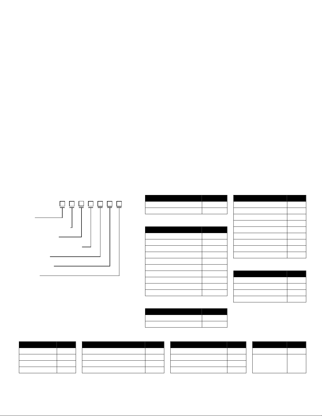
MODEL DESCRIPTION
Model
Process Connection
Sensor Material
Insertion Length (Inches)
Input Power
Configuration
- - - - - -
Options
Description Code Description Code Description Code Description Code
No Options 00 Extended Neck EN Additional Cable CA SS Tag TG
RTD Output RT *High Temp (850ºF) HT Variable Insertion VI
Live Tap LT *Medium Temp (572ºF) MT Factory Calibration CB
CE Approved CE Explosion-proof Window XW Thermocouple Output TO
* Remote Mounting Required
Description Code Description Code
Level Switch KTDL 316L SS S6
Flow Switch KTDF 304 SS S4
304L SS SL
Process Connection
Hastelloy-B HB
Description Code Hastelloy-C HC
½” NPT 050 Inconel 600 IO
¾” NPT 075 Monel MN
1” NPT 100 Alloy-20 A2
1½” Sanitary 3A1 Special Material SM
1” 150# ANSI Flange RA1
2” 150# ANSI Flange RA2
Input Power
1” 300# ANSI Flange RB1 Description Code
2” 300# ANSI Flange RB2 110 Vac 110
Low Flow Sensor LFS 220 Vac 220
Special Connection SPL 24 Vdc 24D
Configuration
Description Code
24 Vac 24A
Insertion Length
Integral Mounting LE 002.00 (standard)
Remote Mounting RE 000.50 – 120.00 (optional)
Sensor
Installed in
TE
Tee
Page 2
Page 3
INSTALLATION
Unpack the switch carefully. Inspect all units for damage. Report any damage to carrier immediately. Check the
contents against the packing slip and purchase order.
Kenco’s Thermal Differential Flow / Level Switches are manufactured to the highest quality standards. These instruments
use electronic components that can be damaged by static electricity. Make sure that you are properly grounded before
starting installation. Insure that all electrical connections are properly made, and that there are no “floating” connections.
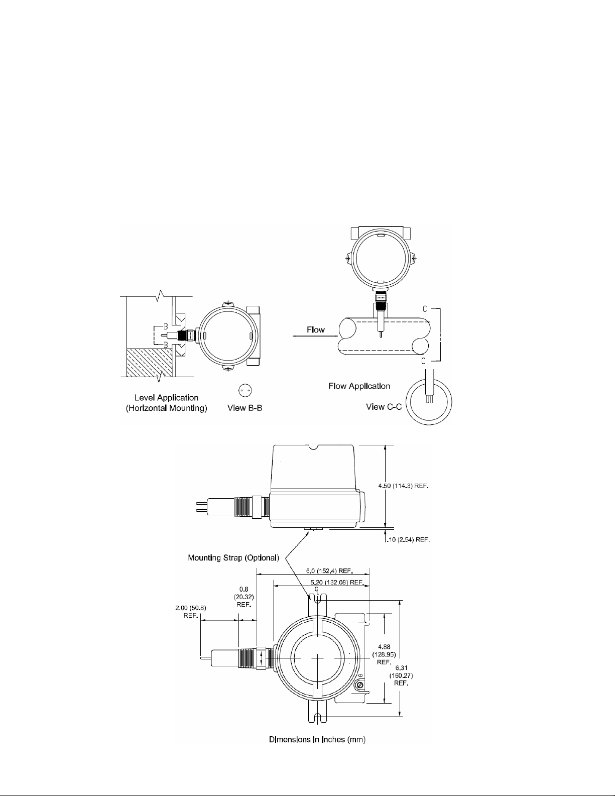
Mechanical Installation
The Series KTD Switches have a ¾” NPT (standard) process connection. When used as a level / interface switch, and
horizontally mounted, the sensor must be oriented so that the RTD’s are parallel with the liquid surface. When used as a
flow switch the sensor must be oriented so that the RTD’s are perpendicular with the flow direction.
Use a 1-1/8” open end wrench to tighten the sensor in the process connection. Use the hex flats on the sensor for
tightening. DO NOT use the instrument housing for tightening. Rotation of the instrument housing in respect to the
sensor can cause internal wiring damage, and will void the warranty.
Page 3
Page 4

Electrical Installation
Field Wiring (TBB)
It is recommended that conduit be installed onto the ¾” NPT connection on the electronics housing. A seal drain fitting
should be used to prevent moisture from entering the switch. In high humidity areas, use a breather drain to minimize
moisture intrusion
All wiring, conduit, and fittings must conform to local electrical codes for the location selected. If the transmitter is to be
used in a Hazardous Area, the applicable sections of the National Electric Code must be followed as well.
WIRING CONNECTIONS
Before starting installation procedures in hazardous areas, insure that all power sources have been turned off and locked
out. “Live” electrical circuits can ignite flammable gasses and dusts.
1. Remove the cover from the instrument enclosure.
2. Loosen the (2) screws holding the electronics module in place. These are spring-loaded captive screws. They
will pop-up when loosened sufficiently. Remove the electronics module from the instrument enclosure.
3. Hold the module firmly around the transformer and pull it out of the enclosure. No tools are necessary to remove
the module.
Sensor Wiring (TBA)
Page 4
Page 5

4. Pull the power/signal wires through the conduit opening.
5. Connect Power and relay wiring to Terminal Block (TBB) see figure on previous page.
6. Reinstall the Electronic Module and tighten the (2) captive screws.
7. Reinstall the Instrument Enclosure cover.
OPERATIONAL CHECK
After the switch is installed, and the level is below the sensor or there is no flow, perform the following test procedure to
insure proper function.
1. Remove the Instrument Enclosure Cover.
2. Apply power.
3. Verify that either the Red or Green LED is illuminated.
4. If neither LED is on, refer to the Troubleshooting section.
PRE-CALIBRATION
LED States
The Red and Green LED’s indicate the status of the sensor, and are independent of the relay status. When the Red LED
is illuminated, this indicates a Dry (Level) or No/Low (Flow) condition. When the Green LED is illuminated, a Wet (Level)
or High (Flow) condition is indicated.
Jumper Settings
There are (2) jumpers that must be set prior to calibration:
J1 – Model KTDL – There is no J1 Jumper or Pins
Model KTDF – Leave the Jumper in place for Flow Applications; Remove the Jumper if you decide to use this
model for a Level / Interface Application
Page 5
Page 6

J2 – This sets the Failsafe condition of the switch. The jumper should cover the (2) left-most pins for High Level
J2 J2
Failsafe (HLFS) condition, or the (2) right-most pins for Low Level Failsafe (LLFS) condition. See the table
below for the comparison of the two conditions, as well as the condition of the Red and Green LED’s.
HLFS LLFS
Status
or High Flow
or Low/No Flow
Red
LED
Off On
On Off
Green
LED
Fail Safe
Setting
Relay
Condition
HLFS De-Energized Closed Open Wet (Level)
LLFS Energized Open Closed
HLFS Energized Open Closed Dry (Level)
LLFS De-Energized Closed Open
Relay Terminals Sensor
NC to C NO to C
CALIBRATION (Level Switch)
(Refer to Page #5 for location of controls)
NOTE: For optimum performance, the calibration must be done at actual process temperature.
1. Remove the Instrument Enclosure Cover
2. Ensure that the level is below the
sensor tips, and that the tips are
dry.
3. Apply power. Allow the sensor
to warm-up for five minutes.
4. Set the “Trip Point Adjust” pot to
“0” (fully counterclockwise).
5. Set the “Zero Adjust” pot so that
the Red LED just does
illuminate. This is a 25-turn pot.
If the Green LED is on, turn the
pot counterclockwise. If the Red
LED is on, turn the pot
clockwise.
6. Toggle the “Zero Adjust” pot
back and forth until the trip point
is well defined. Leave the Red
LED Illuminated.
7. Raise the level of the liquid in the
vessel until the sensor tips are
covered.
8. Set the “Trip Adjust” pot to 100
(fully clockwise).
9. Set the “Span Adjust” pot so that the Green LED just does illuminate. This is a 25-turn pot. If the Green LED is on,
turn the pot clockwise. If the Red Led is on, turn the pot counter clockwise.
10. Toggle the “Span Adjust” pot back and forth until the switching point is well defined. Leave the Green Led illuminated.
11. Set the “Trip Point Adjust” pot to 80 and the calibration is complete. Setting this pot to 80 gives an approximate equal
trip time from wet-to-dry and dry-to-wet. Setting this pot closer to “0” will speed up the dry-to-wet time, and slow down
the wet-to-dry time. Setting this pot closer to “100” will slow down the dry-to-wet time, and speed up the wet-to dry
time.
Page 6
Page 7
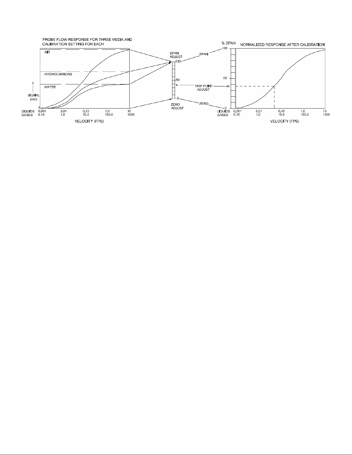
CALIBRATION (Flow Switch)
(Refer to Page #5 for location of controls)
NOTE: For optimum performance, the calibration must be done at actual process temperature and pressure
conditions in gasses, or actual process temperature in liquids.
NOTE: The sensor tips must be perpendicular to the flow direction (see Page #3 – View C-C)
1. Remove the Instrument Enclosure Cover
2. Ensure that the pipeline is filled with fluid and at no or minimum flow.
3. Apply power. Allow the sensor to warm-up for five minutes.
4. Set the “Trip Point Adjust” pot to “0” (fully counterclockwise).
5. Set the “Zero Adjust” pot so that the Red LED just does illuminate. This is a 25-turn pot. If the Green LED is on, turn
the pot counterclockwise. If the Red LED is on, turn the pot clockwise.
6. Toggle the “Zero Adjust” pot back and forth until the trip point is well defined. Leave the Red LED Illuminated.
7. Adjust the liquid or gas flow to maximum velocity for the application. Insure that the flow is homogenous, constant,
and if a liquid – free of bubbles. NOTE: The maximum allowable flow rate for the unit is 2.5ft/sec (aqueous
liquid), 5 ft./sec (hydrocarbon liquid) or 500ft./sec (gases).
8. Set the “Trip Adjust” pot to 100 (fully clockwise).
9. Set the “Span Adjust” pot so that the Green LED just does illuminate. This is a 25-turn pot. If the Green LED is on,
turn the pot clockwise. If the Red Led is on, turn the pot counter clockwise.
10. Toggle the “Span Adjust” pot back and forth until the switching point is well defined. Leave the Green Led illuminated.
11. If the switch is to be used for flow – no flow, set the “Trip Adjust” pot to 50 and go to Step #14. NOTE: This
adjustment can be set for tripping points between 10% and 90% of the span from no flow to maximum flow).
12. A more exact flow rate setting may be made by establishing the flow at the desired rate with a separate flow meter
and proceeding to Step #13.
13. Adjust the “Trip Adjust” pot to obtain a trip point as exhibited by the LED Status Lights. If trip on decreasing flow is
desired, set for Red Illumination. If a trip on decreasing flow is desired, set for Green Illumination.
14. Verify that the switch will reset by returning the actual product flow to maximum or minimum flow rates. The
calibration is complete.
Page 7
Page 8

MAINTENANCE & TROUBLESHOOTING
The sensor can be cleaned by soaking, spraying or ultrasonic cleaning. Verify material compatibility before using any
strong solvent or acid on the sensor. DO NOT sandblast or scour the sensor with abrasives. The sensor could be
damaged by this process.
TEST #1 - Power & Continuity Check
1. Remove power.
2. Remove Instrument Enclosure cover.
3. Loosen (2) Captive Screws (see Page #4)
4. Remove Electronic Module by grasping the Transformer, and pulling straight out.
5. Apply power. Verify the correct voltage at pins 7 (+ for DC) & 8 (- for DC) of Terminal Block TBB.
6. If the voltage is correct, remove power and check the fuse (F1 – see Page #5). If the fuse is bad, replace it with the
appropriate fuse.
7. If the fuse is OK, proceed to the Functionality Check.
TEST #2 - Functionality Check (Perform TEST #1 first)
1. Remove power.
2. Allow a 5 minute cool-down period.
3. Measure the resistance of each RTD (Terminal Block TBA).
a. Measure the resistance between Pins 1 & 6 – (First RTD).
b. Measure the resistance between Pins 3 & 5 – (Second RTD).
4. The resistance values for Step #3 should be 110Ω ± 10Ω @ 70ºF. Also, they must be within 5% of each other.
5. Measure the resistance between Pin #1 of Terminal Block TBA and the Instrument Enclosure. It should be greater
than 20Meg Ohms.
6. If the resistance values are not as specified above, the sensor must be replaced.
7. If the resistance values are correct, the Electronics Module must be replaced.
SPECIFICATIONS
Description Specification
Power Supply
Output 5A DPDT – Failsafe is field selectable
Temperature Range
(Electronics)
Temperature Range
(Sensor)
Pressure Range Atmospheric to 3000psig
Operating Range (Flow)
Response Time 0.5 to 5.0 seconds (media dependent)
Stability <0.5% from calibrated setpoint over a range of ±50ºF
Repeatability ±1.0%
AC 110Vac or 220Vac @ 50/60 Hz
DC 24Vdc
-40ºF to 140ºF (-40ºC to 60ºC)
Standard -100ºF to 390ºF (-70ºC to 200ºC)
Medium Temp. -100ºF to 572ºF (-40ºC to 300ºC)
High Temp. -100ºF to 850ºF (-40ºC to 458ºC)
Aqueous Liquids 0.01 – 2.5 feet/second
Hydrocarbon Liquids 0.01 – 5.0 feet/second
Gasses 0.1 – 500 feet/second
Page 8
 Loading...