

Page 1

KENCO ENGINEERING COMPANY
P.O. BOX 470426 TULSA, OK 74147-0426 ● PHONE: (918) 663-4406 FAX: (918) 663-4480
www.kenco-eng.com e-mail: info@kenco-eng.com
SMARTSONIC REMOTE ACOUSTIC WAVE LEVEL / OPEN CHANNEL FLOW TRANSMITTER
INSTALLATION / OPERATION INSTRUCTIONS
TABLE OF CONTENTS
1. GENERAL DESCRIPTION ............................................................. 2
2. PRINCIPLE OF OPERATION ......................................................... 2
3. MODEL DESCRIPTION .................................................................. 2
4. SPECIFICATIONS .......................................................................... 2
5. INSTALLATION .............................................................................. 2
6. DIMENSIONS.................................................................................. 3
7. MOUNTING GUIDELINES .............................................................. 4
8. MOUNTING INSTRUCTIONS ......................................................... 4
9. WIRING ........................................................................................... 5
Wiring Connections....................................................................... 6
10. CALIBRATION................................................................................ 8
Accessing the Main Menu............................................................. 10
11. SETTING THE MAIN MENU OPTIONS .......................................... 11
12. OPEN CHANNEL FLOW MEASUREMENT ................................... 22
13. ADDITIONAL FEATURES .............................................................. 30
Additional Features Program List................................................ 31
14. TROUBLESHOOTING .................................................................... 37
Page 1
Page 2
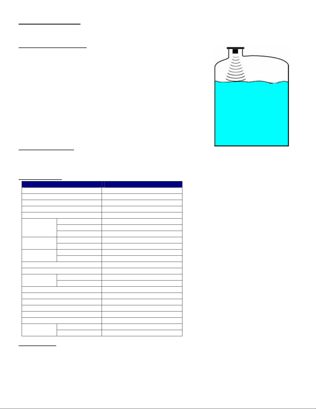
GENERAL DESCRIPTION
Process
Media
Air
Acoustic
The SmartSonic Acoustic Wave Transmitter is designed for high accuracy level measurement of a variety of liquids. The
SmartSonic Integral can also be used for Open Channel Flow Measurement.
PRINCIPLE OF OPERATION
The SmartSonic Transmitters consist of two main components:
• The Electronics
• The Sensor (Transducer)
The transducer contains a piezoelectric crystal that converts an electrical signal
from the electronics, into acoustic (sound) waves. These acoustic waves are
directed through the air toward the process media surface. They are then
reflected off of this surface and returned to the transducer. The piezoelectric
crystal then converts the received waves into an electrical signal which is
analyzed by the electronics.
The time difference between the transmitted wave and the received wave is
proportional to the distance from the face of the transducer to the process media
surface. This distance is used by the electronics to calculate level or open
channel flow in the units selected by the operator.
Waves
MODEL DESCRIPTION
P50-L35V-6N8AE - Remote Transmitter KAWT-xx – Remote Cable (xx = Length in Feet)
PN5-XGB-1-C – 1” NPT Polypropylene Transducer ACC-I – Remote Cable Connector
PN5-XGD-1-C – 1” NPT PVDF (Kynar) Transducer
SPECIFICATIONS
Description Specification
Power Supply 100-230 Vac
Maximum Range 39.4 feet
Minimum Dead Zone 1.3 feet
Maximum Span 38.1 feet
Frequency 50 kHz
Output
Signal
Ratings
Interface
Wave Angle 5º @ 3db
Mounting Connection 1” NPT
Range
Accuracy ±0.2% of max. range
Resolution 0.04” (1 mm)
Enclosure Material ABS + UV
Transducer Housing Material Polypropylene or PVDF
Transducer Material Glass Reinforced Epoxy
Cable Length 328ft. (std.); 656ft. (opt.)
Weight
INSTALLATION
Unpack the transmitter carefully. Inspect all units for damage. Report any damage to carrier immediately. Check the
contents against the packing slip and purchase order. Kenco’s SmartSonic Acoustic Wave Transmitters are
manufactured to the highest quality standards. These instruments use electronic components that can be damaged by
static electricity. Make sure that you are properly grounded before starting installation. Insure that all electrical
connections are properly made, and that there are no “floating” connections.
Analog 4-20mA
Digital RS-422
Discrete (5) SPDT Relays
AC 2A @ 220Vac Relay
DC 2A @ 30Vdc
Display Graphical LCD User
Keypad 4 Button
Ambient -40ºF to 140ºF Temperature
Process -40ºF to 212ºF
Electronics 2.4 lbs
Sensor 1.1 lbs.
Page 2
Page 3
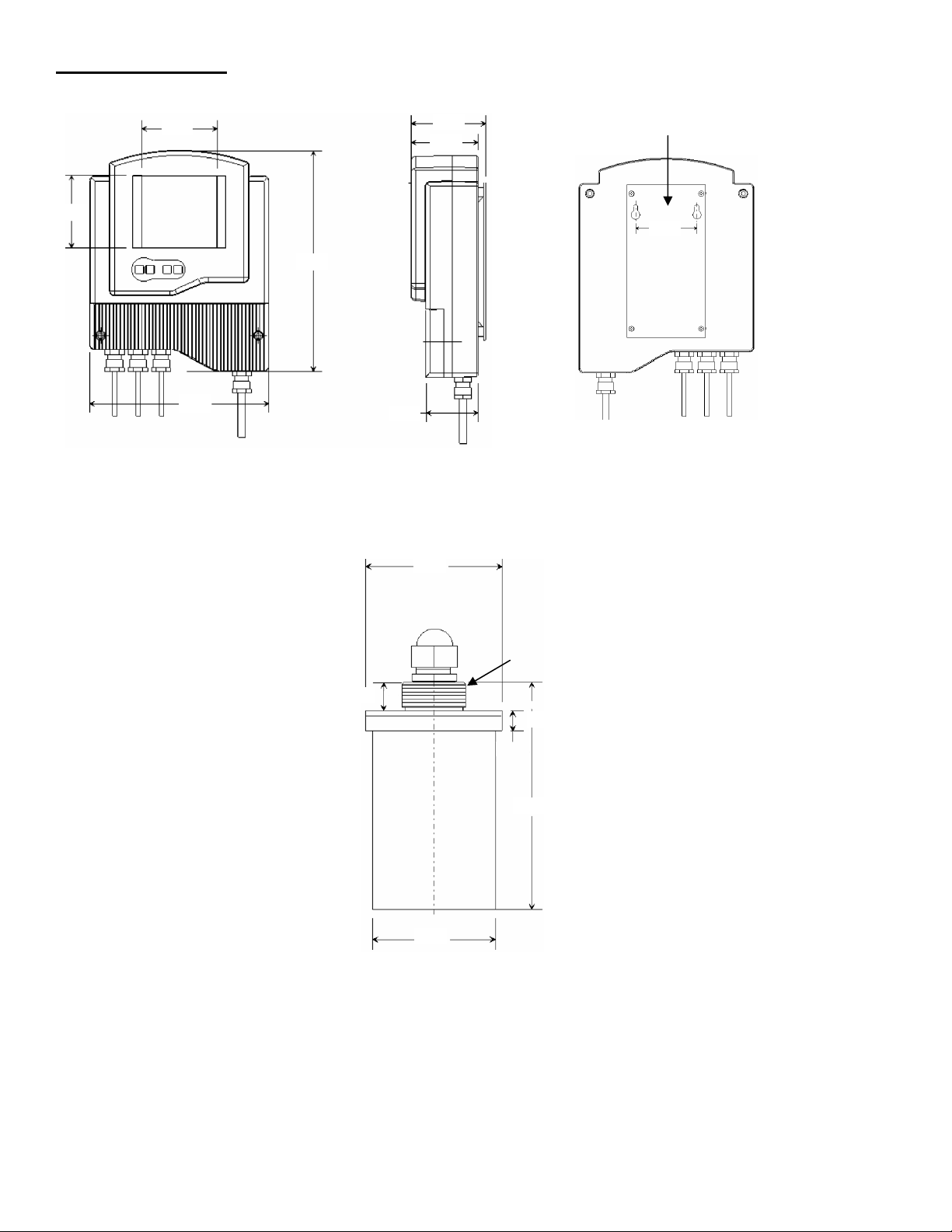
DIMENSIONS - INCHES
3.15
3.31
9.68
3.26
2.87
2.28
2.75
Transducer
(Sensor)
2.83
0.59
4.88
2.56
0.55
1” NPT
7.87
Mounting Plate
Page 3
Page 4
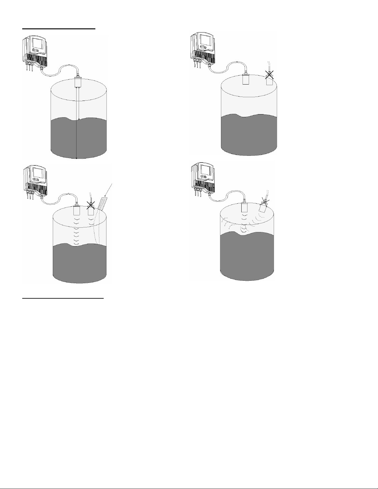
MOUNTING GUIDELINES
MOUNTING INSTRUCTIONS
Precautions:
• Ensure that the sensor is mounted in an area that meets the stated temperature, pressure and technical
specifications.
The transmitter must
be mounted in such a
way, as to avoid the
process fluid level from
entering the Dead
Zone.
If the level enters the
Dead Zone, an error
will occur, and the
transmitter will not
measure the fluid level
The sensor needs to
be mounted as far
away as possible from
processes that can
interfere with the
Acoustic Wave. This
example shows a fluid
filling inlet.
While the narrow wave
diameter of the Kenco
Acoustic Wave
Transmitters allows
you to mount the
sensor closer to the
vessel wall, than other
Ultrasonic transmitters,
it is recommended to
mount the sensor at
least 1.64 feet away
from the wall.
The sensor must be
mounted perpendicular
with the process fluid
level. Even the
slightest mounting off
perpendicular will affect
the measurement.
Anything over 4º will
usually result in a loss
of echo or at the very
least, an inaccurate
reading
• Ensure that high voltage (ac) sources or cables are at least 1 yard away from the sensor and its cable.
• Installation and Operation of this transmitter must conform to the National Electric Code and any applicable local
codes.
Direct Mounting of the Sensor to the Tank
1.) Open the top of the tank
2.) Feed the free end of the sensor cable from the inside of the tank, through the 1” NPT coupling attached to the top
of the tank (customer supplied).
3.) Keep feeding the cable until the sensor threads are touching the coupling. Screw the sensor threads into the
coupling.
Page 4
Page 5
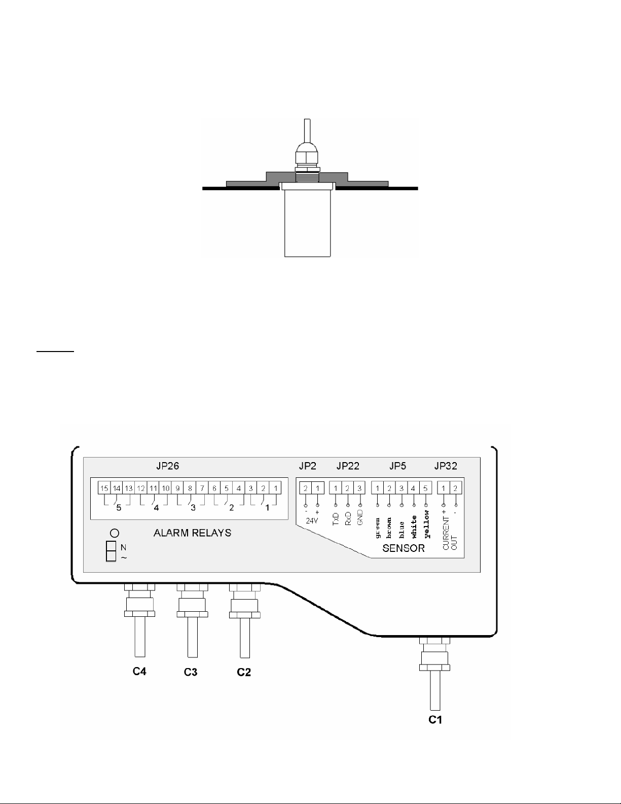
Mounting the Sensor to a Flange
2
1
JP1
1.) Feed the free end of the sensor cable through the 1” NPT threaded connection on the flange. Feed the cable from
the process side of the flange
2.) Keep feeding the cable until the sensor threads are touching the inside of the flange. Screw the sensor threads into
the 1” NPT threaded connection on the flange.
3.) Bolt the flange to the top of the tank. Use a soft gasket.
Mounting the Transmitter (Electronics)
1.) Drill (2) holes, 2.75” apart, onto the desired mounting surface. Install (2) screws into these holes.
2.) Attach the mounting plate to the SmartSonic, using the (4) screws provided.
3.) Mount the SmartSonic onto the desired mounting surface, using the slotted holes on the mounting plate and the (2)
screws on the desired mounting surface from Step #1.
WIRING
It is recommended that conduit be installed onto the ½” NPT connections (C1 thru C4) on the electronics
housing. Seal drain fittings should be used to prevent moisture from entering the transmitter. In high humidity
areas, use breather drains to minimize moisture intrusion.
All wiring, conduit, and fittings must conform to local electrical codes for the location selected. If the transmitter is to be
used in a Hazardous Area, the applicable sections of the National Electric Code must be followed as well.
GND
Page 5
Page 6
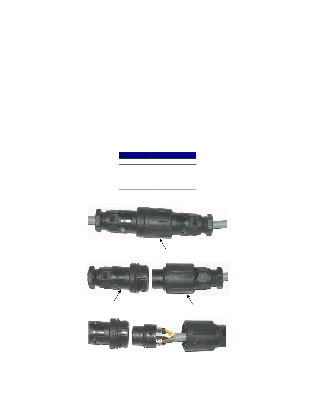
Sensor cable side
Wiring Connections
In order to connect the wiring, remove the ribbed faceplate on the front of the electronics, using a 7/64” (3mm) Allen
wrench. Ensure that the cover is reinstalled, with the gasket in place, after completing the wiring. Refer to the drawing on
the previous page for the location of the wiring connections and cable entries.
NOTE: Power must be off when wiring the electronics. Damage and/or injury may occur if power is applied
during wiring.
Wiring the Sensor Connections
The sensor uses a custom 5-conductor cable between the sensor and electronics. The cable comes with a cable
connector, which can be used to extend the length of the cable. Make sure that you use Helukabel p/n 16028. Use of
any other cable may damage the sensor, or interfere with the signal.
If you are only using the standard 16.4 ft. of cable supplied attached to the sensor, or the non-connector end of an
extended cable:
1.) Remove the cable connector from the sensor-side of the cable (the male plug). Skip this step if you are using the
non-connector end of an extended cable.
2.) Thread the cable through aperture (C1 – see wiring drawing on page 5) located on the right side of the SmartSonic
electronics base.
3.) Connect each wire by color, to the appropriate screw terminal on connector JP5. If the cable contains multiple black
wires, connect as follows:
JP5 Post Color
1 Green (Black 1)
2 Brown (Black 2)
3 Blue (Shield)
4 White (Black 3)
5 Yellow
If you are using the cable connector, follow these directions:
Nut
1.) Unscrew the nut holding the cable connector together.
Loose cable side
2.) Disassemble the “loose cable side” of the connector.
3.) Disconnect the “dummy cable” wires from the connector, and connect the wires from the extended cable (supplied
separately). The blue wire is connected to the cable shield. Make sure that the wires match exactly. If you aren’t
sure, disassemble the “Sensor cable side” connector and match up the pins to the wire color. If you have any
questions, please contact Kenco. Do not apply power unless the connector is wired correctly.
Page 6
Page 7
Wiring the Digital and Analog Communication Cables
SmartSonic data can be monitored on a PC or PLC via RS-485 (MODBUS RTU) digital communications, when connected
to JP22. You can also monitor a 4-20mA output by connecting to JP32 (the 4mA and 20mA settings are discussed in the
CALIBRATION section).
1.) Thread the connection wires through aperture C2.
2.) Connect each wire to the appropriate screw terminal at connection block JP22 (MODBUS) and / or JP32 (4-20mA).
JP22 connections are as follows:
JP22 Post Wire
1 B (TxD)
2 A (RxD)
3 Ground
JP32 connections are as follows: Post 1 (+); Post 2 (-).
JP32 Post Wire
1 +
2 -
Wiring the Power Connections
1.) Thread the power wires through aperture C4
2.) If you have 100-230Vac power, connect each wire to the appropriate screw terminal on JP1 as follows:
JP1 Post Wire
1 Neutral
2 Hot
GND Ground
NOTE: If you are using 100-230Vac leave the red and black wires connected to JP2.
3.) If you have a 24Vdc power source, disconnect the red and black wires from JP2, and connect your power wires:
JP2 Post Wire
1 +
2 -
NOTE: Use either JP1 or JP2. Do not connect external power to both.
Wiring the Relays
1.) Thread the power wires through aperture C2 (DC Power) or C4 (AC Power). C3 may not be available when using
conduit.
2.) Connect each wire to the appropriate screw terminal (see wiring drawing on page 5).
Page 7
Page 8
CALIBRATION
This section explains how to set up and calibrate the SmartSonic for accurate measurement monitoring using the basic
menu options. SmartSonic is supplied with preprogrammed default settings, making it ready for immediate operation.
Measurement readings are displayed on the default screen as soon as the unit is powered on. It is recommended that
you replace the default tank height value with the actual tank height, as described later in this section.
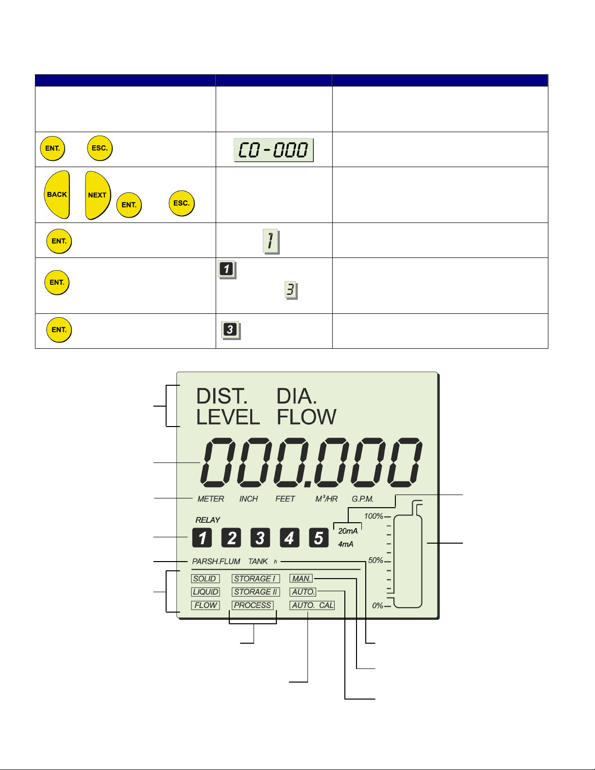
Display / Keypad
The LCD display screen functioning in “Normal” mode provides continuously updated measurement readings. This
display is also used to view the program menus, options, settings, and data values. These are accessed by using the
keypad. The picture below shows the display of the SmartSonic:
The keypad buttons are used to perform various operations, summarized in the following table
Indication modes
Numerical area
Measurement
units
Relays
Flow
measurements
Application types
Button Uses Include:
or
20 mA/4 mA
levels
Tank graphic
Operation
modes
Scan distance
Tank height
Sensor offset
mode indicator
Clear scan distance
• Accessing the program menu (when pressed simultaneously with “ESC.”
• Accessing a function within a menu, enabling you to make modifications
• Moving from left to right between displayed digits.
• Saving changes to data.
• Accessing the program menu (when pressed simultaneously with “ENT.”
• Moving from right to left between displayed digits.
• Returns you to the previous function (without saving changes), or back to
the default screen
• Moving to the next/previous function within a menu.
• Scrolling through or back data values in programs.
NOTE: Within some programs, the digits in the display can be individually modified. This is indicated by a flashing digit.
In this case the ENT and ESC buttons are used to move between digits. The BACK and NEXT buttons are used to
change the value of the flashing digit.
Page 8
Page 9
Tank Terminology
Process
Media
r
Tank
Span
Dead Zone
Ai
Dead Zone
SmartSonic Remote
● Minimum 1.3 feet
Tank Height
SmartSonic Remote
● Maximum 39.4 feet
Height
Span Range
(4mA to 20mA)
SmartSonic Remote
● Maximum 38.1 feet
Default Screen
As soon as SmartSonic is fully installed and powered on, the LCD displays the default screen. The default screen
provides continuously updated measurement readings and displays the current settings for some functions (either the
default settings or the settings selected from the main menu). The relay number is displayed for each activated relay. You
can toggle between display indication types, such as: level, distance, volume and others, by using the SmartScan Main
Menu.
The tank graphic in the default screen gives an approximate visual indication of the current level of the tank contents,
while the numerical area gives the exact reading. If the level enters the dead zone, the numerical area displays FF FFF. If
the tank is empty, the numerical area displays the tank height. 000000 may be displayed temporarily while SmartSonic is
taking a reading. You can refresh the reading by pressing the ENT and BACK buttons simultaneously.
NOTE: By default, the displayed value is in meters, and gives the distance measurement, meaning from the sensor face
to the level of the fluid. The measurement indication mode and measurement unit can be changed, as described in Setting
Main Menu Options
Page 9
Page 10
Accessing the Main Menu
and
This section describes the procedure for accessing the SmartSonic Main Menu. The main screen (see Page #7) is
accessed as follows:
Press / Action Display Description
The SmartSonic takes several seconds to
Connect SmartSonic to power supply See Wiring Section
and simultaneously
Flashes for 5
Flashes for 5
seconds, then is
displayed
seconds
warm-up. During this time various characters
will turn on and off, and the Tank Graphic will
cycle
This is the password display
Use to enter the password (716) in place of
(000). BACK and NEXT will change the vlue of
the digit (0-9). ENT steps to the next digit; ESC
steps to the previous digit.
Single Sensor (only available option).
Press ENT.
The main screen (Page #7) is now displayed.
Main Screen Functions
Indication modes
Numerical area
Measurement
units
Relays
Flow
measurements
Application types
20 mA/4 mA
levels
Tank graphic
Operation
modes
Scan distance
mode indicator
Tank height
Sensor offset
Clear scan distance
Page 10
Page 11
SETTING MAIN MENU OPTIONS
The following functions are available in the SmartSonic Main Menu:
Functions Page
Setting the Indication Mode 11
Setting the Measurement Units 12
Setting the Relay Values 12
Setting The 20mA and 4mA Values 17
Setting the Open Channel Flow Measurements 17
Setting the Tank Height 17
Setting the Application Type 18
Setting the Operation Modes 18
Setting the Sensor Offset 19
Setting the Scan Distance Values 20
Clearing the Scan Distance Values 21
NOTES: After you select any option the “Tank Graphic” will cycle a few times. Wait until one of the
options starts to blink before proceeding to the next step.
When you change an option, a flashing “Ar. 5” may appear. This is just to remind you that the option
you just selected may affect the Relay or 4-20mA Settings, and that you need to review these settings.
Setting the Indication Mode
The first function in the Main Menu is the Indication Mode. This sets the type of measurement. The options are:
• DIST: The displayed reading represents the distance from the sensor face to the process media.
• LEVEL: The displayed reading represents the level of the process media measured from the bottom of the vessel.
• FLOW: The displayed reading represents the flow rate through the configured Flume or Weir.
• DIA: DO NOT USE
Setting an Indication Mode enables you to toggle between other indication types as well, using the BACK and NEXT
buttons as described in the table below: For example, if the unit is configured for Level, the BACK and NEXT buttons will
toggle between Level and Distance.
Indication Toggle Selections (BACK / NEXT Buttons)
Distance Distance / Level
Level Level / Distance
Flow Flow / Level / Distance / Totalization (High) / Totalization (Low)
Totalization indicates the total accumulative flow. It is expressed in 10 digits. The first 5 digits (High) are shown as
H00000, and the second 5 digits (Low) are shown as L00000. This function will be described later in this manual
(Additional Features).
Press / Action Display Description
and
Move between the available options. DIA
(Diameter) is no longer available.
For Example
Select the desired option. This will show on the
display for a few moments, then return to the
Main Menu
Go to the next function (Measurement Mode)
Page 11
Page 12
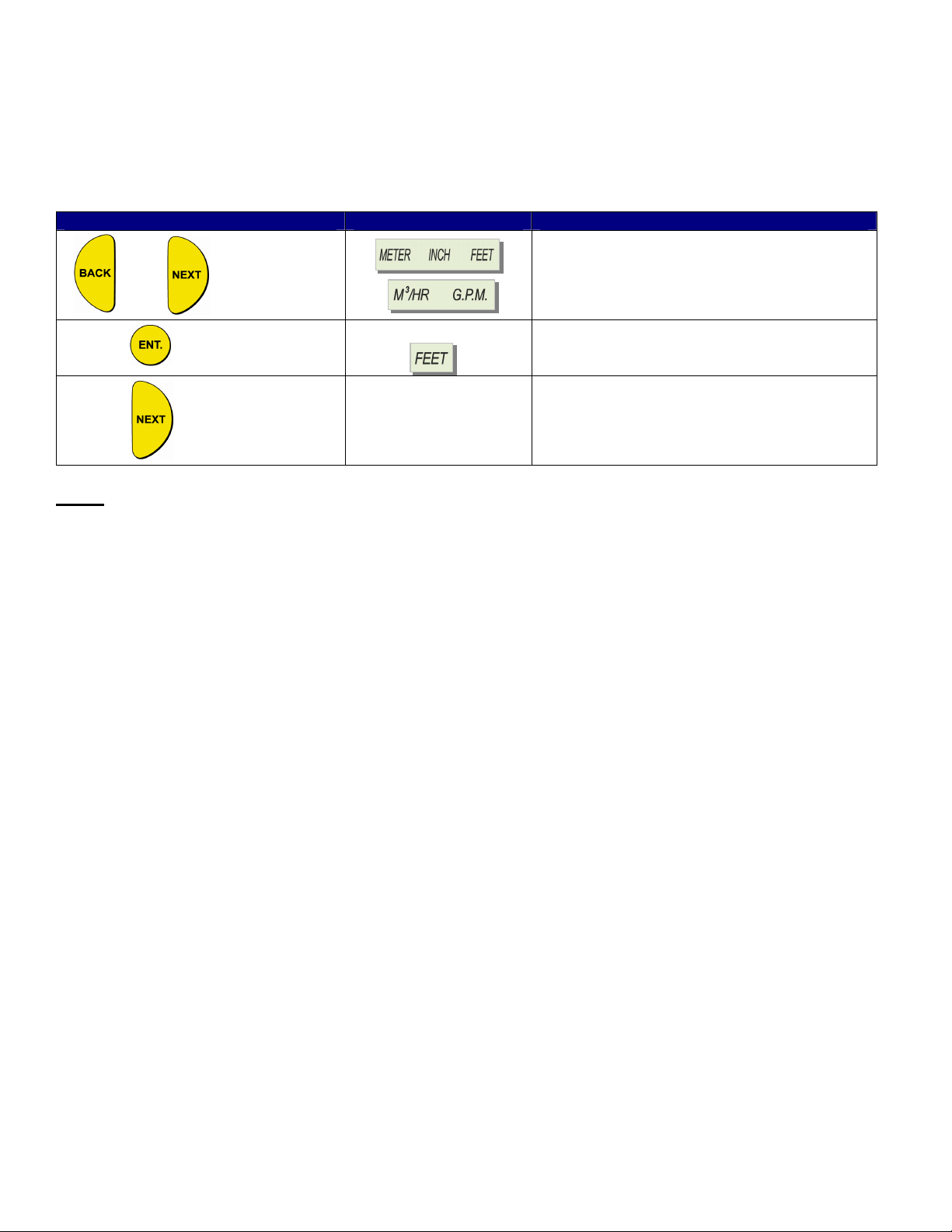
Setting the Measurement Mode
This function is used to select the units used for the display. The following measurement options are available:
• METER (default), INCH, or FEET: Select one of these options for Level or Distance measurements
• M3/HR or G.P.M.: Select one of these for Flow measurements
After setting the measurement unit, the selected unit flashes on the display whenever you enter numerical values during
the setup procedure. The values for functions, such as Relay, will be displayed in the selected measurement unit.
Press / Action Display Description
Move between the available options.
and
For Example
Select the desired option. This will show on the
display for a few moments, then return to the
Main Menu
Go to the next function (Relay Values)
NOTE: If you select METER any relevant flow measurement will be in metric units (M3/HR). The opposite also applies,
so that if you select M3/HR, any relevant distance or level measurements will be in meters. If you select INCH or FEET,
the flow measurements will be in G.P.M.. If you select G.P.M., any relevant distance or level measurements will be in
inches.
If you select METER when using a FLOW unit configured to show G.P.M., the METER sign will flash rapidly for a few
seconds. If you approve the selection by pressing ENT, the flow unit will change to M3/HR.
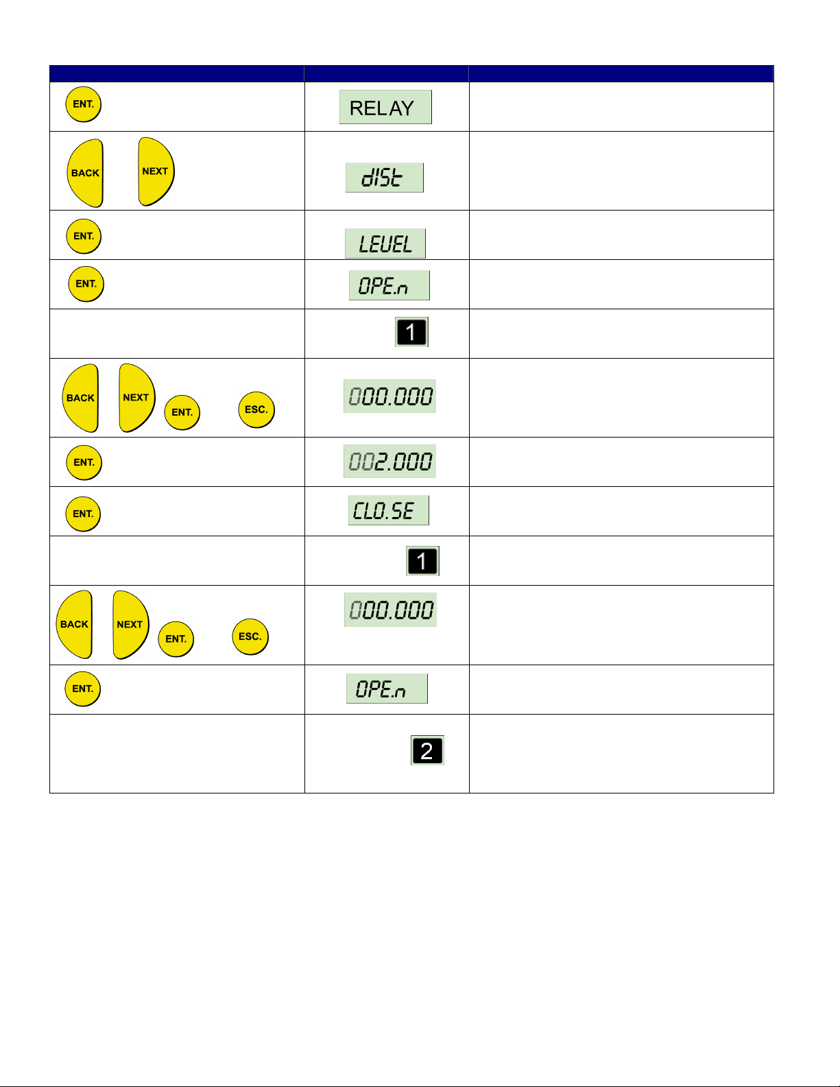
Setting the Relay Values
The relays in the SmartSonic Remote are SPDT (Single Pole, Double-throw). This means that each relay has (3)
connections:
• Normally Closed (NC)
• Common (C)
• Normally Open (NO)
In the SmartSonic, the term CLOSED means that the relay is de-energized. In this state the NC and C terminals are
closed (connected), and the NO and C terminals are open (disconnected).
The term OPEN means that the relay is energized. In this state the NC and C terminals are open (disconnected), and the
NO and C terminals are closed (connected).
In the event of power loss to the SmartSonic, the relays automatically go to the CLOSED state (NC & C are connected;
NO & C are disconnected). Make sure that any auxiliary equipment connected to the SmartSonic relays, will be in a safe
condition upon loss of power to the SmartSonic.
You can set the relays to (5) different indication modes:
• Level
• Distance
• Flow
• Volume
• Totalization
Page 12
Page 13

Volume and Totalization should only be configured after setting the Volume/Totalization options in the Additional Features
Section later in this manual. The following are the relay setup options:
Indication Mode Relay Mode
Distance Distance / Level
Level Level / Distance
Volume Volume
Flow Flow / Distance / Level
Totalization Flow / Totalization
For example, if the SmartSonic is set to FLOW Indication Mode, the relay can be set to Flow, Distance or Level values.
Each of the (5) relays in the SmartSonic allows you to define OPEN and CLOSED values, enabling its use for functions
such as triggering an alarm or controlling pumps. As an alternate, Relay #4 can be configured to report error messages,
and Relay #5 can be configured for a Flow Totalization pulse (see instructions later in this section).
The relay values function as follows:
• OPEN: The relay energizes if the level measured in the vessel is higher than the programmed OPEN value.
• CLOSED: The relay de-energizes if the level measured in the vessel is lower than the programmed CLOSED
value.
The default value for the OPEN and CLOSED functions is 0. The indication mode default value is LEVEL.
NOTE: The CLOSE value must be at lease 1 inch lower than the OPEN value. An error (Err. 3 or Err. 10) will appear if
this is not the case. If a relay value greater than the tank height is entered error (Err. 7) will appear
Page 13
Page 14
and
mode
Press / Action Display Description
Press ENT when “Relay” is flashing to enter
relay setup
or
For Example:
For example:
and
Cycle between Level, Distance, Flow (see next
table), Volume, Totalization (Relay #5 only).
Press ENT to select the desired option
Press ENT to enter the OPEN function
The appropriate relay number flashes
throughout the process of defining the values
for the relay
Select the desired value for the OPEN
condition of this relay
Enter the value from the previous step
Press ENT to enter the CLOSED function
and
Relay values can be configured with an alternate method when set to Flow, Volume or Totalization modes (see Additional
Features Section for information on Volume or Totalization Modes).
Use the following procedure to set the relay values for FLOW:
and
and
The appropriate relay number flashes
throughout the process of defining the values
for the relay
Select the desired value for the CLOSED
condition of this relay. Must be 1 inch (3cm)
less than the OPEN Value.
Press ENT to enter the OPEN function
Repeat the previous steps to set an OPEN and
CLOSED value for each relay to be used. If
you do not want to set a value for every relay,
use the ESC button to exit the relay setup
Page 14
Page 15

Press / Action Display Description
Press ENT when “Relay” is flashing to enter
relay setup
or
or then
and
and
For example:
and
Cycle between options until it displays FLOW
Press ENT to select the FLOW option
Select the relay number you wish to configure,
then press ENT.
The appropriate relay number (Relay #1 in this
example), flashes throughout the process of
defining the values for the relay
This screen allows you to enter up to (4) digits
of High numbers of flow values.
This screen allows you to enter up to (5) digits
of Low numbers of flow values.
In the example above, the relay values were configured in the following way:
• 00001 was entered in the High numbers (H = 1)
• 20000 was entered in the Low numbers (L = 20,000)
This would mean that the OPEN value was set at 120.000 (G.P.M. or M3/HR)
NOTE: The same procedure is used for the Volume and Totalization Modes. The units for the Totalization Mode are
Gallons when the selected Measurement Unit is G.P.M. The units for the Volume Mode are the same used when entering
the Volume Strapping Table (see Additional Features Section later in this manual).
Setting Relay #4 to Report Errors
This allows you to use Relay #4 as a trigger to set an alarm if the unit has a “Lost Echo”, indicates a level higher than the
Tank Height, or when the level moves into the “Dead Zone”. Once the error mode is enabled, and an error occurs, the
relay will de-energize and the error message will show on the display. The following are the error displays:
• EE EEE: Loss of Echo, or measurement value is greater than the Tank Height.
• FF FFF: Process media is in the “Dead Zone”.
The relay will be energized as long as the unit is functioning properly.
Repeat the previous steps to set a CLOSED
value for the relay.
Page 15
Page 16

Press / Action Display Description
or and
Setting Relay #5 for Flow Totalization Pulse
You can choose to set Relay #5 for flow totalization pulse or to remain in normal set-up mode. This option enables you to
reserve the accumulated value gathered by the unit, by using an external counter. In this way the total value will be
reserved even if the unit will be replaced. Once set for this option, the relay will generate a pulse per Xm^3 or Gallons of
flow depend on the value that you have selected from the following list of optional values (you can define the X value): 1,
10, 100, 1000, 10000, 100000. An electrical pulse will be generated whenever the relay total flow value will be larger than
the value selected from the list. You can also choose a pulse width between 20 to 2000 milliseconds with a resolution of
10 milliseconds to match your equipment requirements. For example, the relay will generate a pulse with a duration of
1000ms and each time the value of flow will reach 10,000 M^3 (provided that this value was selected from the optional list
of values).
Move to Relay #4, then press ENT.
Choose Err En to enable error alert;
Choose Err dS to disable error alert.
NOTES: Prior to setting Relay #5 for pulse indication, you should configure the SmartScan for Totalization (see
Additional Features Section later in this manual).
To configure Relays #4 and #5 to work in a normal setup, select OPEN or CLOSE mode and enter the required
parameters. When configuring Relay #5 as tOt En (Totalize Enable), the active options are tOt En and tOt dS
(Totalize Disable). To go back to normal work press tOt dS.
The result of the totalization amount is updated every 30 seconds.
Press / Action Display Description
or and
Move to Relay #4, then press ENT.
Choose tOt En to enable Totalization Pulse;
Choose tOt dS to disable Totalization Pulse.
If the selected Measurement Unit is M3/HR, then in the example above a pulse with a duration of 1000milli-seconds
(msec), will occur every 10,000m3. If the elected Measurement Unit is G.P.M., then a pulse with a duration of 1000msec,
will occur every 10,000 Gallons.
Page 16
Select a pulse value from the list of optional
values. Use the BACK and NEXT buttons to
highlight the option. Press ENT to select.
Select a pulse width from the list of optional
values. Use the BACK and NEXT buttons to
highlight the option. Press ENT to select.
Page 17

Setting the 20mA and 4mA Values
Process
Media
r
Tank
Span
Dead Zone
SmartSonic enables you to set Distance, Level, Volume or Flow values to be used as 20mA and 4mA settings. The
default value for 20mA is the Tank Height (or the maximum Volume value), and the default value for 4mA is 0 (or the
minimum Volume value).
NOTES: The values for 20 mA and 4 mA must be different, otherwise an Err. 4 message is displayed. Both must also be
less than the tank height value, otherwise an Err. 7 message is displayed.
In both distance and level measurement modes, the dead-zone area affects the maximum values that can be
used for 20 mA/4 mA levels. The maximum 20 mA/4 mA value is tank height minus 0.4 m/1.3 ft.
Press / Action Display Description
or and
Move to 20mA (flashing). Press ENT.
Displays the default value, or the previously
entered value.
and
then
Used to select the desired value. Press ENT
when finished.
This puts you in the 4mA Mode. Repeat the
previous two steps. Then press NEXT to go to
Flow Measurements.
Setting the Open Channel Flow Measurements
The PARSH.FLUME function enables you to set flume/weir types and measurements for the SmartSonic. See the section
titled “Open Channel Flow Measurement” later in this manual for further information.
Setting the Tank Height
You can enter the height of your tank using the TANK h function. The default value is 39.4 feet. If you enter a value that
exceeds this maximum value, an Err. 8 error message is displayed.
Dead Zone
● Minimum – 1.3ft.
Measurement Range
● Maximum Span –
38.1ft.
Tank Height
● Maximum – 39.4ft.
Ai
Height
Page 17
Page 18

NOTES: Whenever the tank height is required, you should enter the distance from the face of the sensor to the bottom of
the tank. In order to obtain accurate measurement results it is most recommended to perform this operation
when the tank is empty. For flow measurement, enter the precise flume height.
If the entered tank height value is less than a value previously entered for the 4 mA, 20 mA or Relay functions,
the value for that function will automatically revert to the default value.
Press / Action Display Description
or
Move to TANK h (flashing).
Displays the default value, or the previously
entered value.
and
Setting the Application Type
This displays the application function of the transmitter. Either Liquid (Level / Distance mode) or Flow (Flow Mode).
Setting the Operation Mode
The Operation Mode function enables you to set SmartSonic Remote to compensate for environmental conditions that
affect the measurement readings.
For liquid applications, each mode determines the reaction time required for SmartSonic Remote to recalibrate when there
is a change in the environmental conditions. Depending on the specific requirements for your application, you can select a
mode that provides faster readings but with less precision (by performing a smaller number of calculations per cycle), or
slower readings with a greater degree of accuracy (by performing a larger number of calculations per cycle).
Three modes are available for SmartSonic Remote. Each mode is recommended for use as follows:
F : Recommended in the following conditions:
v Level/Distance Change: 0 – 0.65 ft/sec
v Wavy surfaces
v Slow filling/emptying rate
v Applications where the sensor is installed near the tank wall
Used to select the desired value. Press ENT
when finished.
v Level/Distance Change: 0 – 1.3 ft/sec
v Wavy surfaces
v Slow filling/emptying rate
v Applications where the sensor is installed near the tank wall
F : This mode is suitable for applications where a fast reading is more important than
precision. A reading will be displayed within a short time, even if the signal processing
procedure was not completed.
F
Recommended in the following conditions:
v Level/Distance Rate Change: 0 – 3.3 ft/sec
v Foamy top surface
v Presence of agitation
v Presence of vapor
v Applications requiring very fast readings
: (Twice as fast as STORAGE I): Recommended in the following conditions:
Page 18
Page 19

NOTE: STORAGE I and STORAGE II are not suitable for measuring liquids containing foam, since these
modes cannot perform signal processing.
The operation modes are not relevant for flow applications. If one of the STORAGE I, STORAGE II or
PROCESS options is selected when SmartScan is in FLOW application mode, an warning
message is displayed and SmartScan reverts to distance mode. You must then reset the unit to flow
mode.
Press / Action Display Description
or
Move to STORAGE I (flashing). Select one of
the three modes: (STORAGE I, STORAGE II,
PROCESS)
Setting the Sensor Offset
SmartSonic Remote takes measurements from the tip of the sensor. However, when the sensor is located at a point that
is above or below the true height of the tank, you can use the MAN function to enter the difference. This may be required,
for example, if the sensor is installed at the top of an external pipe, or at the base of an internal pipe in the tank.
When the sensor is located above the tank height, the difference must be subtracted from the actual measurements, so
the offset distance is entered as a negative value and vise versa. The maximum permitted offset value is 2.0 m and the
minimum permitted value is -2.0 m. Values can be entered in meter units only.
Press / Action Display Description
or
Displays the desired value (flashing). Press
ENT to select.
Move to MAN (flashing).
Displays the default value, or the previously
entered value.
or
and
Or
Toggle the first digit between Positive (0) or
Negative (-)
Press ENT to select the value from the
previous step
Continue to enter new values for the five
remaining digits.
Page 19
Page 20

Setting the Scan Distance Values (False Targets)
Up to eight interfering signals (false echoes) can be located by SmartSonic Remote and stored in its memory. The false
echoes, which may be caused by obstructions such as a tank agitator or a side wall, can generate false readings and so
interfere with the true scanning of the tank contents. Defining interfering signals is done while the tank is empty.
Each scan distance reading is stored as an interfering signal until a reading is achieved that indicates the true echo. If
eight interfering signals are already stored and a ninth reading is received, the first value stored is deleted and the new
one saved.
The scan distance function is accessed from the default screen. AUTO. CAL is displayed at the base of the display
screen during the scan distance operation, indicating that you are working in scan distance mode.
NOTE: The reading of the actual target height may not be exact; for example, a target height of 6 feet may give a
reading of 5.998.
Page 20
Page 21

Press / Action Display Description
or
Move to AUTO CAL (flashing).
and simultaneously
Displays while the SmartSonic Remote
searches for a False Target
For Example:
Displays the first target. If this is not the
distance to the process fluid, or bottom of the
tank, press NEXT
Wait a few seconds
For Example:
Displays the next target. If this is the distance
to the process fluid, or bottom of the tank,
press ENT
Saves the true level (echo) value, and
completes the Scan Distance Function (AUTO
CAL)
NOTE: Pressing the NEXT button saves the false target distance. Pressing the ENT button saves the true target (level)
value and exits the AUTO CAL function
Clearing Scan Distance Values
The AUTO function allows you to clear all of the false targets set using the AUTO CAL function (last section)
Press / Action Display Description
Move to AUTO
or
Clears the False Targets from memory
Page 21
Page 22

OPEN CHANNEL FLOW MEASUREMENT
and
This section describes how to set the flow measurement parameters for Open Channel Flow measurement. It also covers
the flume/weir codes used when selecting the flume or weir of your application.
The PARSH.FLUM function in the main menu enables you to select one of the preset flumes/weirs settings for flow
measurements.
When setting flow-measurement parameters, the flume/weir type value (X) is entered first, followed by the letter (U) or (E)
as an indication for American or European open channel flow standard and followed by the code value (FF) that
represents the appropriate flume/weir dimensions, in the following format: . The default is European standard. The
open channel types and codes are described in later in this section.
If you wish to insert custom flume measurements, you must enter 0.E (or U) 01 for this function. This entry will
automatically initiate an additional menu function (Pr 1), enabling manual insertion of custom flume values in an
accordance table, as described in the section titled Additional Features.
Change from European to U.S. Flume Styles
The default setting for Flumes and Weirs is European. To use the U.S. style Flumes and Weirs, perform the following
procedure:
Press / Action Display Description
and simultaneously
Flashes for 5
and simultaneously
Flashes for 5
seconds, then is
displayed
seconds
000.000
This is the password display
Use to enter the password (716) in place of
(000). BACK and NEXT will change the value
of the digit (0-9). ENT steps to the next digit;
ESC steps to the previous digit.
Single Sensor (only available option).
Press ENT.
The main screen (Page #7) is now displayed.
DISTRIBUTOR MODE
and
and
000.001
600.001
Change display to 000.001. Press ENT
Change display to 600.001. Press ENT then
Press ESC. You are now set to select U.S.
style Flumes & Weirs. Follow the directions in
the following section.
Page 22
Page 23

The flume/weir type code methodology used when setting up open channels is based on three digits: X .(E/U) FF
Where:
X refers to the particular flume/weir type
E/U refers to European or American standard
FF refers to the specific flume/weir dimensions
Press / Action Display Description
or
0.U01
Move to PARSH.FLUM (flashing).
Displays the default value, or the previously
entered value.
and
Code
(X)
1
Rectangular Suppressed Sharp-Crested Weir (24) Rectangular Suppressed Sharp-Crested Weir (27)
2
Rectangular Contracted Sharp-Crested Weir (24) Rectangular Contracted Sharp-Crested Weir (27)
3
Trapezoidal (Cipolletti) Sharp-Crested Weir (24) Trapezoidal (Cipolletti) Sharp-Crested Weir (27)
4
V-notch (Triangular) Sharp-Crested Weir (25) V-notch (Triangular) Sharp-Crested Weir (28)
5
Parshall Flume (25) Khafagi-Venturi Flume (28)
6
Palmer-Bowlus Flume (25) Parshall Flume (28)
7
H-Flume (26) Palmer-Bowlus Flume (29)
8
Leopold-Lagco Flume (26) H-Flume (29)
9
NONE Neyrpic-Venturi Flume / Long Base Weir (29)
U.S Standard (Page #) European (Page #)
Used to select the desired value. See table
below to find the desired flow device. Press
ENT when finished.
Page 23
Page 24

Flumes / Weirs – U.S. Standard (dimensions are in inches unless otherwise indicated)
Type 1 (X) – Rectangular Suppressed Sharp-Crested Weir
Type 2 (X) – Rectangular Contracted Sharp-Crested Weir
Type 3 (X) – Trapezoidal (Cipolletti) Sharp-Crested Weir
Code (FF) Crest Length
01 12.00
02 18.00
03 24.00
04 30.00
05 36.00
06 48.00
07 60.00
08 72.00
09 96.00
Code (FF) Crest Length
01 12.00
02 18.00
03 24.00
04 30.00
05 36.00
06 48.00
07 60.00
08 72.00
09 96.00
Code (FF) Crest Length
01 12.00
02 18.00
03 24.00
04 30.00
05 36.00
06 48.00
07 60.00
08 72.00
09 96.00
Page 24
Page 25

Type 4 (X) – V-notch (Triangular) Sharp-Crested Weir
Type 5 (X) - Parshall Flume
Code (FF)
01 1 09 30
02 2 10 36
03 3 11 48
04 6 12 60
05 9 13 72
06 12 14 96
07 18 15 120
08 24 16 144
Type 6 (X) – Palmer-Bowlus Flume
Code (FF) V-notch Angle
01 90º
02 60º
03 45º
04 30º
05 22.5º
Throat
Width
Code (FF)
Throat
Width
Code (FF)
Conduit
Diameter
Code (FF)
Throat
Width
01 4 09 24
02 6 10 27
03 8 11 30
04 10 12 36
05 12 13 42
06 15 14 48
07 18 15 60
08 21 16 72
Page 25
Page 26

Type 7 (X) – H-Flume
Type 8 (X) – Leopold-Lagco Flume
Code (FF)
Flume
Size
Measurement
01 6 1.96
02 9 2.75
03 12 3.54
04 18 5.51
05 24 7.08
06 30 9.05
07 36 11.02
08 54 16.14
Code (FF)
Crest
Length
Code (FF)
01 4 10 30
02 6 11 36
03 8 12 42
04 10 13 48
05 12 14 54
06 15 15 60
07 18 16 66
08 21 17 72
09 24
Point
Crest
Length
Page 26
Page 27

Flumes / Weirs – European (dimensions are in centimeters unless otherwise indicated)
Type 1 (X) – Rectangular Suppressed Sharp-Crested Weir
Code (FF) Crest Length
01 20
02 40
03 60
04 80
05 100
06 150
07 200
08 300
Type 2 (X) – Rectangular Contracted Sharp-Crested Weir
Code (FF) Crest Length
01 20
02 30
03 40
04 50
05 60
06 80
07 100
08 150
09 200
10 300
Type 3 (X) – Trapezoidal (Cipolletti) Sharp-Crested Weir
Code (FF) Crest Length
01 30
02 45
03 60
04 80
05 100
06 150
07 200
08 300
Page 27
Page 28

Type 4 (X) – V-notch (Triangular) Sharp-Crested Weir
Type 5 (X) – Khafagi-Venturi Flume
Type 6 (X) – Parshall Flume
Code (FF) V-notch Angle
01 90º
02 60º
03 53.8º
04 45º
05 30º
06 28.4º
07 22.5º
British Standard
08 90º
09 45º
10 22.5º
Code (FF)
01 QV 302 12
02 QV 303 30
03 QV 304 40
04 QV 305 50
05 QV 306 60
06 QV 308 80
07 QV 310 100
08 QV 313 130
09 QV 316 160
Flume
Type
b0
Code (FF)
01 1 09 36
02 2 10 48
03 3 11 60
04 6 12 72
05 9 13 96
06 12 14 120
07 18 15 144
08 24
Page 28
Throat
Width (in)
Code (FF)
Throat
Width (in)
Page 29

Type 7 (X) – Palmer-Bowlus Flume
Type 8 (X) – H-Flume
Type 9 (X) – Neyrpic-Venturi Flume / Long Base Weir
Code (FF)
Code (FF)
01 1253AX 06 1253C
02 1253AY 07 1253D
03 1253AZ 08 1253E
04 1253A 09 1253F
05 1253B
Code (FF)
Conduit
Diameter (in)
01 6
02 8
03 10
04 12
05 15
06 18
07 21
08 24
09 27
10 30
Code (FF)
01 6 5
02
03
04
05
06
07
08 54 41
Flume
Type
Long Base Weir
10 1245A
11 1245B
12 1245C
13 1245D
Code (FF)
Conduit
Diameter (in)
Flume
Size (in)
9
12
18
24
30
36
Measurement
Point (cm)
7
9
14
18
23
28
Flume
Type
Page 29
Page 30

ADDITIONAL FEATURES
and
This section describes the functions available in SmartSonic Remote's additional menu. The additional menu functions
enable you to calibrate SmartScan to perform the following tasks:
• Display Values in volume format.
• Display Values as a total accumulative value for flow.
• Calculate volume for different tank types.
• Calculate flow measurements for custom flumes.
• Calculate results in alternative measurement units.
• Adjust results when there is interference from a conical tank ending.
• Allow compensation of different types of gas.
Press / Action Display Description
The SmartSonic takes several seconds to
Connect SmartSonic to power supply See Wiring Section
and simultaneously
warm-up. During this time various characters
will turn on and off, and the Tank Graphic will
cycle
This is the password display
Use to enter the password (716) in place of
(000). BACK and NEXT will change the vlue of
the digit (0-9). ENT steps to the next digit; ESC
steps to the previous digit.
Single Sensor (only available option).
Flashes for 5
seconds, then is
displayed
Is now displayed
Flashes for 5
seconds
or
NOTE: Press ESC once to return to the Main Menu. Press ESC a second time to return to the normal operating mode.
Pr 0 is now displayed.
Use BACK or NEXT to scroll through the other
menu options (described later in this section)
Page 30
Page 31

Selecting an Indication Mode
Using function Pr 0, you can modify the SmartScan default display to show indications for volume, total flow or diameter
sum. Select the required indication mode, as follows:
F Ind 1: Volume mode: The default screen indicates the volume reading, by means of a value displayed
in the numerical area and the level of the tank graphic.
NOTE: When this mode is selected, you can use Pr 1 or Pr 2 to customize volume measurement
Pr 0 – Selecting an Indication Mode 31
Pr 1 – Manually Inserting Strapping Table Values 32
Pr 2 – Semi-automatic Inserting Strapping Table Values 33
Pr 3 – Entering a Coefficient for Readings 34
Pr 4 – Erasing Strapping Table Values 34
Pr 5 – Configuring Height for a Cone Bottom Tank 35
Pr 6 – Defining the 4-20mA Error Signal (3.7mA or 22mA) 36
(see the next two sections in this manual).
Functions Page
F Ind 2: Totalization for flow mode: The default screen indicates the value for total accumulative flow,
calculated from the point of entering the mode, and updated every 30
seconds.
F The total amount of flow is shown as a nine-digits value in two
separate screens: high and low. The high digits are indicated by an
H, followed by the first five digits of the value; the low digits are
indicated by an L, followed by the last four digits of the value. You
can toggle between the high and low screens using the NEXT and
BACK buttons (there is no level indication in the tank graphic for this
mode.)
F In addition, you can toggle between level, distance and flow values
using the same buttons. There are three options available in this
mode that allows you to, either reset the totalization counter, activate
it or deactivate it. Use the NEXT and BACK buttons to toggle
between options, and ENT. to select the desired option:
• 0: Resets the totalization value
• 1: Activates the totalization mode
• 2: Deactivates the totalization mode
Press / Action Display Description
Indication Mode Program (Pr 0)
or then
Page 31
Displays an Indication Option (Ind. 1 or Ind. 2)
Select Indication Option. DO NOT SELECT
(Ind. 3)
Page 32

Manually Inserting Strapping Table Values
The Pr 1 function enables you to manually create a strapping table of distance points for either volume calculations or
custom flume measurements.
The strapping table is used for manual insertion of distance/volume values when IND 1 was selected as the value for Pr 0,
Manual insertion is applicable when the ratio between the distance and volume of the tank is known or for applications
such as custom-shaped tanks. Up to 24 linear points can be entered in the strapping table, starting from the smallest
distance and largest volume for point 1 (which is the closest point to the sensor). The distance should increase and the
volume decrease with each subsequent entry.
The strapping table automatically enters custom flume mode after .001 is entered as the PARSH.FLUM value in the main
menu. In this mode, the table is used to manually insert up to 24 distance/custom flume measurement values, in the
same way as for distance/volume values. Any custom flume measurement can be entered, as long as the maximal value
entered is the measurement of the distance between the sensor and the flume.
NOTE: You can exit Pr 1 at any time by pressing the ESC button. However, it is recommended that you enter at least 8
points for this function. Values are entered in DISTANCE or LEVEL units.
When working in custom flume mode, exiting Pr 1 returns you to the main menu
Press / Action Display Description
Manually Inserting Strapping Table Values
program
Setup for the first point
and
and
For Example:
DIST or LEVEL
and
Displays 000.000 or previously stored value
Change the digits (000.000) to equal the
desired DIST or LEVEL value.
Displays 000000 (no decimal place)or
previously stored value
Displays 000000 or the previously saved
volume value/custom flume measurement.
Using the buttons as described for the DIST or
LEVEL value (above), enter up to six
pre-decimal point digits to represent the value
that corresponds to the entered distance.
The last three digits entered in the previous
step are displayed before the decimal point.
Using the buttons, you can enter one digit after
the decimal point.
Page 32
Setup for the second point. Repeat the
previous steps to enter at least 8 points. Press
ESC to exit.
Page 33

Semi-automatic Inserting Strapping Table Values
The Pr 2 function enables you to create a strapping table for distance/volume values using distance values measured
automatically by SmartScan, rather than entered manually as described in the previous section. This method enables
more accurate volume indications than the manual method, but entails slower calibration due to the need for additional
instruments, such as a flow meter.
This function should be started when the tank is full, so that point 1 (P 1) is calculated for the smallest distance/highest
volume. The subsequent points are calculated as the tank empties.
NOTE: You can exit Pr 2 at any stage by pressing the ESC button. However, it is recommended that you first enter at
least eight points for the function. The same strapping table is used for functions PR 1 and Pr 2. Any change
made to either of the functions will be applied to the one mutual table. A minimum of (8) strapping points should
be entered into the table to make accurate readings. Maximal number of strapping points to be entered is
twenty-four (24).
Press / Action Display Description
Semi-automatic Inserting Strapping Table
Values program
Setup for the first point
For Example:
and
For Example:
NOTE: 4-20mA parameters in volume mode are identical to the volume values entered in the strapping table.
DIST or LEVEL
and
Displays 000.000 or previously stored value
Displays the current DIST or LEVEL
measurement of the SmartSonic Remote
Displays 000000 (no decimal place)or
previously stored value
Using the buttons as described for the DIST or
LEVEL value (above), enter up to six
pre-decimal point digits to represent the value
that corresponds to the entered distance.
The last three digits entered in the previous
step are displayed before the decimal point.
Using the buttons, you can enter one digit after
the decimal point.
Setup for the second point. Repeat the
previous steps to enter at least 8 points. Press
ESC to exit.
Page 33
Page 34

Entering a Coefficient for Readings
Then
The Pr 3 function enables you to enter a coefficient value, K, which can be used for three different options. For each
option, the entered K value is used by SmartScan in the following formula: Y = K(X)
F The variables represent the following values:
• Y = Result according to the new measurement unit
• K = The factor difference between the previous measurement unit and the current unit
• X = Result according to the previous unit (such as meters, feet or inches)
Press / Action Display Description
Entering a Coefficient for Readings program
Displays the default K value
Use to enter a K value from 0.001 to 99.999
and
Press ENT to select the value you entered from
the previous step.
Erasing Strapping Table Values
The Pr 4 function erases all values entered in the strapping table using functions Pr 1 or Pr 2,
Press / Action Display Description
Erasing Strapping Table Values program
Displays the default K value Then
After the points are erased, the display returns
to Pr 4.
Page 34
Page 35

Configuring Height for a Cone Bottom Tank
The Pr 5 function enables you to enter the cone height for tanks that have a conical base. This may be required if you are
unable to mount the sensor at the center of the tank, or if the cone is causing false echoes and consequently faulty
measurements. The entered cone height value can be from a minimum of 000.000 (the default value) up to a maximum of
half the tank height value.
NOTE: An Err. 1 message is displayed if the cone height (h) is more than halt the Tank Height (H) value.
Press / Action Display Description
Configuring Height for a Cone Bottom Tank
program
and
Displays the default value (shown) or the last
entered value.
Use to enter the cone height value
Page 35
Press ENT to select the value you entered from
the previous step.
Page 36

Defining the 4-20mA Error Signal (3.7mA or 22mA)
The Pr 6 function allows you to define whether the following signal error indications Near Zone and Lost Echo will be
active when the current output reaches 22mA or 3.7mA. The SmartScan default setting enables 22mA analog current and
error messages to appear on its LCD display.
Near Zone - Whenever the level is below the defined Dead Zone message will be displayed on the
SmartSonic Remote's LCD.
Lost Echo - whenever the level falls below the programmed 4mA value, or if the echo is lost, message
will be displayed on the SmartSonic Remote's LCD.
Tank Empty – whenever the tank is empty or when the measured distance is higher than the tank height.
(typically in empty tanks with conic ending), message will be displayed on the SmartSonic Remote's
LCD.
You can choose to enable or disable these error messages and 3.7mA/22mA analog signals as follows:
• 0: Enables 22mA signal error messages
• 1: Enables 3.7mA signal error messages
• 2: Disables signal error messages
Press / Action Display Description
Defining the 4-20mA Error Signal (3.7mA or
22mA) program
and
Displays the default value or the last entered
value.
Use to select between options 0, 1, or 2. Press
ENT to select
Page 36
Page 37

TROUBLESHOOTING
This chapter describes the error messages displayed when an illegal value is entered for a SmartSonic Remote function.
If an illegal value is entered, the appropriate error message is displayed flashing while the level of the tank graphic on the
bottom-right of the screen moves up from 0 to 100%. The numerical area then displays , enabling you to enter a
new value for the function. If an illegal option is selected, an error message is displayed while the tank graphic fills, and
the display then reverts to the menu selection.
The possible error messages are as follows:
If the following information does not lead to a resolution of the problem, contact Kenco for assistance.
Error
Description
The value entered is greater than the
maximum permitted value.
The value entered is less than the
minimum permitted value.
The Close value entered for a relay is
greater than the Open value entered
for the relay.
The value entered for 4 mA is equal
to the value entered for 20 mA.
The selected function/option is not
applicable for the SmartScan model in
use.
The value entered for the 20 mA, 4
mA or Relay function is greater than
the tank height.
The value entered for the tank height
is greater than the maximum value
supported by the SmartScan model in
use.
The measurement unit selected is not
applicable for the SmartScan model in
use.
The Open value entered for the relay
is greater than the Close value
entered for the relay (in Distance
mode).
A strapping table was not entered
under volume mode or a flume/weir
type was not entered under flow
mode.
The value entered for the tank height
is smaller than the actual height, as
measured by SmartScan.
If displayed at the base of the display
screen, this indicates a problem with
the current procedure, for example,
acoustic interference.
Page 37
 Loading...