

Page 1
KENCO ENGINEERING COMPANY
Sensor Length
Process Connection
Flange Size
Flange Material
Input Power
Output
P.O. BOX 470426 TULSA, OK 74147-0426 ● PHONE: (918) 663-4406 FAX: (918) 663-4406
www.kenco-eng.com e-mail: info@kenco-eng.com
MODEL KUST ULTRASONIC SWITCH
INSTALLATION / OPERATION INSTRUCTIONS
GENERAL DESCRIPTION
The KUST Series Ultrasonic Level Switches are ideal, low cost solutions for many liquid level control applications. They
operate in a wide variety of services.
PRINCIPLE OF OPERATION
Ultrasonic switches use piezoelectric crystals to transform electrical energy into mechanical motion (sound). The
Transmit Crystal sends a pulse of sound through the space between the crystals, to the Receive Crystal. If the space is
filled with air, gas, or vacuum, the Receive Crystal does not detect the sound pulse. However, if the space is filled with
liquid, any liquid, the pulse is detected by the Receive Crystal, and the switch output changes.
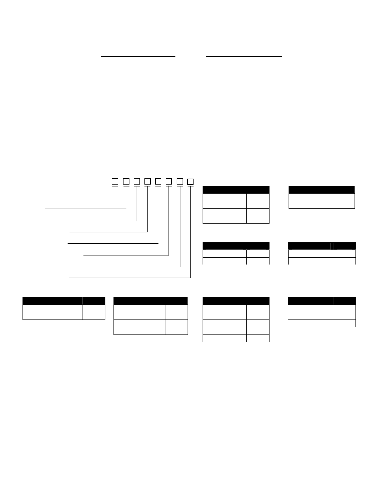
MODEL DESCRIPTION
Input Power
Output
Switch Mounting
Sensor Material
Sensor Length
Process Connection
Flange Size
KUST - - - - - - - -
Flange Material
Description Code Description Code Description Code Description Code
Standard (2.25”) 00 ¾” NPT 1 None None
*Inches (3” – 120”) xxx 150# Flange F 1-1/2” 0 Carbon Steel A
*316SS Sensor Only 300# Flange H 1 1 316SS S
Sanitary Flange S 2 2
3 3
INSTALLATION
Unpack the switch carefully. Inspect all units for damage. Report any damage to carrier immediately. Check the
contents against the packing slip and purchase order.
Kenco’s Ultrasonic Switches are manufactured to the highest quality standards. These switches use electronic
components that can be damaged by static electricity. Make sure that you are properly grounded before starting
installation. Insure that all electrical connections are properly made, and that there are no “floating” connections.
Description Code Description Code
115Vac 1 10A DPDT 1
230Vac 2 Two-wire 2
24Vdc 3
12Vdc 4
Switch Mounting Sensor Material
Description Code Description Code
Integral 1 316SS S
*Remote 2 Tefzel® T
*Remote 10ft. (std.)
100ft. (max)
Page 2
Operational Check
DO NOT
vertical allowing
Vessel Wall
Before installing the switch a simple operational check should be performed, as follows:
1. Fill a container with water
2. Open the electronics housing cover and connect power (see section on “Wiring”).
3. Set the Fail Safe jumper to the LLFS position (lower two pins).
4. Apply power
5. Place the sensor gap into the water.
a. Relay Version -- The relay will energize (the contacts between (NC) and (C) should open).
b. 2-wire Version -- The current in the Positive lead will be 20.0mA.
6. Remove the sensor from the liquid.
a. Relay Version – The relay will de-energize (the contacts between (NC) and (C) should close).
b. 2-wire Version – The current in the Positive lead will be 4.0mA.
7. Disconnect the wiring.
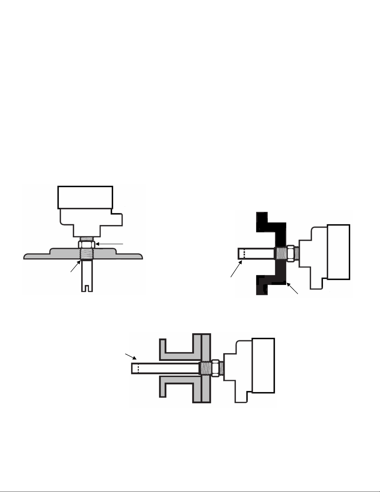
Mounting
For threaded process connections, screw sensor into the opening using a wrench on the sensor mounting nut flats. Use
thread tape or suitable pipe compound on the threads. If flanged, bolt the sensor to the mating flange with the proper
gasket.
The sensor gap must protrude into the vessel / pipe being measured. The sensor will not function properly if the detection
tip is in a nozzle. See the following drawings for mounting guidelines:
housing to
tighten sensor
use
Use wrench here
¾” NPT
Turn slot
media to fall
through
Slot must
extend at least
1” (25mm)
beyond end of
nozzle
Wiring
It is recommended that conduit be installed onto the ¾” NPT connection on the electronics housing. A seal drain fitting
should be used to prevent moisture from entering the switch. All wiring, conduit, and electrical fittings must conform to
local electrical codes for the location selected. If the switch is to be used in a Hazardous Area, the applicable codes of the
National Electrical Code must be followed as well.
Page 3

Relay Version
1. Connect power wiring
a. AC – Hot (L2), Neutral (L2),
and Ground (G)
b. DC – Positive (L1), Negative (G)
2. Connect relay wiring (see diagram)
3. Adjust failsafe jumper
a. HLFS – top (2) pins
b. LLFS – bottom (2) pins
2-Wire Version
1. Connect the power wires as shown in the diagram.
2. Measure the current in the positive lead
a. Dry = 4.0mA
b. Wet = 20.0mA
Specifications
Description Specification
Input Power
Output
Temperature Range
Pressure Range
Sensitivity (Signal-to-noise Ratio) 500:1
Repeatability ±2mm
Response Time (on Alarm) 0.5 sec. non-adjustable
Jumper
High Level Failsafe
(HLFS)
Low Level Failsafe
(LLFS)
Coaxial Cable
To Sensor
Coaxial Cable
To Sensor
{
AC 115Vac or 230Vac; 50/60Hz
DC 12 or 24Vdc
DC (Two-Wire) 9-30Vdc
Relay 10A DPDT
Two-wire (Isolated) 4mA = Dry; 20mA = Wet
Switch -20°F to 170°F
Sensor -40°F to 300°F
316SS Vacuum to 1000psig
Tefzel® Vacuum to 100psig
{
Level
Setpoint
Setpoint
4 or 20mA
- +
GL2L1NCCNONCCNO
+
12 or 24Vdc
}
-
115Vac or 230Vac
}
50/60 Hz
Fail Safe
Setting
HLFS De-Energized Closed Open Above
LLFS Energized Open Closed
HLFS Energized Open Closed Below
LLFS De-Energized Closed Open
Condition
9-30Vdc
}
Relay
Relay Terminals Media
NC to C NO to C
Page 4

TROUBLESHOOTING
Entity Parameters:
NOTES:
Problem Solution
No output change with level change
The output is “chattering”
INTRINSICALLY SAFE CONTROL DRAWING
Check wiring; verify that the correct input
voltage is applied
Verify that liquid is filling the sensor gap
Check for dense foam or dried product in
the gap. Switch may not function properly
if either condition exists.
Check sensor phono plugs for a good
connection. Unplug and Re-plug each
connection.
Check for excessive aeration in process
fluid. This is particularly important in
viscous fluids.
Check wiring; verify that the correct input
voltage is applied
Check for turbulence. Relocate switch or
isolate from turbulence
Check for excessive aeration in process
fluid. This is particularly important in
viscous fluids.
Vmax = 36Vdc
Imax = 150mA
Ci = 0µF
Li = 54µH
1) Vmax > Voc; Imax > Isc; Ci + Ccable < Ca; Li + Lcable < La
2) Dust-tight conduit seal must be used when installed in Class II and Class III environments.
3) Control equipment connected to barrier must not use or generate more than 250V.
4) Installation should be in accordance with the CEC, Part 1.
5) No revision to drawing without prior CSA approval.
6) Associated equipment must be CSA Certified.
7) Associated equipment manufacturer’s installation drawing must be followed when installing this equipment.
8) For wiring refer to installation / operation manual.
 Loading...