

Page 1
KENCO ENGINEERING COMPANY
P.O. BOX 470426 TULSA, OK 74147-0426 ● PHONE: (918) 663-4406 FAX: (918) 663-4406
www.kenco-eng.com e-mail: info@kenco-eng.com
MODEL KUSO ULTRASONIC SWITCH
INSTALLATION / OPERATION INSTRUCTIONS
GENERAL DESCRIPTION
The KUSO Series Ultrasonic Level Switches are ideal, low cost solutions for many liquid level control applications. They
operate in a wide variety of services.
PRINCIPLE OF OPERATION
Ultrasonic switches use piezoelectric crystals to transform electrical energy into mechanical motion (sound). The
Transmit Crystal sends a pulse of sound through the space between the crystals, to the Receive Crystal. If the space is
filled with air, gas, or vacuum, the Receive Crystal does not detect the sound pulse. However, if the space is filled with
liquid, any liquid, the pulse is detected by the Receive Crystal, and the switch output changes.
MODEL DESCRIPTION
KUSO - -
Style
Cable Length
*(In Feet)
*Standard is 1FT.
INSTALLATION
Unpack the switch carefully. Inspect all units for damage. Report any damage to carrier immediately. Check the
contents against the packing slip and purchase order.
Kenco’s Ultrasonic Switches are manufactured to the highest quality standards. These switches use electronic
components that can be damaged by static electricity. Make sure that you are properly grounded before starting
installation. Insure that all electrical connections are properly made, and that there are no “floating” connections.
Operational Check
Before installing the switch a simple operational check should be performed, as follows:
1. Fill a container with water
2. Connect the wiring (see the section on “Wiring”)
3. Apply power
4. Place the sensor gap into the water.
a. Relay Version -- The relay will energize (the contacts between (NC) and (C) should open).
b. 2-wire Version -- The current in the Red wire will be 16.0mA ±1.0mA.
5. Remove the sensor from the liquid.
a. Relay Version – The relay will de-energize (the contacts between (NC) and (C) should close)
b. 2-wire Version – The current in the Red wire will be 4.0mA ± 1.0mA.
6. Disconnect the wiring
Mounting
For threaded process connections, screw sensor into the opening using a wrench on the sensor mounting nut flats. Use
thread tape or suitable pipe compound on the threads. If flanged, bolt the sensor to the mating flange with the proper
gasket.
The sensor gap must protrude into the vessel / pipe being measured. The sensor will not function properly if the detection
tip is in a nozzle.
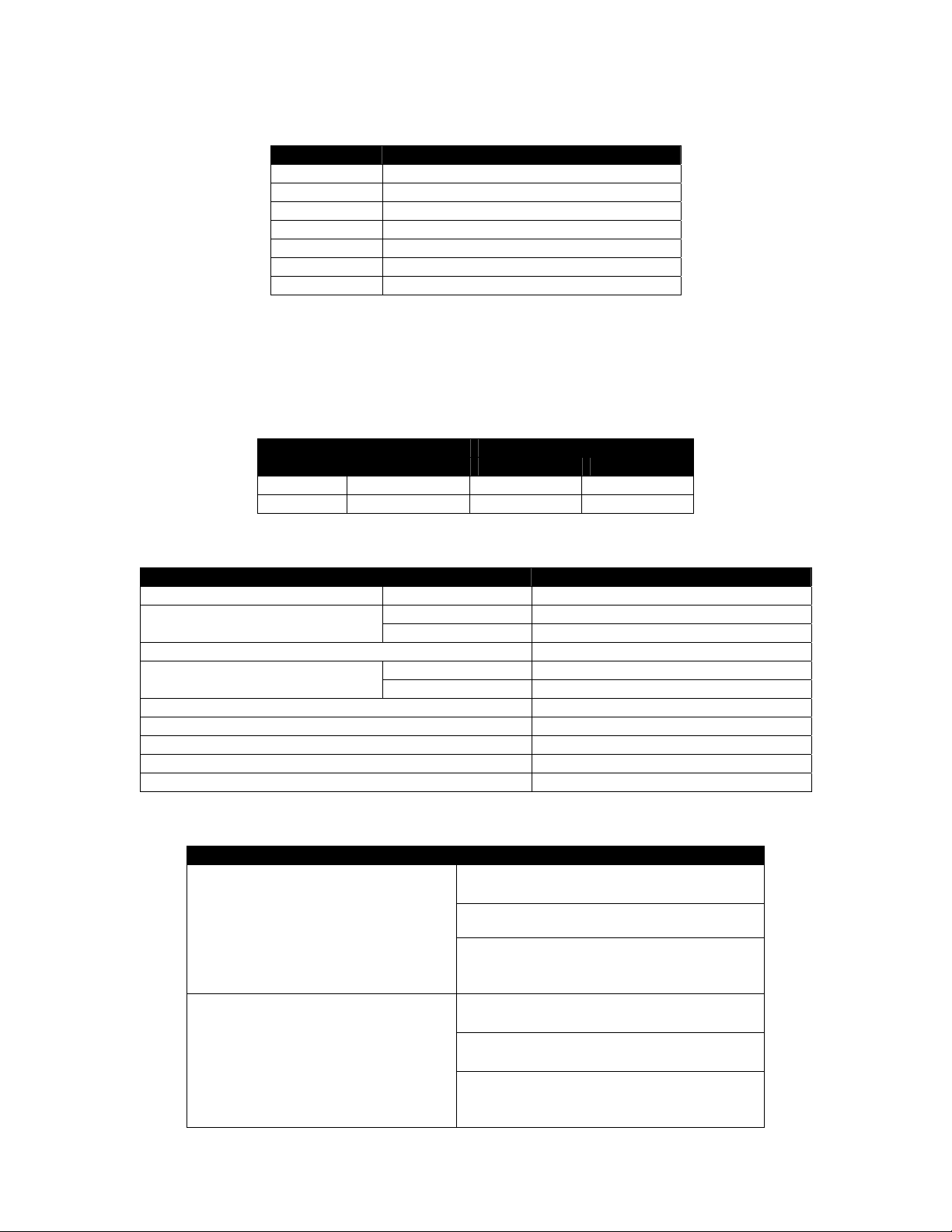
Style
Description Code
1A SPDT 316LSS 0
Page 2
Wiring
It is recommended that conduit be installed onto the ¾” NPT connection on the back of the sensor. A seal drain fitting
should be used to prevent moisture from entering the switch. All wiring, conduit, and electrical fittings must conform to
local electrical codes for the location selected. The wiring color code is shown in the following table:
Color Function
Blue Normally Open Contact (Relay version)
White Common Contact (Relay version)
Brown Normally Closed Contact (Relay version)
Black Power (-)
Red Power (+)
Green Ground
Silver (Bare) Shield
Connect the Black and Red wires to the power source (6 – 24Vdc). If this is the 2-wire loop version, measure the current
in the red wire to determine the output condition (4.0mA ± 1.0mA = Dry; 16.0mA ± 1.0mA = Wet). For the Relay version,
you must also connect the Blue (NO), White (C), and Brown (NC) wires. The Green and Silver (Bare) wires are chassis
ground, and should be connected to earth ground.
The following table shows the relay condition for each switch state:
Relay Terminals Switch
NC to C NO to C
State
Relay
Condition
Dry De-energized Closed Open
Wet Energized Open Closed
Specifications
Description Specification
Input Power DC 6 – 24Vdc, 5Vdc (Optional)
Output
Relay 1A SPDT
Two-wire (Isolated) 4mA = Dry; 16mA = Wet
Temperature Range -20°F to 160°F; up to 212°F (Special)
Pressure Range
316SS Vacuum to 1000psig
®
Tefzel
Vacuum to 100psig
Cable Length 12”; For longer lengths consult factory
Mounting ¾” NPT; For flanges consult factory
Sensitivity (Signal-to-noise Ratio) 500:1
Repeatability ±2mm
Response Time 0.5 sec. non-adjustable
TROUBLESHOOTING
Problem Solution
Check wiring; verify that the correct input
voltage is applied
No output change with level change
Verify that liquid is filling the sensor gap
Check for dense foam or dried product in
the gap. Switch may not function properly
if either condition exists.
Check wiring; verify that the correct input
voltage is applied
Check for turbulence. Relocate switch or
The output is “chattering”
isolate from turbulence
Check for excessive aeration in process
fluid. This is particularly important in
viscous fluids.
 Loading...