

Page 1

KENCO ENGINEERING COMPANY
P.O. BOX 470426, TULSA, OK 74147-0426
PHONE: (918) 663-4406 FAX: (918) 663-4480
http://www.kenco-eng.com e-mail: info@kenco-eng.com
KENCO Loop Powered Magnetostrictive Transmitter
KMD SERIES – Operation and Installation Manual
Table of Contents
__________________________________________________________________________________________
Section Page
1. INTRODUCTION 2
2. PRODUCT DESCRIPTION 2
Mounting Instructions / Transmitter Dimensions 3
3. TRANSMITTER FEATURES 4
4. PRINCIPLE OF MAGNETOSTRICTION 4
5. TRANSMITTER SPECIFICATIONS 5
6A. ELECTRICAL CONNECTIONS AND WIRING PROCEDURES 6
6B. NOTES FOR ELECTRICAL CONNECTIONS 7
6C. LOOP RESISTANCE VS. POWER SUPPLY 8
6D. RECOMMENDED SAFETY BARRIERS FOR INTRINSICALLY 8
SAFE INSTALLATIONS
7. SYSTEM CHECK 9
8. MAINTENANCE 9
9. UNITS OF MEASURE FOR KMD TRANSMITTER 9
10. CALIBRATION PROCEDURES USING FRONT PANEL DISPLAY 10
11. OTHER SETTINGS AVAILABLE ON LCD PANEL DISPLAY 11
12. ADJUSTMENTS FOR TRANSMITTER VIA 11-13
HART‚ COMMUNICATIONS
Page 2

1. INTRODUCTION
____________________________________________________________
KENCO is pleased to update its loop powered magnetostrictive
transmitter with the latest innovations in magnetostrictive
technology, as well as adding new features to the product offering.
The KENCO KMD Series magnetostrictive transmitter is designed
solely for use with the KENCO magnetic liquid level indicator, the
Magna-Site. The transmitter electronically monitors the location of
the magnetic float within the Magna-Site gauge housing, providing
an output in a unit of measure as a % of span or a 4-20 mA output.
The KMD series also incorporates HART® communications and a
visual display as part of the standard offering.
2. PRODUCT DESCRIPTION
_____________________________________________________________
KENCO transmitters electronically monitor the location of the
magnetic float within the Magna-Site gauge housing, providing an
output in a unit of measure as a % of span or a 4-20 mA output. The
transmitter is available up to a length of 300 inches. Zero and span
may be adjusted by using the HART® communications protocol or it
may be manually calibrated using the keypad display inside of the
explosion proof housing. These transmitters operate within a process
temperature range of – 40°F to 300°F. Field replaceable electronics
are potted and encapsulated. KENCO transmitters are available as
standard with NEMA 4X/7 explosion-proof housings. These housings
feature an industrial epoxy coating for corrosion resistance. All
KENCO level transmitters use non-contacting, magnetostrictive
technology. This simple design ensures no scheduled maintenance or
re-calibration – ever. Accurate, non-contact float location sensing is
achieved with absolutely no wear to any of the sensing elements.
Page 3
Mounting Instructions / Transmitter Dimensions
________________________________________________________________________________________________
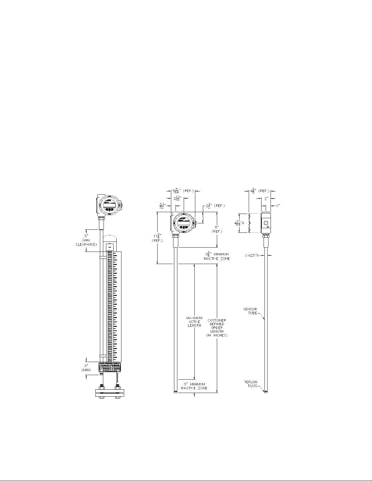
The KMD Transmitter is mounted directly to the housing of the MagnaSite. In a typical application, the magnetic flag assembly is attached to
the gauge housing chamber with hose clamps which have been welded to
the back of the flag assembly, typically 180° from the flanged or threaded
connections to the tank. Install the transmitter at least 90° to the right or
the left of the flag assembly (your choice) by placing the outer pipe of the
transmitter body adjacent to the gauge housing. Tighten the hose clamp of
the flag assembly around the outer pipe of the transmitter. Allow for the
inactive zone of 3 inches at the bottom of the transmitter by placing
transmitter bottom 3 inches below the zero setting. Your application will
allow for 5 inches of clearance at the top of the outer pipe. See dimensional
information below.
Note: In a typical application, KENCO adds 2 inches to the order length so
that the customer has additional mounting flexibility. Units are factory
calibrated with the additional 2 inches at the top of the gauge, bringing the
total inactive zone at the top to 7”.
9999 999999 9999
9999 999999 9999
Page 4
3. TRANSMITTER FEATURES
____________________________________________________________________________________________________________________
• CSA approved explosion-proof enclosure
• Digital Display for zero and span settings and readout
• Readout is updated every 3 seconds
• Readout available as a % of span, a 4-20 mA output or any unit of
measure
• Adjustments may be made using a HART ® hand held communicator
• Repeatability is .005% full span or .005 inches
• Temperature range: - 40°F to 300°F (call KENCO for higher temperature
requirements)
• No maintenance required
• Immune from electrical and mechanical noise
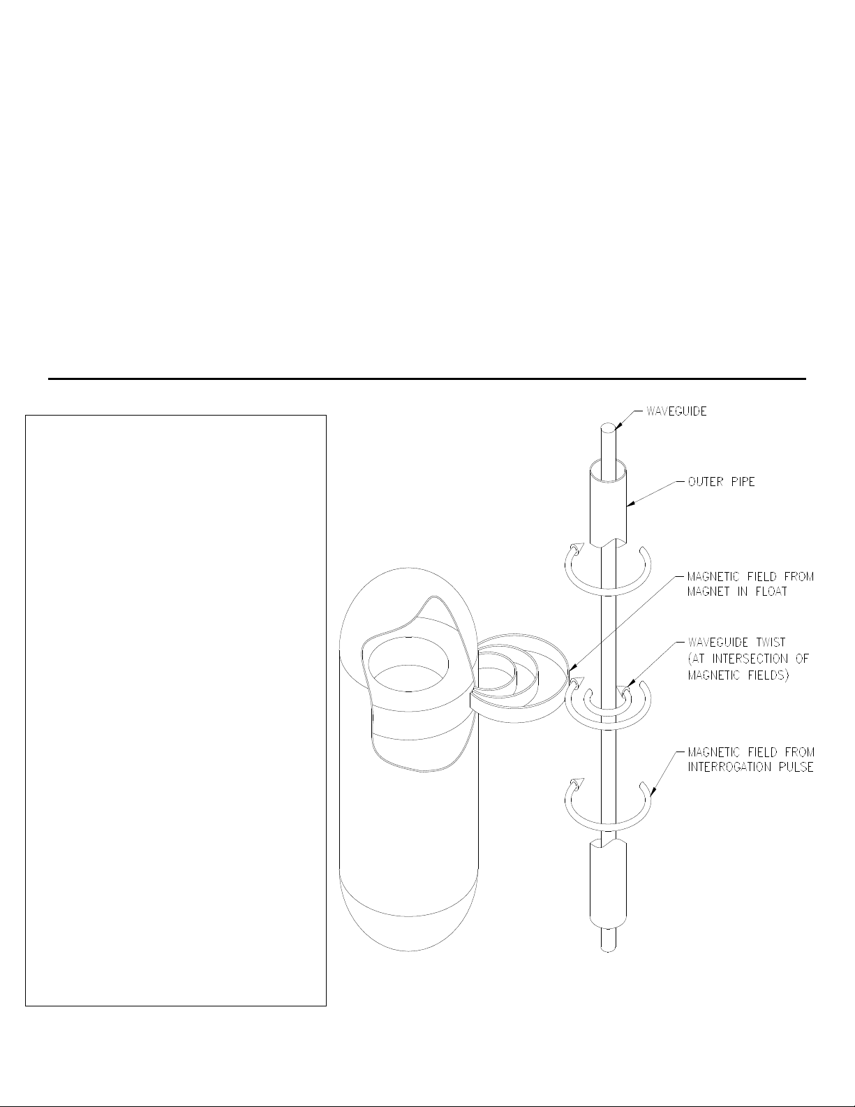
4. PRINCIPLE OF MAGNETOSTRICTION
The level transmitter is composed of 2
concentric members. The outermost
member is a protective 316 stainless
chamber that withstands aggressive
environments. Inside of the chamber
is the waveguide, a formed element
constructed of a proprietary
magnetostrictive material.
A pulse is induced in the waveguide by
the momentary interaction of 2
magnetic fields, one from an electric
current pulse launched along the
waveguide and the other from the
magnets inside the float. This
interaction produces a strain pulse
that travels along the waveguide. The
location of the magnet inside the float
is determined by measuring the
elapsed time between the launching of
the electronic pulse and the detection
of the strain pulse that travels along
the waveguide. The location of the
magnet inside the float is determined
by measuring the elapsed time between
the launching of the electronic pulse
and the detection of the strain pulse by
the sensor head. The time period
measurement is used to produce an
output reading of the float location.
Page 5

5. TRANSMITTER SPECIFICATIONS
________________________________________________________________________________________________________________________
Parameter Specifications
Level Output
Measured Variable Liquid Level (as determined by location of magnetic float)
Full Range 18” to 300”
Non-Linearity Full Span 0.020 F.S. or 1/32”, whichever is greater
Repeatability 0.01% F.S. or 1/32”, whichever is greater
Sensor Operating Temp. - 40°F to 300°F
Transmitter Loop
Input Voltage Range 10.5 to 36.1 VDC
Reverse Polarity Protection Series Diodes
Safety Approval CSA Certified Explosion Proof C1.I, Grps. B, C, D C1.II Grps E, F, G
Division 1, NEMA 4X
CSA Certified Intrinsically Safe (when installed with I.S. Barriers)
C1. I, Grps A, B, C, D; C1. II, Grps, E, F, G. Division 1, NEMA 4X
Calibration
Zero Adjust Range Anywhere within the active length
Span Adjust Range Full scale more than or equal to 0.5” from zero
Environmental
Electronics Operating Temp. - 30°F to 160°F
Humidity 0 to 100% Relative Humidity
Materials/Outer Pipe 316 Stainless Steel
Field Installation
Mounting 3/4” NPT fitting or flange mounting
Wiring 2 wire connection, shielded cable or twisted pair to screw terminals
through a 3/4” NPT conduit opening
Display
Measured Variables Liquid Level
Update Rate: 3 seconds
Size: 0.5”
Number of digits: 16
Measurement: % of span, a 4-20 mA output or any unit of measure
HART® Communications
Method of Communication Frequency Shift Keying (FSK) conforms with Bell 202 Modem
Standards with respect to baud rate and digital “1” and “0” frequencies
Baud Rate 1200 bps
Digital “0” Frequency 2200 Hz.
Digital “1” Frequency 1200 Hz.
Data Byte Structure 1 Start Bit, 8 Data Bits, 1 Odd Parity Bit, 1 Stop Bit
Digital Process Structure Rate Poll//Response Model 2.0 per second
Page 6

6A. ELECTRICAL CONNECTIONS AND WIRING PROCEDURES
___________________________________________________________________________________________________________________
A typical intrinsically safe connection for the KMD Transmitter includes protective safety
barriers, a power supply, and a reading or monitoring device.
Non-Hazardous Locations (Intrinsically Safe):
Hazardous Location:
A typical explosion-proof connection for the KMD Transmitter includes a power supply
and a reading or monitoring device connected via an explosion-proof conduit.
HART® Communications Inside Display Module:
9999 999999 9999
Page 7

6B. NOTES FOR ELECTRICAL CONNECTIONS
_____________________________________________________________________________________________________________
1. For intrinsically safe installations, wiring shall be installed in accordance with the
country in use. Example given: Canadian Electrical Code, Part 1, National Electric
Code ANSI/NFPA 70 Article 504-30.
2. Shielded twisted cable of 24 AWG or heavier should be used. Cable capacitance
shall be less than 30 PF per foot.
3. Control room equipment should not use or generate more than 250 V RMS.
4. For FMRC and CSA approved transmitters barriers must be FMRC and CSA
approved.
5. The connection between the earth ground terminal of FMRC or CSA entity approved
safety barriers and system earth ground must be less than 1 ohm.
6. Safety barriers are FMRC and CSA entity approved safety barriers used in an
approved configuration where transmitter Vmax is greater than barrier Voc and
transmitter Imax is greater than barrier Isc.
7. Transmitter Ci plus total cable capacitance for each loop must not exceed barrier Ca.
transmitter Li plus total cable inductance for each loop must not exceed barrier La
(see note 10).
8. Transmitter enclosure shall be grounded to earth ground through the provided
ground lug in the enclosure.
9. Parameters for each loop entity:
• Vmax = 36v
• Imax = 118 mA
• Ci = 0
• Li = 200 µH
10. HART® communicator must be connected in accordance with manufacturers’ I.S.
installation instructions (FM and CSA approved procedures must be followed).
11. Use only NRTL listed and CSA certified dust-tight seal for Class II and Class III
hazardous locations.
12. CSA file number is LR 81728.
13. Do not use plugged housing entry (at top of enclosure) for termination of conduit.
14. In high humidity areas, use a breather type conduit sealing fitting to minimize
moisture intrusion.
15. Safety recommendations: Always follow applicable local and national electrical
codes and observe polarity when making electrical connections. Never make
electrical connections to the transmitter with power turned on. Make sure that no
wire strands are loose or sticking out of the terminal block connections, which could
short and cause a problem. Make sure that no wire strands, including shield, are in
contact with the electronic module enclosure. The electronics module enclosure is
grounded through internal circuitry and electrically isolated from the explosion proof
enclosure.
Page 8

6C. LOOP RESISTANCE VS. POWER SUPPLY
______________________________________________________________________________________________________________
6D. RECOMMENDED SAFETY BARRIERS FOR INTRINSICALLY
SAFE INSTALLATIONS
____________________________________________________________________________________________________________
NOTES:
1. When selecting barrier types, the electrical specifications for the transmitter are:
• Vmax = 36.1 Vdc
• Imax = 118 mA
• Ci = 0.0 µF
• Li = 0.0 µHy
2. KENCO recommends the following safety barrier:
• Stahl Model Number 9001/01-280-100-10
SAFE OPERATING
POWER
INSUFFICIENT OPERATING POWER
EXCESS OPERATING POWER
Page 9

7. SYSTEM CHECK AND ALARM SETTINGS
______________________________________________________________________________________________________________
System Check
After completing the wiring, the system is ready to be checked out. Apply power to the unit.
Using a DC voltmeter, measure the voltage at Loop 1 connection. The voltage must be
> 10.5 v. If the voltage level is too low, shut down the system. Check for shorts, power supply
voltage, and excessive loop resistance. Refer to the safe operating chart on the previous page,
which shows the relationship between loop resistance and operating voltage.
To test Loop 1 on a bench, move the magnetic float (or a magnet) along the operational range of
the transmitter body. If functioning properly, the output current will change as the float moves.
An output range of less than 4 mA or greater than 20 mA could indicate a problem.
Alarm Settings
When a fault condition is detected by the internal microprocessor, the 4 to 20 mA current will
go to the current selected. If in the 4 mA alarm mode when a fault is detected, the output will
be continuous at 3.8 + 0.1 mA. If in the 20 mA alarm mode when a fault is detected, the
output will be continuous at 21.5 + 0.2 mA.
8. MAINTENANCE
_____________________________________________________________________________________________________________
Removal of Electronic Puck
The transmitter is designed so that the user may remove the electronics module for any reason,
including repair or replacement. Use the instructions below to remove the electronics module:
1. Remove power from transmitter.
2. Remove cover from explosion-proof housing.
3. Gently pull out the electronic puck by raising equally on all sides of the round
puck.
4. Pull electronic puck completely free of connector pins on block cover.
Installation of Electronic Puck
1. Remove power from transmitter.
2. Remove cover from explosion-proof housing.
3. Place electronics puck on top of mating connector pins (2 places) and gently
press down on puck.
4. Press down on puck until connection is made completely.
9. UNITS OF MEASURE FOR KMD TRANSMITTER
_____________________________________________________________________________________________________________
The KMD transmitter can be calibrated to read the following units of measure:
1. mA 4. Feet
2. % of Total Span 5. Centimeters
3. Inches 6. Meters
The unit of measurement must be decided at the time of order placement. Otherwise all
units will be factory set so that the LCD display will readout in 4-20 mA.
Page 10

10. CALIBRATION PROCEDURES USING FRONT PANEL DISPLAY
____________________________________________________________________________________________________________________
The KENCO level transmitter can be bench-calibrated with the display and the three push
buttons. Please follow these procedures:
1. Change the mode of operation from the Run Mode to the Program Mode. To enter the
Program Mode, press any of the following keys: Up, Down or Enter (see diagram
below). Important Note: Upon entering the Program Mode, a one-minute timer is
started. Each time a button is pressed, the timer will be reset. If the operator fails to
press a menu button within one minute, the timer will expire and the display will return to
Run Mode. This automatic timeout feature is incorporated so that the transmitter will
not be inadvertently stuck in Program Mode.
2. Calibrate Level 1? appears on screen. Press Enter.
3. Set Zero? appears on screen. Place magnetic float (or a simple magnet) on outer pipe at
desired zero position. Press Enter key and hold for a one second count. (Unit is
factory set at 3” from end of pipe at the beginning of visual for the flag assembly).
4. Press Enter again.
5. Accept New Value? appears on screen. Press Enter if zero location is acceptable. If
there is a need to reset this zero position, press up or down keys simultaneously to begin
process again from step 2.
6. Calibrate Level 1? reappears on screen. Press Enter.
7. Set Zero? appears on screen. Press down key one time.
8. Set Span? appears on screen. Place magnetic float (or a simple magnet) on outer pipe at
desired span location. Press Enter key and hold for a one second count. (Unit is factory
set at the end of the visual for the flag assembly at the upper end of the gauge.
9. Press Enter again.
10. Accept New Value? appears on screen. Press Enter if span location is acceptable. If
there is a need to reset this zero position, press up or down keys simultaneously to begin
process again from step 7. Calibration is now complete.
11. Once all steps are complete, press all 3 buttons to get out of Program Mode and return to
Run Mode, or allow the Program Mode timer to expire after one minute.
9999 999999 9999
Page 11

11. OTHER SETTINGS AVAILABLE ON LCD PANEL DISPLAY
____________________________________________________________________________________________________________________
Adjust LCD Contrast. This function allows the operator to adjust the brightness of the LCD
readout.
1. Change the mode of operation from the Run Mode to the Program Mode. To enter the
program mode, press any of the following keys: Up, Down, or Enter (see diagram on
previous page).
2. Calibrate Level 1? appears on screen. Press Up or Down key until Adjust LCD
Contrast? appears on screen.
3. Press Enter. LCD Cntrst 0 appears on screen.
4. Using Up and Down keys, you can adjust the brightness of the LCD readout. 0 is the
brightest setting, 3 is the faintest. Press Enter when desired brightness is displayed.
5. Accept? appears on screen. Press Enter. Adjust LCD Contrast function is complete.
6. Once all steps are complete, press all 3 buttons to get out of Program Mode and return to
Run Mode or allow the Program Mode timer to expire after one minute.
Perform LCD Test. This function allows the operator to view all LCD digits available.
Note: Only Level 1 is applicable for the KENCO KMD transmitter. Level 2 and temperature
readings are not applicable.
1. Change the mode of operation from the Run Mode to the Program Mode. To enter the
Program Mode, press any of the following keys: Up, Down or Enter (see diagram on
previous page).
2. Calibrate Level 1? appears on screen. Press Up, or Down key until Perform LCD
Test? appears on screen.
3. Press Enter. All LCD digits are displayed for 10 seconds.
4. Once all steps are complete, press all 3 buttons to get out of Program Mode and return to
Run Mode, or allow the Program Mode timer to expire after one minute.
12. ADJUSTMENTS FOR TRANSMITTER VIA HART®COMMUNICATIONS
_____________________________________________________________________________________________________________________
Refer to the documentation supplied with your specific HART® software package or hand held
communicator for details on performing sensor calibration. Using the HART® interface allows
for calibration of the zero and span without having to remove the unit from the process and
position the magnetic float. The HART® commands 35 and 65 are implemented for this
function. Loop 1 (Zero and Span) is the primary variable.
Calibration set points are given as the absolute displacement from the tip of the sensor. For
example, if the desired zero position is 3 inches, the transmitter will produce 4 mA when the
float is 3 inches from the tip of the transmitter. If the desired span position is 30 inches, the
transmitter will produce 20 mA when the float is 33 inches from the tip of the transmitter.
Page 12

12. ADJUSTMENTS FOR TRANSMITTER (cont’d)
HART® Quick Start
The KMD transmitter can be calibrated using a HART® Model 275 hand-held terminal.
1. Be sure you have the transmitter Loop #1 connected to a load of 250 to 500 ohms.
A unit installed in a control loop is a good example of this loop load. You may also
use a load resistor in the range of the above value.
2. Be sure the transmitter is connected to a clean 24 VDC power supply. Use a linear
supply, as switching types do not provide ripple free power. HART® cannot
tolerate more than a 25 mV voltage ripple.
3. If the unit is installed in a live application, place your automatic controllers in
manual mode and be advised that the output current will change during calibration.
4. Follow safe working procedures as applicable for working on live equipment in a
hazardous location. When safety is secured, remove housing cover.
5. Press the black and black “I/O” button on the HART® terminal. The terminal will
go into self test, then into the main screen. If not connected properly, you will get a
“No device found” message.
6. From the main screen, press keypad #1, “Device Setup”.
7. From the “Device Setup” screen, press key #3, “Basic Setup”.
8. Press key #3, you are now in “Range Values” screen.
9. To Set Low Value: To set low value (4 mA), select key #1, PV LRV (Process
Variable, Lower Range Value). You are now in the PV LRV screen. The current
low value is displayed. Below this value is a highlighted value. Key in the desired
low value (example: 3 inches is shown; if 4 inches is desired, key in 4.). When the
new desired low value is keyed in, press “Enter” (F4) button located below the LCD
display, right. To write the changed lower value to memory, press the “SEND” key
now. Next, you will see two “WARNING” screens that ask if you are sure. If your
new low values are correct, press “OK” for both messages. This action resets the
Lower Range Value, or 4 mA position into the transmitter’s memory.
· Go back to the “Range Values” screen to verify that the new parameters have been
accepted into the transmitter memory.
· You may now exit program mode or continue on to reset the upper value. If you
choose to exit the program mode, replace the calibration jumper to the “ON”
position and return your controllers to automatic.
10. To Set High Value: You should now be in the “Range Values” screen. To set the
20 mA (Upper Range), press key #2. You are now in the “PV URV” (Process
Variable, Upper Range Value) screen. As in the lower value screen, the current
value is displayed with a highlighted number below it. To change the upper value,
key in the desired value. You may use whole numbers or whole numbers and
decimal numbers (40 = 40 inches; 40.5 = 40.50 inches). Whole numbers will be
entered as their decimal equivalents by HART® automatically. Key in the desired
upper range value desired. Press the “Enter” (F4) button.
Caution! Do not enter a high value that exceeds the active length of the sensor!
Page 13

12. ADJUSTMENTS FOR TRANSMITTER (cont’d)
11. You are back in the “Range Values” screen. If the numbers for lower and upper are
correct, press the “Send “ key. You will get a “WARNING!” Press the “OK”
button. You will again get “WARNING!” Press “OK” again.
12. Startup is now complete.
 Loading...