

Page 1

KENCO ENGINEERING COMPANY
P.O. BOX 470426 TULSA, OK 74147-0426
PHONE(918) 663-4406 FAX: (918) 663-4480
www.kenco-eng.com e-mail:info@kenco-eng.com
INSTALLATION INSTRUCTIONS FOR MODEL KLCM OIL LEVEL CONTROLLERS WITH ADAPTERS
(INCLUDING HIGH PRESSURE MODELS)
Note: For fire safe oil level controllers (LCM-FS) see additional instructions in this work sheet covering installation of fire safe
valves.
I. SWITCH SPECIFICATIONS:
Figure 1: Model LCM Switch Wire Color Code
Electrical Ratings:
10 AMP, 125/250 VAC
0.5 AMP, 125 VDC
0.25 AMP, 250 VDC
1/8 HP, 125 VDC
¼ HP, 250 VAC
125 VAC “L”Lamp Load
Circuitry: Single Pole Double Throw
Class III,
Type 4
Note: Switch trip point is factory set at a ¾” drop . For adjustment instructions, please consult the factory.
II. INSTALLATION AND MAINTENANCE INSTRUCTIONS FOR OIL INLET VALVE:
• Connect the oil supply line to the oil inlet on the oil level controller. The minimum recommended supply line is ¾” I.D. The
supply line must be clean and it is recommended that it be flushed with solvent before installation.
• Connect the oil supply line to the oil supply tank. If there is no existing valve at the tank or the existing supply outlet, a shut-off
valve should be placed in the line to prevent oil loss when cleaning the inlet screen or filter.
• For high pressure models HP-A, pressure range must be between 5 psi and 34 psi. For high pressure units HPrange must be between 35 psi and 70 psi.
• The oil inlet valve is adjusted to maintain the oil level at the center of the sight glass. Low or high levels are often caused by
two problems:
1. Excessive oil inlet pressure, which will cause the unit to overfill.
2. Improper equalizing lines between the crankcase and the controller will also result in improper levels.
Note: Low pressure models require a minimum of 2’ of head pressure and a maximum of 15’ of oil inlet head pressure.
B , pressure
III. INSTALLATION INSTRUCTIONS FOR UNITS WITH ADAPTERS:
OIL LEVEL CONTROLLERS WITH –1 (Clark MA & CFA) –2 (Clark HMB & TMB), -3 (Clark RA, HRA, HBA, HCA, HLA,
TLA),
Bessemer BMV & 275) AND FS OPTIONS
• Remove the visual oil gauge assembly from the engine and replace it with the oil level controller and adapter assembly supplied
OIL LEVEL CONTROLLERS WITH
(Cooper-Bessemer GMW), -7 (Cooper-Bessemer GMV), -8 (Cooper-Bessemer GMX),
-6
with a gasket and mounting bolts when applicable.
(Ingersoll-Rand SVG & KVS), -5 (Ingersoll-Rand KVG) AND FS OPTIONS
–4
-16, -16-R, -16-6.25
(Cooper-
• Remove the visual oil gauge assembly from the engine and replace it with the oil level controller and adapter assembly supplied
with a gasket and mounting bolts when applicable.
• If an equalizing exists for the engine sight glass and detach the equalizing line from the sight glass while still attached to the
engine.
• Install the oil controller and then reattach the equalizing line to the vent located at the top of the adapter.
Note: It is important to insure that there are no loops in this line for it must be trap free and self draining.
Page 2

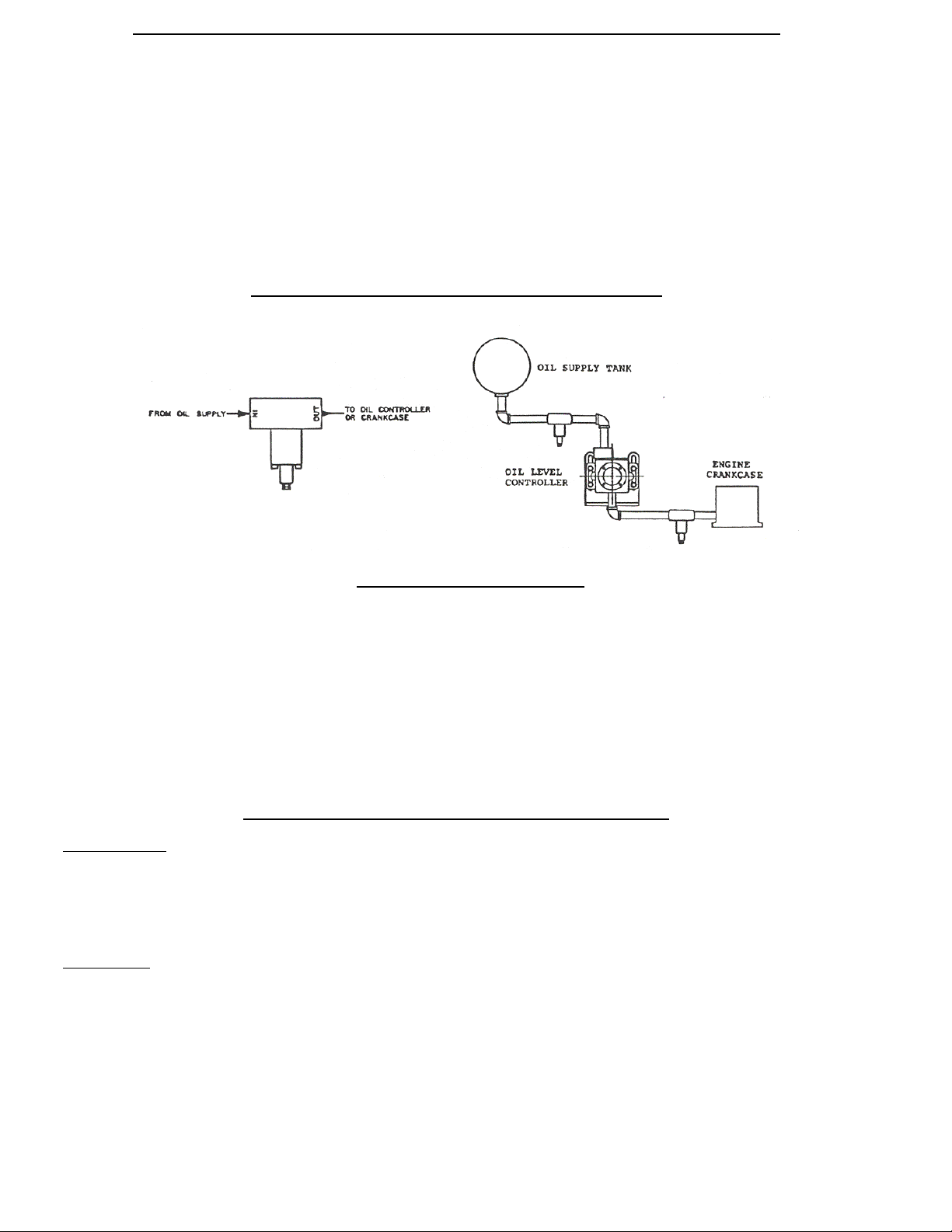
OIL LEVEL CONTROLLERS WITH –9 (Universal adapter),
FS OPTIONS
• Set the controller so that the centerline of the sight window corresponds to the desired oil level in the crankcase.
• Mount the controller close to the crankcase and connect the hose from the ¾” outlet located on the controller to the crankcase.
NOTE: The outlet port on the oil level controller must be located below the oil level in the crankcase.
• An equalizing line must be used between the controller and crankcase in order to equalize the pressure. The tubing must be a
minimum of 1/2” I.D. and must be kept under 2 feet. DO NOT loop this line. It must be trap free and self draining, with a
downward pitch flow by gravity.
(Slotted universal adapter),
-
10
(Pole mounted adapter) AND –
-12
Figure 2: Typical Mount of –9 Adapter
OIL LEVEL CONTROLLER WITH
–11
AND
–11-FS
OPTION (for Mechanical Lubricators): See Figure 3
Figure 3
• Drill holes in the lubricator housing as shown, and mount
the controller with the inlet located on the top side using the
seal washers and mounting bolts provided.
• Place the seal washers between the controller and the
lubricator housing.
OIL LEVEL CONTROLLER WITH
• Remove the triangular blind flange located on the compressor and mount the controller assembly in its place.
–14 AND –14 –FS
OPTION (White Compressor)
Page 3
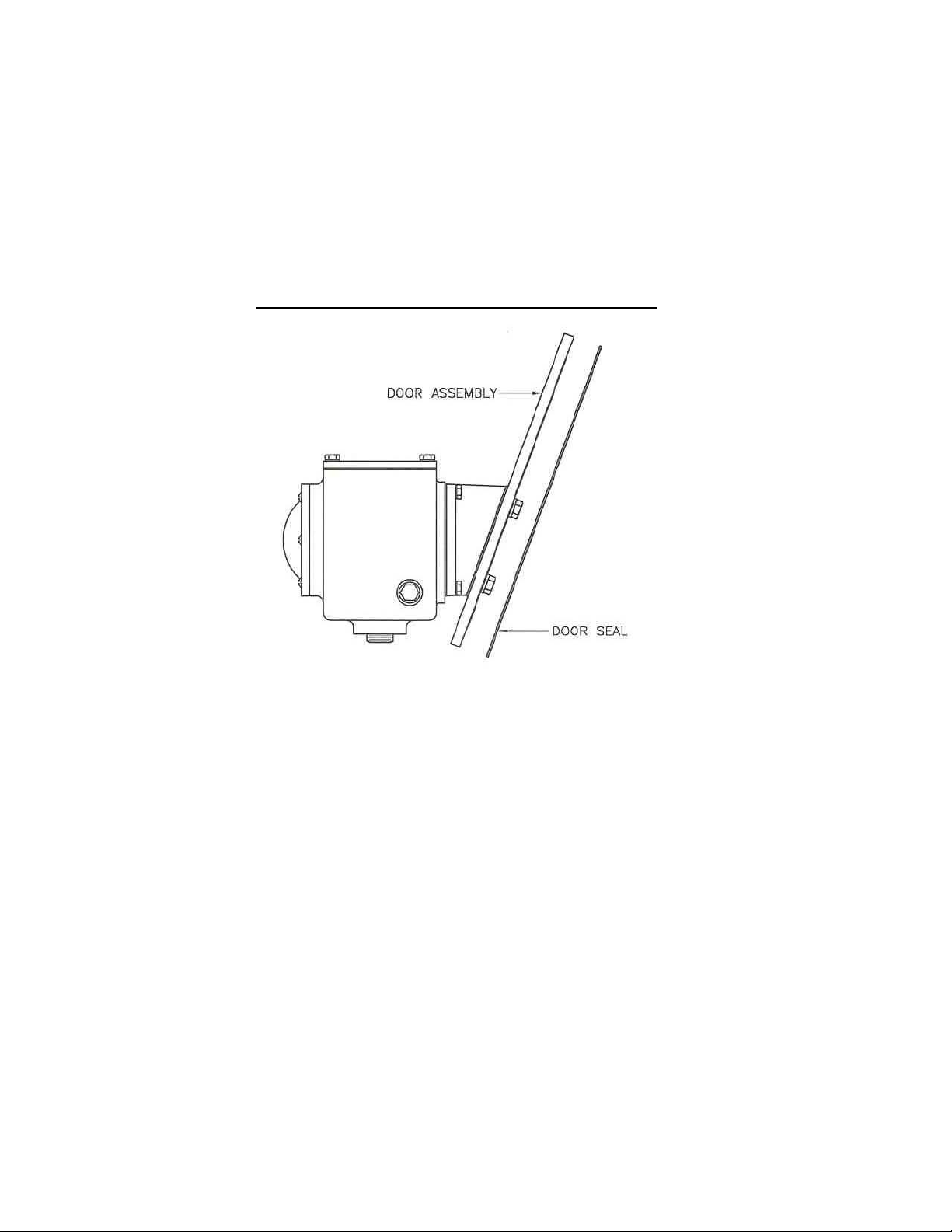
OIL LEVEL CONTROLLER WITH
(for newer Waukesha engines same as –17),
Engines) and –FS OPTIONS
• Remove the cast aluminum inspection door from the engine. Remove the clamp bar from the old door.
• For –17, -18, -37, -38 install the o-ring into the groove of the Kenco door and replace the clamp bar on the back side of the door
using the 5/8” bolts and the stat-o-seals supplied by Kenco.
• For –27, install the o-ring into the groove of the Kenco door and replace the clamp bar on the back side of the door using the
7/16” bolts and the stat-o-seals supplied by Kenco.
• For –47, mount the inspection door with the bolts, seal washers, and gasket provided.
• For –17, -27, -37, -38, place the controller assembly into the inspection port of the engine and tighten the center bolt(s) down.
• Install the equalizing line between the controller cover plate and the door (Tubing and connectors supplied by Kenco).
• Place the controller assembly into the inspection port of the engine and tighten the center bolt(s) down.
• Install oil inlet line into the controller oil valve or the meter inlet port.
• NOTE: For the –18 model, refer to the additional instructions supplied with the 1618 Kenco Low Flow meter.
(Waukesha VHP Engines F2895, F3251, F5108, L5790 & L7042),
–17
(Waukesha P9390),
–37
(same as –37 w/ meter),
-38
-47
(-17 w/ meter),
-18
(Waukesha VGF L36 and P 48
-27
Figure 4: -Door Assembly for –17, -18, -27, -37, -38, -47
OIL LEVEL CONTROLLER WITH
(Ariel compressor JGC & JGD) AND –FS OPTIONS
-48
• Remove the sight glass located on the crankcase and replace it with the oil controller assembly using the mounting bolts and
gasket supplied with the unit.
(Ariel Compressor JGB, JGE, JGH, JGK, JGR, JGT, JGV, & JGW) and
-24
Page 4
IV. INSTALLATION INSTRUCTIONS FOR FIRE SAFE VALVES: See Figure 5 below
MODEL 50-FS AND 75-FS (PATENT NO. 3,877,476)
NOTE: All lines between thermal valves, supply tanks and the controller must be made of steel. DO NOT use rubber hose. The
lines should be 3/4” I.D.
• The eutectic fuse element should always be in a downward position to help the element melt when heat is applied to the valve.
• The 50-FS valve has 1/2” FNPT threads and should be installed in the oil supply line as close to the controller as possible.
Meters, filters and pressure regulators should be installed between the controller and the 50-FS.
• The 75-FS valve has 3/4” FNPT threads and should be located as close to the crankcase as possible and the oil outlet line should
be a minimum ¾” I.D. to insure adequate oil flow to the crankcase.
NOTE: The 75-FS valve is not required when using –FS adapters other than –9 and –12.
FIGURE 5: FIRE SAFE VALVE INSTALLATION
V. START-UP PROCEDURES
• Flush the supply system and supply line with solvent to remove all burrs and construction debris.
• Insure that the oil supply tank is full.
• After the engine has been running for 1 hour, visually check the oil level in the sight glass. The oil level should be in the center
of the sight glass.
• With the engine running, check the crankcase oil level. It should be the same as the oil level in the oil controller. If not, check
the installation of the equalizing line (if applicable) see instruction for the equalizing line at –9.
• Check all piping connections for leaks and repair as needed.
VI .SIX MONTH SUGGESTED MAINTENANCE PLAN
Oil Valve Service
• Close the oil supply valve and discount the oil inlet supply line.
• Place a pan under the controller to catch the oil from the oil supply line.
• Remove the inlet oil housing and clean the screen.
• Once the screen is clean, reassemble and open the oil supply valve.
Note: Dispose of oil in a proper container.
Switch Service
• Test switches to insure that the switches are operating correctly.
• Shut the engine off.
• Disconnect the equalizing line (if applicable).
• Place a blunt rod through the vent hole on the cover plate and depress the oil float.
• Observe the engine panel to determine if the switches make and break contact.
• If the switch is functioning properly, replace the equalizing line or vent plug.
• If the switch does not function, it must be replaced (refer to a replacement parts list).
 Loading...