

Page 1
KENCO ENGINEERING COMPANY
P.O. BOX 470426 TULSA, OK 74147-0426 ● PHONE: (918) 663-4406 FAX: (918) 663-4406
www.kenco-eng.com e-mail: info@kenco-eng.com
MODEL KEFS LIQUID LEVEL FLOAT SWITCH
INSTALLATION / OPERATION INSTRUCTIONS
PRINCIPLE OF OPERATION
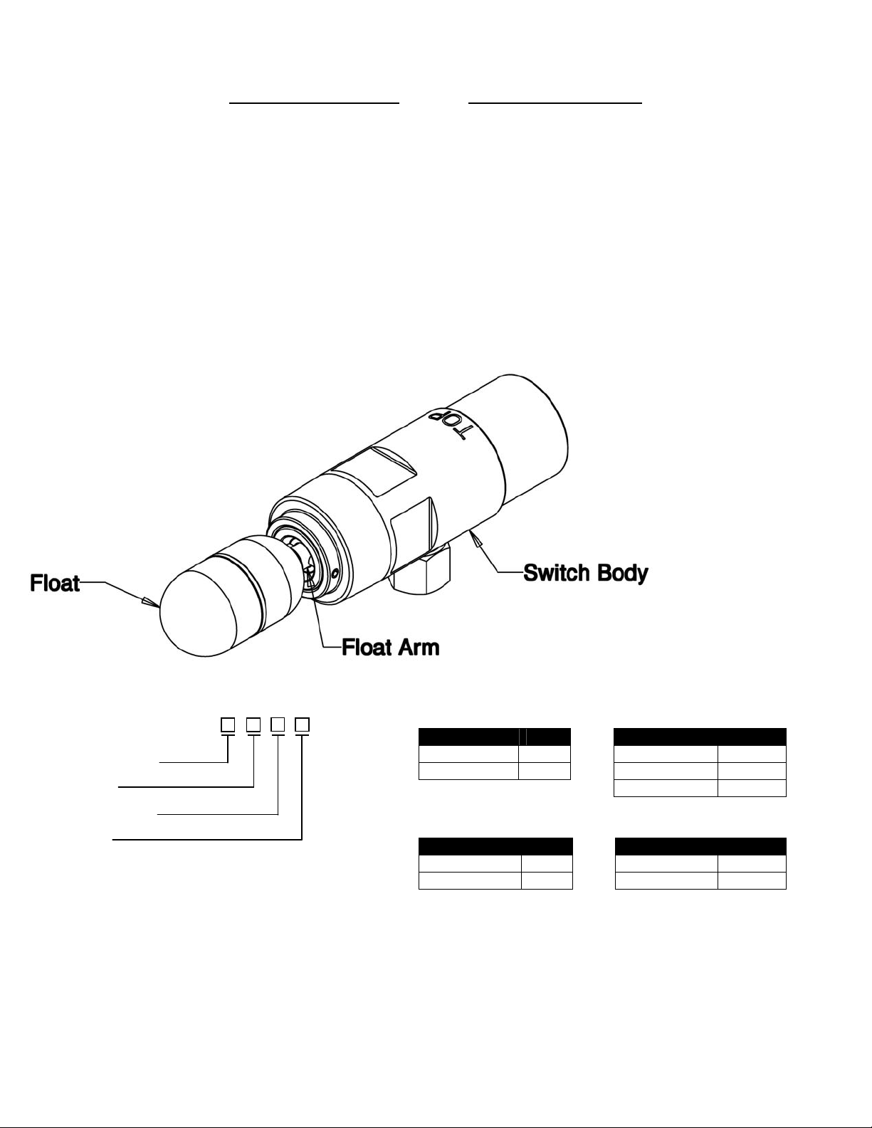
The Model KEFS uses a float to determine the presence or absence of liquid at the process connection. The float arm assembly
consists of a float at one end and a magnet at the other. As the level rises, the float rises, and the magnet falls. The magnet
actuates a second magnet on the other side of the pressure boundary. This second magnet causes the switch to change state.
The pressure boundary contains no seals; it is a solid stainless steel barrier that passes a magnetic field, but no liquids. It is
impossible for the process liquid to enter the switch enclosure through this barrier.
The electrical contacts consist of a microswitch that can be either a Single-pole, Double-throw (SPDT) or Double-pole, Double-throw
(DPDT) Configuration. The SPDT Switch is available with either a 5 Amp or 8 Amp current load. The DPDT is available with a 5
Amp/30Vdc current load (See Switch Types and Ratings in the Product Specifications for more details).
MODEL DESCRIPTION
Process Connection
Switch Rating
Temperature Rating
Wetted Parts
KEFS - - - -
Process Connection Switch Rating
Description Code Description Code
1½” NPT N/A 5A SPDT SPDT5
2” NPT (std.) 2 4A DPDT DPDT4
8A SPDT SPDT8
Temperature Rating Wetted Parts
Description Code Description Code
Standard
blank
303 SS (std.)
blank
High* 400 316 SS S6
temperature option only available with 5A SPDT switch
* High
(58639 Rev B)
Page 2
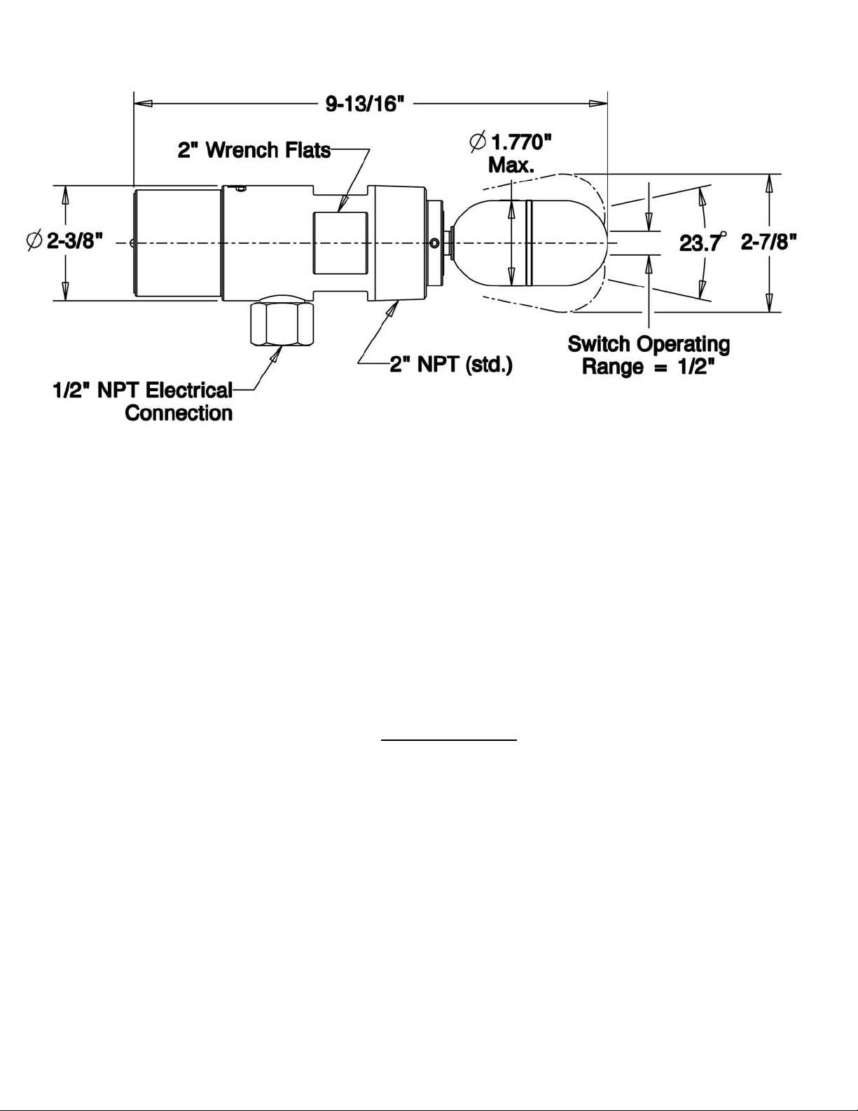
SWITCH DIMENSIONS
INSTALLATION
Unpack the switch carefully. Inspect the unit(s) for damage. Report any damage to carrier immediately. Check the contents against
the packing slip and purchase order.
Operational Check
Before installing the switch a simple operational check should be performed, as follows:
1. Remove the Switch Housing Cover
2. Connect an Ohmmeter to CM1 and NC1 (See Wiring section).
3. With the conduit connection pointing downward, the “TOP” label facing upward, and the float downward (at rest), the
Ohmmeter should be showing approximately 0Ω.
4. Lift the float up. The Ohmmeter should be showing infinite Ω (some digital meters will show OL).
5. Disconnect the Ohmmeter
Mounting
1. Make sure the float will not be obstructed by the coupling, vessel wall or other vessel components.
2. To prevent galling, Kenco recommends the use of RectorSeal Virgin 100
pipe sealer with Teflon or an equivalent Teflon
based pipe sealer. Apply pipe sealer liberally to the threads of the switch.
3. Screw the switch into the process vessel by hand until snug. Tighten at least one full turn until switch is level and the ½-14
NPT conduit connection is on the bottom. To make sure switch is in the proper operating position place a level on the
wrench flats.
Wiring
It is recommended that conduit be installed onto the ½” NPT connection on the switch body. A seal drain fitting should be used to
prevent moisture from entering the switch. All wiring, conduit, and electrical fittings must conform to local electrical codes for the
location selected. If the switch is to be used in a Hazardous Area, the applicable sections of the National Electrical Code must be
followed as well.
(Note: The SPDT5-400 high temperature option is wired differently than the other KEFS models. It does not have a terminal blo ck
and uses four 18 AWG color coded wires instead. It has a separate wiring instruction sheet that is included as an addendum to this
one)
Page 3
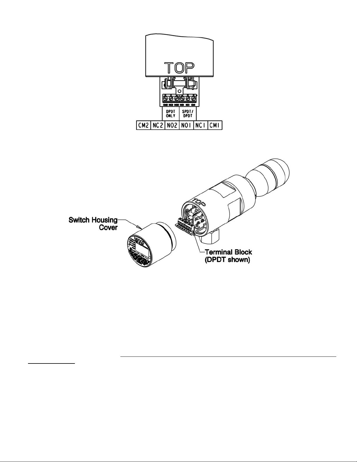
WIRING TERMINALS
CM = Common; NC = Normally Closed; NO=Normally Open
1 = Used in both SPDT and DPDT Switches; 2 = Used in DPDT Switches Only
1. Remove the switch housing cover.
2. Feed wire up through the conduit (user supplied) and conduit opening, and out through the opening below the terminal
blocks, taking care not to damage insulating paper on bottom of circuit board inside unit.
3. Do not use any more wire than is necessary to make the connections. Make sure that any excess wire is stored below the
terminal block / circuit board. Too much wire inside the switch cap could interfere with the operation of the switch
mechanism.
4. The terminal block is designed to handle 16 AWG to 22 AWG stranded, insulated wire. Be sure to size the wire appropriately
for your electrical loads. If in doubt, use 16 AWG. Strip approximately ¼” of insulation off of the wire.
5. See the following table for the switch connections:
6. Insert the wire into the appropriate terminal, and tighten the screw. Make sure that the screw is snug enough, so that the
wire will not fall out of the terminal. Do not over tighten! Damage to the terminal block could occur, which will render the
switch inoperable!
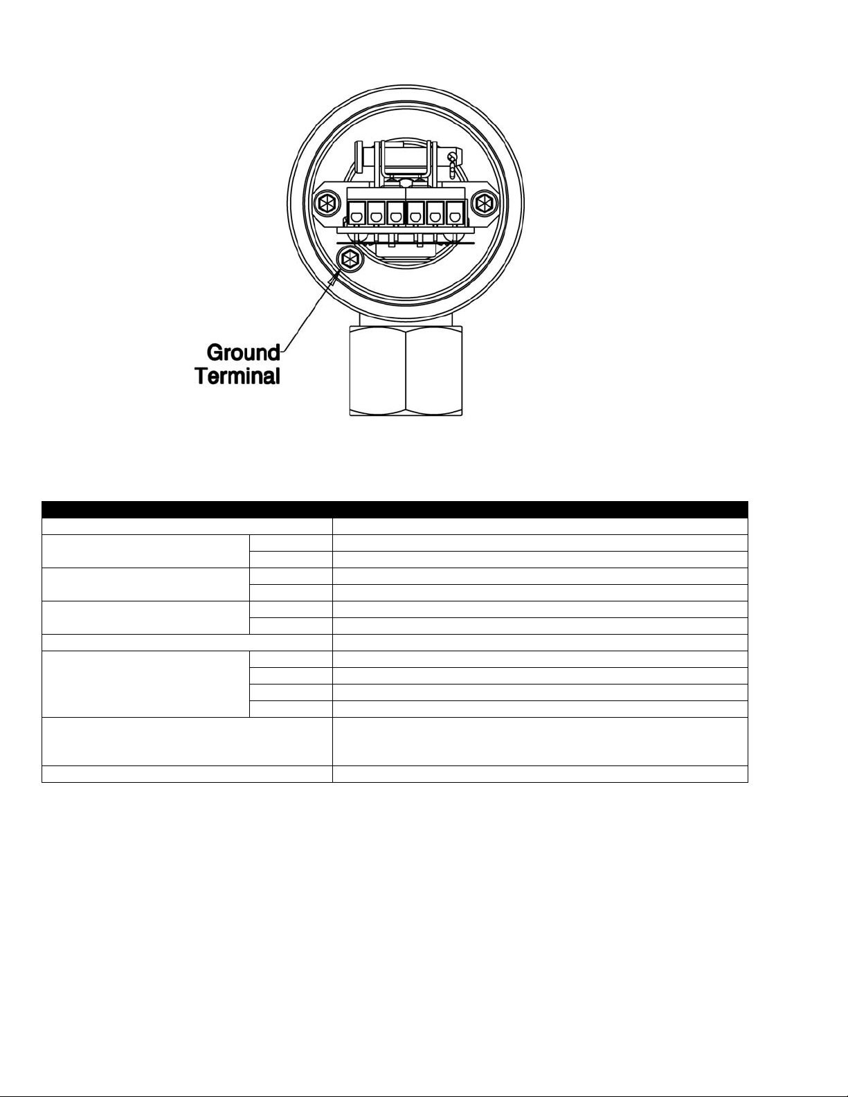
7. Crimp a #8 ring terminal of the appropriate wire gage to the ground wire and attach to the ground terminal shown.
Page 4
8. Carefully reinstall the Switch Housing Cover; BE CAREFUL not to pinch the wires
PRODUCT SPECIFICATIONS
Description Specification
Specific Gravity ≥ 0.53
Wetted Parts Material
Process Connection Size
Temperature Range
Process Pressure Range Vacuum to 2000psig
Switch Types & Ratings
Housing Rating (CSA Certified)*
Conduit Connection ½” – 14 NPT
Standard 303 SS
Optional 316 SS
Standard 2” NPT
Optional 1½” NPT (Not yet available)
Standard -67ºF to 257ºF (-55ºC to 125ºC)
Optional -40ºF to 400ºF (-40ºC to 205ºC)
Standard SPDT; 5A @ 250Vac; 5A @ 30Vdc resistive
Optional SPDT; 8A @ 250Vac; 12A @ 125Vac resistive
Optional DPDT; 4A @ 250Vac; 5A @ 30Vdc resistive
Optional SPDT(-400 high temp. option); 5A @ 250Vac; 0.3A @ 125Vdc
Division 1; Class I; Groups C & D
Class II; Groups E, G
Class III; Type 4X/7/9;
*Excludes high temperature version of the KEFS with the SPDT5-400 Option
 Loading...