

Page 1
X
KENCO ENGINEERING COMPANY
P.O. BOX 470426 TULSA, OK 74147-0426
PHONE: (918) 663-4406 FAX: (918) 663-4480
MODEL KDV SERIES “FREEZELESS” DUMP VALVE
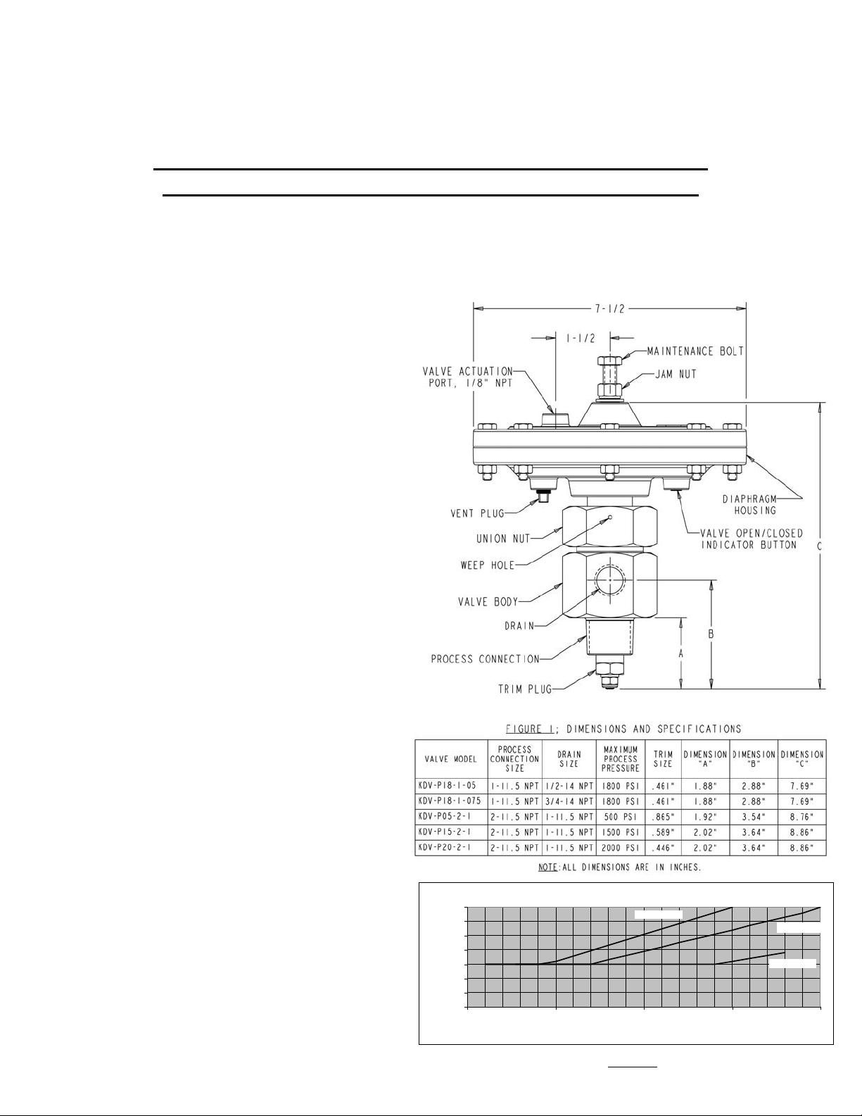
The Kenco KDV series Dump Valve is a pneumatically controlled valve designed for fluid level control
in gas scrubbers, separators and other process pressure vessels. It is available with either 1” or 2”
process connections. The drain sizes available are ½”, ¾” and 1” depending on the model used. The
valve actuation pressure range is 30-70 psi depending on the model and process pressure (see figure 2).
Process pressure ratings of up to 2000 psi are available.
•Features:
•Ease of Maintenance-The union nut allows the
valve to be removed for service without removing
the Valve Body from the pressure vessel.
•Variety of Trim Sizes- Several trim sizes
available to accommodate different flow and
pressure requirements.
•High Performance Polyurethane Trim Seal-The
high performance polyurethane material used on the
Trim Seal is more durable and longer lasting than the
urethane used on competitive valves.
• Pressure Warning Port-If an attempt is made
to remove the valve assembly from the body
while the valve is under pressure, process fluid
and/or gas will leak from the weep hole to provide
a warning.
• “Keyed” Housing to Valve Joint-Valve is
keyed to diaphragm housing to ensure internal
retaining hardware does not twist or vibrate loose.
•Simple Installation-Valve is easily installed
with simple hand tools in a short amount of time.
Specifications:
Operating Temperature: -30 to 250°F
(-34 to 21°C)
Operating Process Pressure: Up to 2000 psi,
depending on model (See figure 1)
Valve Actuation Pressure: 30 to 70 psi
depending on process pressure (see figure 2)
Body Material: Nickel Plated 12L14 Carbon
Steel
Wetted Materials: Nickel Plated 12L14 Carbon
Steel, 303 Stainless Steel, Buna, Polyurethane.
FIGURE 2
56588 (Rev C)
Web: www.kenco-eng.com e-mail: info@kenco-eng.com
INSTALLATION AND OPERATING INSTRUCTIONS
70
60
50
40
30
(PSIG)
20
10
Actuation Pressure
0
0 500 1000 1500 2000
(NOTE: KDV-P05-2-1 HAS A CONSTANT ACTUATION PRESSURE OF 30 PSIG)
Actuation Pressure vs. Vessel Pressure
KD V-P15-2-1
Process Pressure (PSIG)
KD V-P18-1-X
KD V-P20-2-1
Page 2

INSTALLATION OF KDV SERIES DUMP VALVE
1. Prior to valve installation, inspect the unit for damage from shipping. Inspect the inlet (process
connection) and drain to ensure no foreign material or debris is present.
2. Install valve using good piping practice. Use an appropriate pipe sealant on all NPT threads.
3. Make sure drain is facing down. Also make sure the vent plug is positioned at the bottom of the
valve before tightening the union nut. If necessary, the union nut can be loosened to orient the
diaphragm housing in the proper position. Be sure to tighten the union nut up firmly before
putting the valve into service or leaking may result.
4. Connect the 30 to 70 psi pneumatic input signal to the valve actuation port. Always use clean,
dry instrument quality air or gas.
5. To ease assembly and maintenance, plumb a union connection between the valve drain port and
the condensate/drain line of the pressure vessel. Kenco also recommends a manual 2-way shut
off valve installed in the process vessel at a level below the dump valve. The outlet on the
manual valve should be connected to the condensate/drain line.
TROUBLESHOOTING
Problem
Valve leaks when closed. 1. Debris between plug and
4. Crush washer excessively
5. Maintenance bolt is screwed
Valve will not open. Pressure drop across valve too
great.
Air/gas leaking from diaphragm
housing.
1. Diaphragm damaged. 1. Replace diaphragm.
Possible Cause Solution
1. Remove debris.
seat.
2. Plug and/or seat worn
3. Union nut not tight enough.
worn.
in too far, pushing the trim
plug off of the trim seat
2. Replace trim plug and seat.
3. Tighten union nut.
4. Replace crush washer.
5. Unscrew the maintenance
bolt until the trim plug is
fully seated against the trim
seat.
1. Increase pneumatic input
signal to 70 psi.
2. Make sure process pressure is
not higher than KDV-Dump
Valve rating.
WARNING!
Always make sure the process pressure is fully relieved, or zero before doing any
maintenance or assembly/disassembly to the valve!
MAINTENANCE AND REPAIR PROCEDURES
PREVENTATIVE MAINTENANCE
1. Inspect Trim Plug and Trim Seat for wear every 6 months.
2. Inspect Diaphragm, Thrust Plate and Trim Shaft for wear or damage once a year.
Page 3

TRIM SEAL REPAIR PROCEDURE
1. Make sure all the pressure is off of the pressure vessel and the condensate is drained to a level
below the valve inlet. Also ensure the pressure is off the pneumatic input signal.
2. Disconnect the pneumatic input signal.
3. With a wrench on the union nut and a back-up wrench on the valve body, break the union nut
loose.
4. While removing the union nut, make note of the weep hole. If at any time, pressure is escaping
through the weep hole, STOP! Tighten the union nut and check the vessel shut down and
depressurizing procedures to make sure no pressure is on the valve. NEVER remove the valve
while pressure of any kind, no matter how low, is present in the vessel.
5. With the union nut removed, slide the valve assembly out of the valve body.
Figure 2
6. Loosen the jam nut (#11) and spin it all the way to the top of the maintenance bolt (#10). (See
Figure 2)
7. Screw the maintenance bolt (#10) in until it bottoms and lightly snug. DO NOT OVER
TIGHTEN. This will take the spring load off of the trim plug, allowing for its removal.
8. With a wrench backing up the trim plug (#4) break the lock nut (#1) loose. Once the lock nut is
loose, backing up the trim plug is no longer necessary. The maintenance bolt and diaphragm
assembly will provide the resistance needed to remove to locknut.
9. With the locknut removed, remove the washer (#2), o-ring (3), trim plug (#4), crush washer (#5)
and trim seat (#6). Also remove the o-ring (#8) from the spud (#9) under the union nut. (Note: if
fluid was leaking from weep hole, then replace packing (#26)).
10. Replace all of the parts in the reverse order they were removed. Lubricate the O-rings (and the
packing if replaced) with Parker O-ring lubricant or equivalent.
11. When installing the new locknut (#1) on the trim shaft (#7) screw it on until it just contacts the
trim plug (#4). Then, using a wrench to back up the trim plug (#4) tighten up the locknut (#1).
12. Loosen the maintenance bolt (#10) until the trim plug (#4) is firmly in contact with the trim seat
(#6). Back the maintenance bolt up another couple of turns to make sure it does not come in
contact with the trim shaft during normal operation.
13. Spin the jam nut (#11) down against the housing and tighten. The KDV Dump Valve is ready
for operation.
Page 4

DIAPHRAGM AND TRIM SHAFT REPLACEMENT
1. Remove the trim plug and seat following steps 1 through 9 under Trim Seal Repair Procedure.
2. Remove the maintenance bolt (#10), nut (#11), flat washer (#12) and seal washer (#13). This will
take most of the load off of the valve spring, making the next step easier. (See Figure 3)
Figure 3
3. Make an alignment mark on the housing halves (#16, #19) and remove the eight ¼ “ nuts (#15)
and bolts (#14). The valve spring (#18) will probably force the 2 housing halves apart, but if not,
gently pry the halves apart with a flat tip screwdriver. Take care not to gouge the sealing surface
of the housings.
4. With the two halves apart, remove the old diaphragm assembly (#17).
5. If the valve is a 2” model, slide the washer (#26) on the shaft. Make sure the flat side of the
washer sits on the shoulder of the shaft and that the proper end of the shaft is selected.
6. Install the new thrust plate (#23) with the edge of the rolled lip facing the body side of the
housing (#19) Use the old assembly for reference if necessary. Also install the diaphragm (#22),
washer (#21) and nut (#20). If the valve is a 2” model, the washer (#21) will have a counter bore
on one side. This counter bore must
properly will result in leakage and early valve failure. This only applies to the 2” KDV’s.
7. Use a 1-1/8” wrench to back up the hex end of the trim shaft (#24) and tighten the nut (#20) to
220 in lbs (1”KDV) or 180 in lbs (2” KDV) or until it slightly compresses the surface of the
diaphragm (#22).
8. Remove the o-ring (#25) and insert the new o-ring into the groove in the spud (#9 in figure 2).
Use plenty of o-ring lubricant.
9. Smear a thin coat of O-ring lube on the shaft (#24) near the end with the hex. This will help
lubricate the o-ring and packing and will improve the life of these seals.
10. Insert the shaft into the spud on the housing (#19). If the valve is a 2” valve, the shaft will have a
fairly sharp edge on the shoulder the trim plug (#4 figure 3) bolts up against. Use care when
inserting the shaft. The shaft should be gently rotated while applying some pressure to push it
past the O-ring (#25). If caution is not used here, the O-ring (#25) and or packing (#26 figure 2)
could be damaged.
11. It is easiest to install the packing (#26 figure 2) after the diaphragm assembly is completed.
Simply lube the packing thoroughly and work it gently over the trim shaft. Make sure it is
oriented properly. The narrow end will sit in the bottom of the groove and the wide end should
face the trim plug. Warning! If this seal is put in backwards, the valve will leak fluid and/or gas
out of the weep hole. Use the trim seat (#6 Figure 2) to fully seat the packing in the groove.
12. Assemble the rest of the valve following steps 10 through 13 under Trim Seal Repair Procedure.
face the diaphragm (#22). Failure to orient this washer
 Loading...