

Page 1
KENCO ENGINEERING COMPANY
K
- - -
P.O. BOX 470426 TULSA, OK 74147-0426 ● PHONE: (918) 663-4406 FAX: (918) 663-4406
www.kenco-eng.com e-mail: info@kenco-eng.com
MODEL KMR, KMT, KHR, AND KHT FLAT GLASS GAUGES
INSTALLATION / OPERATION INSTRUCTIONS
GENERAL DESCRIPTION
Kenco Flat Glass Gauges are simple, rugged instruments engineered and constructed throughout to give you accurate
liquid level readings for the life of the vessel. We offer a complete range of gauges suitable for most applications. Like
any instrument, Kenco flat glass gauges must be installed, operated, and maintained with reasonable care and due regard
for the application, and the environment, if they are to give accurate readings over a long life.
This instruction sheet covers medium and high pressure gauges, as well as, large chamber gauges. Weld Pad gauges
are covered in a separate instruction sheet. Contact Kenco if you need the Weld Pad sheet.
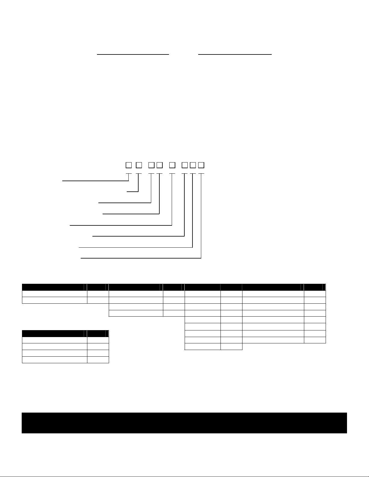
MODEL CONFIGURATOR
Gauge Type
Style (R – Reflex; T- Transparent)
Sections – (1 through 9)
Glass Size – (1 through 9)
Construction
Connection Location
Connection Size
Connection Type
Gauge Type Connection Location Connection Size Connection Type
Material Code Gauge Code Size Code Type Code
Medium Pressure M End E ½” 50 NPTF N
High Pressure H Side (Right) R ¾” 75 Socketweld (Female) S
Side (Left) L 1” 1 150# ANSI Flange A
Back B 1½” 15 300# ANSI Flange B
2” 2 600# ANSI Flange C
Construction
Material Code
Carbon Steel C 6” 6 2500# ANSI Flange F
Stainless Steel Wetted W 8” 8
All Stainless Steel A
Special X
INSPECTION & DELIVERY
Upon receiving the gauge, check all components carefully for damage incurred in shipping. Notify the shipping company
immediately of any such damage, and request a damage inspection. Confirm that the gauge model number and
pressure/temperature ratings (located on the nameplate) match the application conditions. Also, confirm that the gauge
materials are compatible with the process media and the environmental conditions around the gauge.
CAUTION – Kenco Gauge Glasses are not to be used for indicating the level of lethal substances as defined
by ASME Section VIII.
3” 3 900# ANSI Flange
4” 4 1500# ANSI Flange E
D
Page 1
Page 2
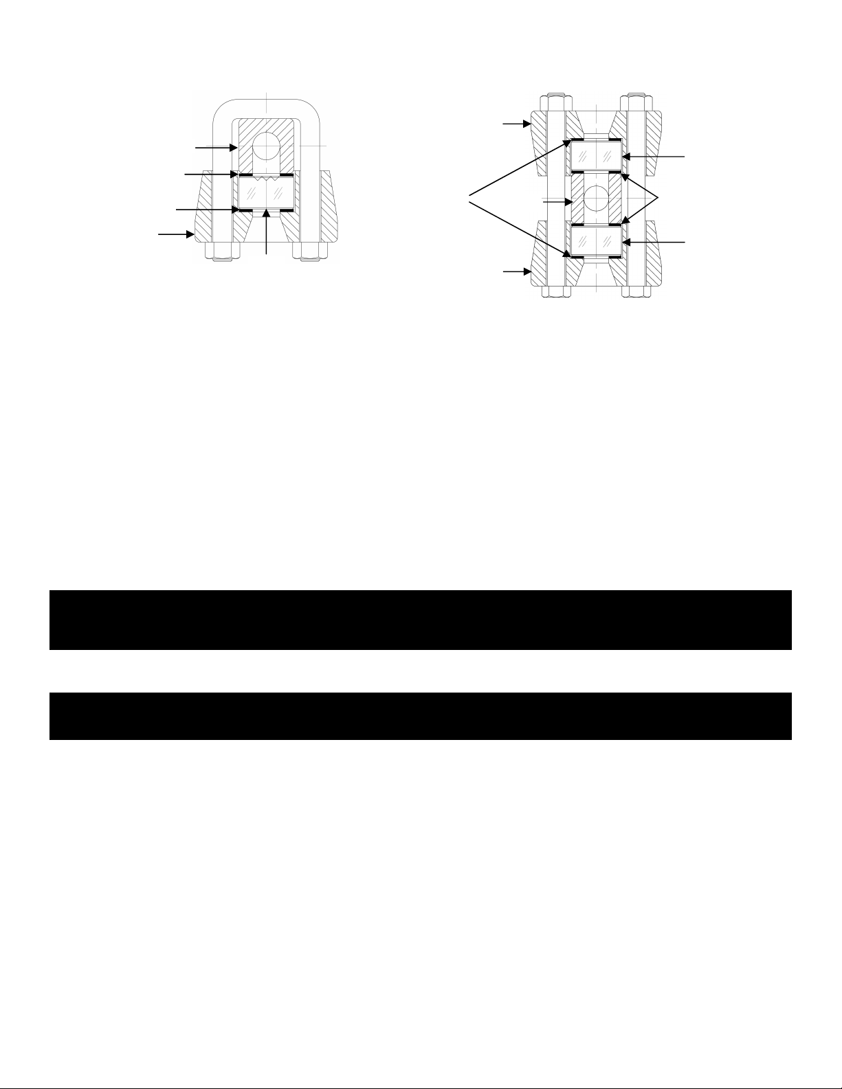
GAUGE CONSTRUCTION
Glass
Chamber
Gasket
Cover
Glass
Cover
Glass
BEFORE YOU INSTALL THE GAUGE
Consider the following:
• To avoid imposing piping strains on the gauge chamber, connect and mount the gauge so that it does not support
• Differential thermal expansions between the vessel and gauge can impose severe mechanical loads on the
• Support brackets should be considered for gauges over four feet in length or over 100 pounds in weight,
• Always provide shutoff valves between the gauge and vessel. Kenco automatic ball check valves are
• Bolt torque is vital to the proper operation of a flat glass gauge. Because gaskets compress over time, bolt torque
CAUTION – Gauges should always be isolated from the process system by closing the upper and lower
OPERATION
CAUTION – Rapid opening of connecting valves can cause glass breakage and / or possible injury to
Always warm up the gauge slowly when it is used with a vessel containing a hot fluid. Slowly open the shutoff valves
carefully, and wait until the gauge is fully warmed up before completely opening the valves. Kenco Gauges use tempered
glass, designed to withstand thermal shock. However, additional loads that you cannot measure are imposed on the
glass during installation. Resistance to thermal shock is reduced accordingly. This procedure also applies to cold fluids.
During system shutdown, it is best to leave the shutoff valves open so that as the gauge cools it depressurizes along with
the rest of the system. Keeping valves closed during shutdown can trap high pressure liquid in the gauge. For high
pressure / temperature applications a viewing system of mirrors should be used to protect personnel from physical injury
in the event of glass breakage.
Gauges should be isolated periodically and bolt torque checked to prevent leaks. This is especially important on gauges
used in intermittent operation, or varying service conditions. When putting a gauge into service always check for leaks
and be certain the shutoff valves are fully open with all vents and drains closed before leaving the site.
Reflex Gauge (Model KMR & KHR)
Cushion
Cover
the piping.
gauge, especially if the vessel contains hot or cryogenic liquids. To prevent these, install an expansion loop
between the gauge and vessel, or use a reasonably long run of piping.
especially when the gauge is exposed to vibration. These support brackets will prevent overloading the
connecting valves and piping and prevent damage to the gauge from excessive vibration.
recommended to provide protection against physical injury and loss of product if glass breakage should occur.
These valves also provide a means to isolate the gauge for maintenance.
should be checked before the gauge is installed (see MAINTENANCE). Bolt torque should also be checked after
the first few hours of operation.
isolation valves, and draining the gauge to relieve pressure before doing any torque or
maintenance checks.
personnel. Gauges should be brought into service slowly.
Transparent Gauge (Model KMT & KHT)
Cushion
Chamber
Gasket
Page 2
Page 3

CAUTION – While the gauge glass is in operation, the shutoff valves must be fully open. A partially open
valve will the automatic ball checks from seating, which could result in physical injury to
personnel and loss of product.
MAINTENANCE
The following is a step-by-step procedure for maintaining your Kenco Flat Glass Gauges:
A. Inspection of Glass:
Look at the glass regularly for any signs of clouding or scratching. In new processes, the glass should be inspected
daily until the need fro replacement becomes apparent. This will help establish the routine inspection / maintenance
cycle.
To examine for scratches, shine a very bright concentrated light (e.g. MagLight) at a 45° angle. Anything that
glistens brightly should be inspected closely. Any scratch which catches your fingernail, any star-shaped or
crescent-shaped mark which glistens is cause for replacement. If inner (process side) surface appears cloudy or
roughened and will not respond to cleaning procedures (next section), is an indicator of chemical attack and, if
severe, is cause for replacement.
B. Cleaning of Glass
Keep glass clean using commercial glass cleaners (e.g. Windex, Bon-Ami). If these don’t seem to work, a dilute
solution of Hydrochloric (muriatic) acid can be used. Observe safety rules when handling these dangerous
chemicals. Cleaning should be done without removing the glass. This may require recirculation of cleaning
materials if the process side of the glass is not accessible. Never use harsh abrasives, wire brushes, metal
scrapers, or other things which could scrape the glass.
CAUTION – DO NOT attempt to clean the glass while the gauge is in operation.
C. Receiving and Storing Glass
Upon receiving replacement glass inserts, inspect containers and glass inserts for shipping damage. Keep glass in
original box until ready for use. If glass is to be inspected, unwrap and re-wrap carefully, avoiding bumping or sliding
polished face across any other object (including table tops).
D. Disassembly
Prior to any disassembly of the gauge, first be sure that the gauge is relieved of all internal pressure, and that the
gauge is at ambient temperature. Loosen end bolts first, working from opposite ends toward the center.
CAUTION – Failure to relieve pressure may result in a sudden release of internal pressure, which can cause
physical injury, and/or glass breakage..
E. Reassembly Guidelines
NOTE: See the section on “GAUGE CONSTRUCTION” for the location any parts discussed below.
Kenco gauges use molded borosilicate glass, tempered to increase its bending resistance. This glass has a low
coefficient of expansion and is more resistant to thermal shock than other glasses. Nevertheless, like any glass it is
much stronger in compression than it is in tension. You should be careful not to impose any bending on the glass, or
set up any local stresses. The following points should be observed to insure long life:
• Check with the Maintenance Supervisor or Engineer for the proper glass to be used in the gauge. Check
box and glass labels or marking against the gauge pressure and temperature ratings.
• The glass, gaskets, cushions, and bolts should not be reused, even when they appear in perfect condition.
Replace with new parts. Bolts will stretch when re-torqued, thereby weakening them. Glass deforms under
pressure from the chamber and cover. Even though a used glass may look perfect, it is not as reliable as a
new one. Best practice is to always use a new glass.
• The glass should be seated on a flat surface with a suitable gasket on the seating surface to avoid
subjecting the glass to stress concentrations which result from poor loading. It should be clamped in place
with a flat cover plate that is uniformly loaded, as described in the “Reassembly Procedures” below.
Page 3
Page 4

• The glass should not be in contact with any metal surfaces.
• For transparent gauges used in steam service, use mica shields between the glass and gasket on the
chamber (process) side.
F. Reassembly Procedure
To avoid leakage and undue stresses on the glass, we recommend the following reassembly procedure:
1.) Before reassembly, clean the gauge chamber seats and cover seats thoroughly with a soft metal scraper,
preferably brass. Be sure all burrs and bits of old gasket are removed. Gouged or scarred seats should be
refinished in a milling machine (or you can return the chamber to Kenco for refinishing). Damaged seats cause
low gasket compression and leakage.
2.) Locate the glass centrally in chamber and cover seat, to avoid glass-metal contact at the ends or sides. This is
best done with the gauge horizontal on a bench, If the gauge must be reassembled in a vertical position. Use a
rubber band around the sides and ends of the glass. This will prevent glass-metal contact during assembly.
3.) With a torque wrench, replace the gauge covers as follows:
a.) Clean bolt and nut threads, and apply a light oil to the threads and nut face. For gauges operating at more
than 150°F, use Molykote or a similar molybdenum disulfide lubricant.
b.) Tighten the nuts finger-tight in the sequence shown in the sketch below, and then tighten with a torque
wrench in the same sequence. Tighten the nuts in five-pound stages. This procedure produces even
loading of the glass.
c.) Recommended final torque values.
• KMR & KMT – 32ft./lbs.
• KHR & KHT – 40ft./lbs.
d.) New rubber-bonded gaskets tend to become permanently compressed after a short time in service. This
causes slight leaks or apparent loosening of the bolts. Therefore, re-torque to the original value after the
gauge has been in service for a few hours, using the same sequence as before.
RECOMMENDED SPARE PARTS
Part Commissioning Two Years
Glass 5% 10%
Shields (if used) 5% 10%
Gaskets 5% 10%
Cushions 5% 10%
Bolts/Nuts 5% 10%
12 14
13711 13
248
5 9
6 10
Page 4
 Loading...