

Page 1
KENCO ENGINEERING COMPANY
P.O. BOX 470426 TULSA, OK 74147-0426 ● PHONE: (918) 663-4406 FAX: (918) 663-4406
www.kenco-eng.com e-mail: info@kenco-eng.com
MODEL KMVR, KMVU, KHVR, AND KHVU GAUGE VALVES
INSTALLATION / OPERATION INSTRUCTIONS
GENERAL DESCRIPTION
Kenco Flat Glass Gauge Valves are simple, rugged instruments engineered and constructed throughout to give you
accurate liquid level readings for the life of the vessel. We offer a complete range of valves suitable for most applications.
Like any instrument, Kenco gauge valves must be installed, operated, and maintained with reasonable care and due
regard for the application, and the environment.
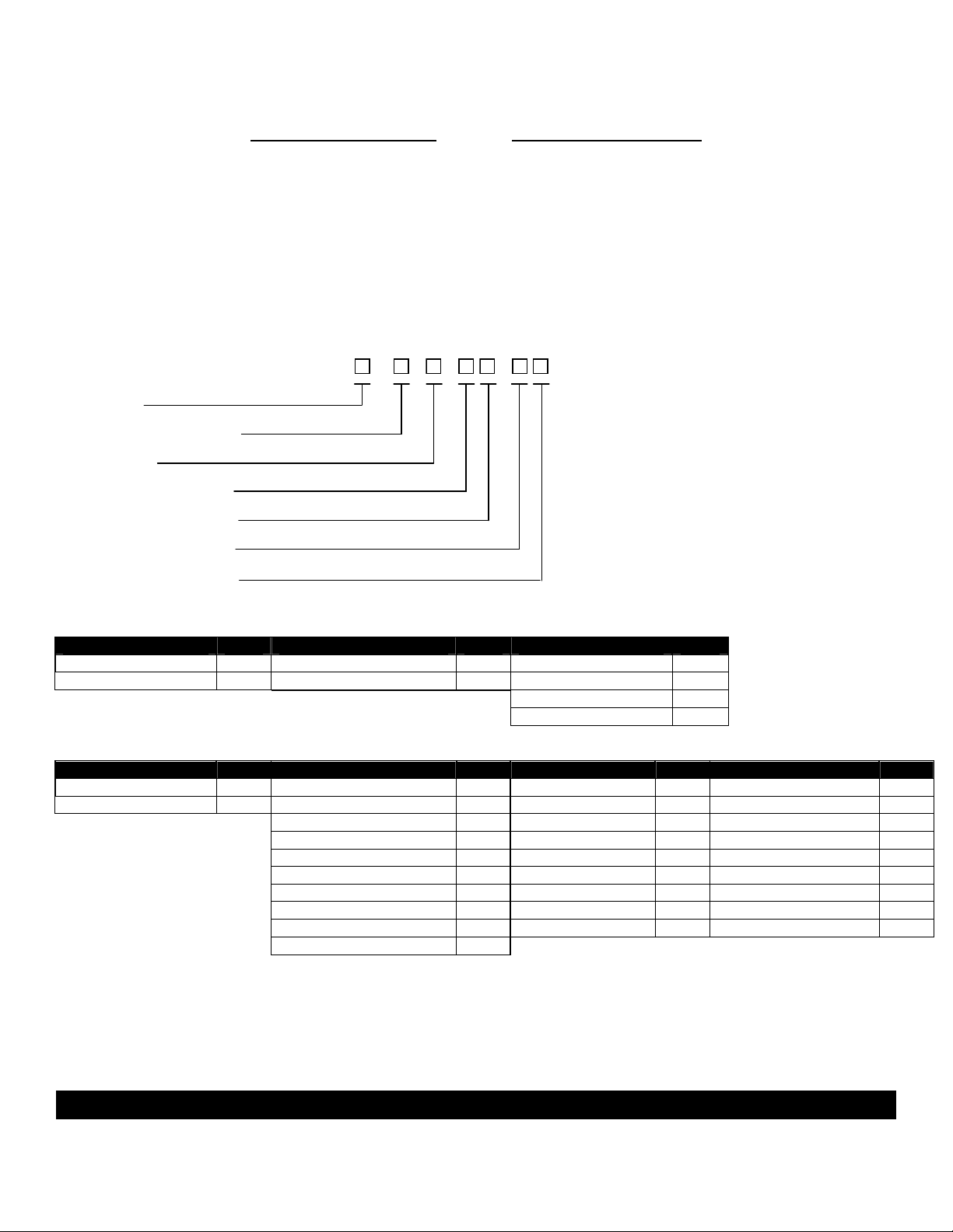
MODEL CONFIGURATOR
K
Valve Type
Gauge Connection Style
Construction
Gauge Connection Size
Gauge Connection Type
Vessel Connection Size
Vessel Connection Type
Valve Type Gauge Connection Style Valve Construction
Type Code Style Code Construction Code
Medium Pressure M Rigid R
High Pressure H Union U
Size Code Type Code Size Code Type Code
1/2" 50 NPTF N 1/2" 50 Union (NPTM) M
3/4" 75 Union (NPTM) M 3/4" 75 Union (NPTF) W
Union (NPTF) W 1" 1 Socketweld (Male) T
Socketweld (Male) T 1-1/2" 15 150# ANSI Flange A
150# ANSI Flange A 2" 2 300# ANSI Flange B
300# ANSI Flange B 3" 3 600# ANSI Flange C
600# ANSI Flange C 4" 4 900# ANSI Flange D
900# ANSI Flange D 6" 6 1500# ANSI Flange E
1500# ANSI Flange E 8" 8 2500# ANSI Flange F
2500# ANSI Flange F
Gauge Connection Size/Type Vessel Connection Size/Type
INSPECTION & DELIVERY
Upon receiving the valves, check all components carefully for damage incurred in shipping. Notify the shipping company
immediately of any such damage, and request a damage inspection. Confirm that the valve model number and
pressure/temperature ratings (located on the nameplate) match the application conditions. Also, confirm that the valve
materials are compatible with the process media and the environmental conditions.
CAUTION – Kenco valves are not to be used with lethal substances as defined by ASME Section VIII.
V
-
-
Page 1
-
Carbon Steel C
Stainless Steel Wetted W
All Stainless Steel A
Special X
Page 2
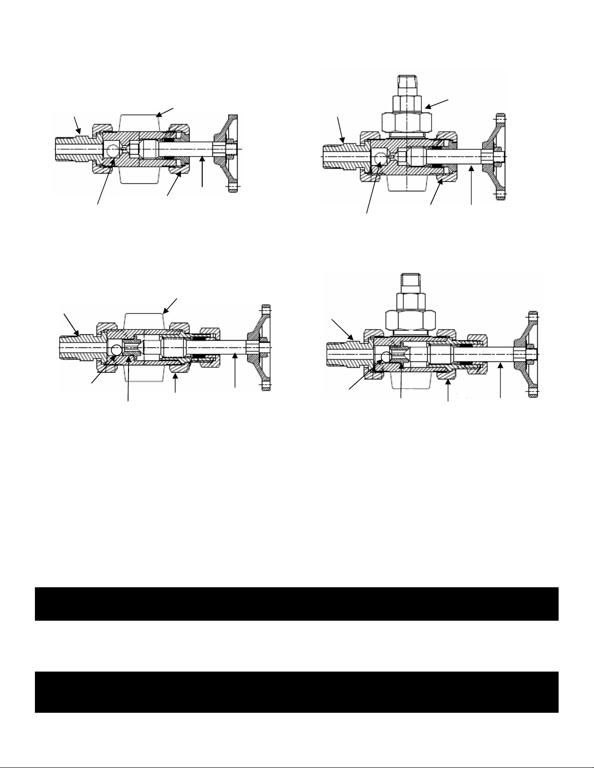
VALVE CONSTRUCTION
Model KMVR
Valve
Model KMVU Valve
Valve Stem
Vessel Connection
Vessel Connection
Valve Stem
Model KHVR
Valve
Model KHVU
Valve
Valve Stem
Vessel Connection
Valve Seat
Vessel Connection
Valve Stem
Valve Seat
Adjustable Union
Adjustable Union
BEFORE YOU INSTALL THE GAUGE VALVES
Consider the following:
OPERATION
For protection during shipping, the packing gland is loosened and the stem is in the open position. Adjust the stem and
packing after installation. Do not tighten the packing any more than is needed to stop leakage. Slowly open the valves
carefully, and wait until the gauge is fully warmed up before completely opening the valves. Kenco
Ball Check
Ball Check
Renewable
• To avoid imposing piping strains on the valves, connect and mount the valves so that they do not support the
piping.
• Support brackets should be considered for gauges over four feet in length or over 100 pounds in weight,
especially when the gauge is exposed to vibration. These support brackets will prevent overloading the
connecting valves and piping and prevent damage to the gauge from excessive vibration.
• Always provide shutoff valves between the gauge and vessel. Kenco automatic ball check valves are
recommended to provide protection against physical injury and loss of product if glass breakage should occur.
These valves also provide a means to isolate the gauge for maintenance.
CAUTION – Rapid opening of connecting valves can cause glass breakage and / or possible injury to
personnel. Gauges should be brought into service slowly.
CAUTION – While the valves are in operation they must be in their fully open position. A partially open valve
will prevent the automatic ball checks from seating, which could result in physical injury to
personnel and loss of product.
Integral
Bonnet
Fixed Gauge
Connection
Fixed Gauge
Connection
Union
Bonnet
Adjustable Union
Adjustable Union
Ball Check
Page 2
Ball Check
Renewable
Integral
Bonnet
Union Gauge
Connection
Union Gauge
Connection
Union
Bonnet
Page 3

MAINTENANCE
CAUTION – Prior to any disassembly of valves, first be sure that the valves are relieved of all internal
pressure, and that the temperature is ambient, and has been drained and/or purged of any fluids.
Failure to do this may result in a sudden release of pressure and/or physical injury to personnel.
CAUTION – When the gauge glass fails causing the ball checks to seat, closing the valve will allow fluid to
flow from the vessel during that period when the stem pin pushes the ball check off its seat and
before the stem has contacted the seat. Personnel can be injured if they don’t realize what is
happening. Fires could result if hazardous liquids are involved.
A. Replace Stem Packing
Close valves and drain fluid. Disengage packing gland nut and pull the packing gland out of stuffing box. Remove
and discard old packing and insert new packing. Put the packing gland and packing gland nut into position, and
tighten the nut. The packing gland nut should be tightened enough to stop leakage around the stem without causing
excessive binding of the stem during operation.
Packing
Gland
Packing
Packing Gland
Nut
B. Replace Valve Seat (KHVR & KHVU Valves Only)
Close valves and drain fluid. Disengage the sleeve nut from the valve body and remove the stem, sleeve, sleeve
nut, packing gland, and packing gland nut as a unit from the valve (see page #4 for details). Use a standard 5/8”
socket wrench to remove the seat. Before replacing the seat, apply lubricant (Molykote “G” or equivalent) to the
threads to prevent seizure of the seat to the valve body. Tighten the seat well, to prevent leakage. Replace the
stem unit in the valve body and tighten the sleeve nut.
WARNING –During system shutdown, it is best to leave shutoff valves open. The equipment then cools and
depressurizes along with the rest of the system. Keeping valves closed during shutdown can
trap high pressure liquid in the valves.
Page 3
Page 4

Valve Seat
Stem
Sleeve Nut
Packing Gland
Renewable
Packing Gland
Nut
Sleeve
Page 4
 Loading...