

Page 1
KENCO CHEMICAL INJECTOR
Purpose
These instructions are designed to provide the operator with factory recommended operation and
maintenance instructions for safe use. This equipment is designed with adequate safety factors;
however, do not exceed factory recommended specifications under any circumstances. Should any
special questions arise concerning the Kenco Chemical Injector or its use, contact Kenco Engineering or
its nearest factory representative.
Preliminary Considerations
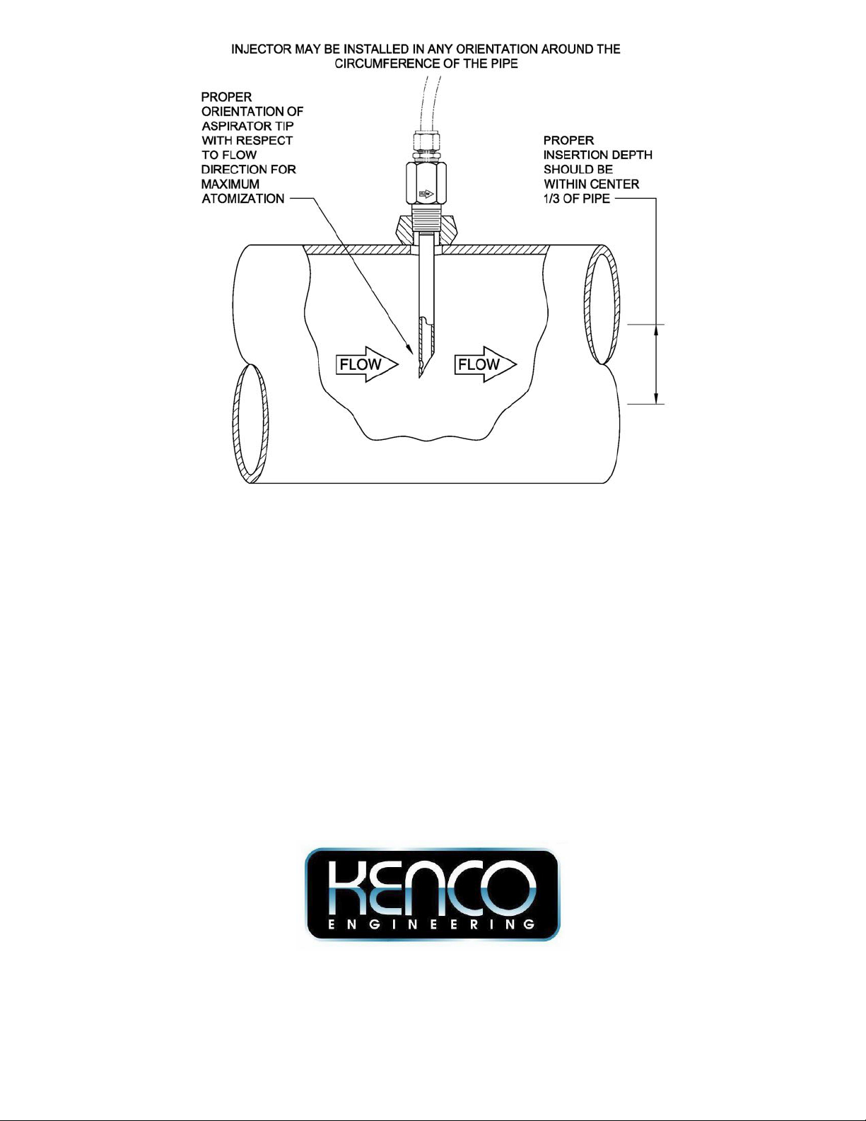
1. Although all Kenco Chemical Injectors may be installed in any orientation and at any angle around
the pipe, it is best to install it in a location which will allow operator access. Make sure that
adequate clearance is available for insertion and removal.
2. This equipment is designed to be installed in a standard NPT branch connection.
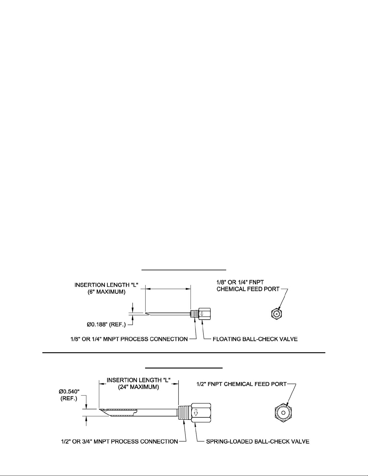
3. The Miniature KINJM Injector with a 1-7/8” insertion length (option L1.875) is designed for pipe
sizes up to 3”. Custom insertion lengths up to 6” are available. If the Miniature Injector is installed
in a vertical orientation (10 o’clock to 2 o’clock), the internal pipe pressure must exceed 0.05 psig
(1.5 inches water column) to maintain the ball check against its seat. This restriction is not
applicable to the Standard KINJ Injector.
4. The Standard KINJ Injector with a 3” insertion length (option L3.000) is designed for installation in 4”
to 6” pipe. The 5” insertion length (option L5.000) is designed for installation in 8” through 12” pipe.
Custom insertion lengths up to 24” are available.
5. For all injectors the insertion depth should be within the center 1/3 of the pipe.
6. The Chemical Injector is designed to support its own weight. Do not install in a location where it
may be used as a footrest or a hand hold. Do not hang or support any other piping, tubing or
electrical equipment from this assembly.
Miniature KINJM Injector
Standard KINJ Injector
Page 2
Installation
1. Inspect Chemical Injector for any possible damage incurred during shipment.
2. Apply thread sealant to male pipe threads on the Chemical Injector and install into pipeline.
3. Install the Injector so that the “FLOW” arrow on the check valve body is facing in the direction of
flow. This positions the aspirator and injector tip angle for optimal chemical dispersion. NOTE: For
injectors made of CPVC, an orientation groove is provided instead of a “FLOW” arrow. Install the
injector so that the orientation groove is facing upstream.
4. Apply thread sealant to male pipe threads on mating fitting and install into the injector FNPT
chemical feed port.
Removal
1. Blow down pipeline section before removing Chemical Injector. CAUTION: Loosening the MNPT
process pipe connection can result in a hazardous condition in which pressurized fluids may be
released and which may result in injury or damage.
2. Remove attached components and mating fittings.
3. Carefully remove injector.
P.O. Box 470426
Tulsa, OK 74147-0426
Phone (918) 663-4406
Fax (918) 663-4480
E-mail: info@kenco-eng.com
http://www.kenco-eng.com
67090
(02-27-13)
 Loading...