

Page 1
KENCO ENGINEERING COMPANY
P.O. BOX 470426, TULSA, OK 74147-0426
PHONE: (918) 663-4406 FAX: (918) 663-4480
http://www.kenco-eng.com e-mail: info@kenco-eng.com
CALIBRATION POT MAINTENANCE INSTRUCTIONS
Note: do not proceed with any maintenance unless gauge has been relieved of
all pressure or vacuum and has been allowed to reach Ambient temperature.
Calibration Pot should also be flushed out to remove any hazardous liquids
before handling if possible.
1. Cleaning inside of sight tube can be done without removal
of tube itself. This can be accomplished by using a tube
brush with access through 1/4” FNPT vent/drain connection
ports on each end of gauge.
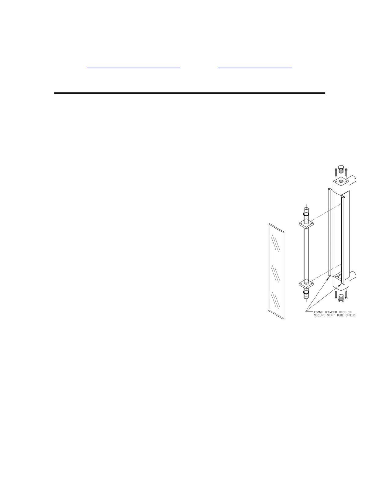
2. Removal of sight tube contained inside gauge frame is as
follows:
A. Remove existing clear polycarbonate or expanded
metal shield by bending crimped portion of gauge frame
on each end away from shield so it can easily slide out.
B. Remove (2) hex socket head cap screws in blocks
on each end of gauge holding 1-3/8” square x 1/4” thick
o-ring compression plates in place.
C. Push sight tube up into upper block as far as is
required to enable lower end of sight tube to swing out
from frame inside gauge frame.
D. Carefully lower sight tube out of block in upper end
of gauge frame.
E. Remove o-ring compression plates and seals from sight tube.
3. Installation of sight tube is as follows:
A. Slide 1-3/8” square x 1/4” thick o-ring compression plate onto each end of
sight tube.
B. Slide o-ring seal onto each end of sight tube.
C. Push end of sight tube into hole in block inside frame on upper end of gauge
as far as is required to enable lower end of sight tube to swing over and into
hole in block inside frame on lower end of gauge..
D. Install hex socket head cap screws into blocks on each end of gauge and
thread into holes in 1-3/8” square x 1/4” thick O-ring compression plates and
tighten securely.
 Loading...