

Page 1

KENCO ENGINEERING COMPANY
P.O. BOX 470426, TULSA, OK 74147-0426
PHONE: (918) 663-4406 FAX: (918) 663-4480
http://www.kenco-eng.com e-mail: info@kenco-eng.com
INSTALLATION & OPERATIONS MANUAL
FOR SIGHT FLOW INDICATORS
** IMPORTANT: Not Recommended For Steam Service Applications.
STORAGE AND HANDLING
All units should be inspected for damage upon receipt in case it may be necessary to
submit a claim to the carrier. Units should be stored where they will be protected
from the elements and corrosive fumes. Proper storage should ensure that damage
resulting from impact is completely avoided. Care should be taken to protect the end
connections from damage. Under no circumstances should the glass ever have
objects placed on top of it or be struck by other objects.
INSTALLATION INSTRUCTIONS
All units should be checked to ensure that they contain no foreign matter and that the
end connections are clean, undamaged, and in line with the adjoining pipe. Using a
flashlight, examine the glass carefully for any indications of scratches or cloudiness,
if any type of flaw is apparent, the unit must not be installed until the glass has been
replaced.
Prepare proper supports to ensure that pipeline stresses will not be transmitted to the
sight flow indicator. Any misalignment between adjacent connections must be
corrected rather than forcing a fit-up. Large, heavy units must be independently
supported to avoid stressing the piping. Be certain that the installation location
provides access for comfortable viewing and maintenance. Keep in mind that the
units must be placed so that damage cannot be inflicted by passing traffic.
Considerations should be given to locations where the glass will not be subjected to
extreme temperature variations. For instance, an indicator must not be placed in a hot
process line where the opening of a door could inflict sudden blasts of cold air. Cold
“wash down” water is also a frequent enemy of glass in hot pipelines. A poor choice
of installation could impose conditions of thermal shock (I.E. rapid heating) where
the stress values approach twice those caused by temperature alone and are additives
to mechanical stresses caused by pressure and bolting loads.
MODEL SPECIFIC INSTRUCTIONS
Page 2

FVSF/ASF: These low pressure type sight flow indicators used for both horizontal
and vertical flow, must not be installed where mechanical strains are present in the
pipelines. Any pipeline stresses imposed on these units will greatly affect the
reliability of the glass.
START-UP
*** CAUTION: Prior to start up compare the data on the information tag to the
conditions of the system. If any discrepancy is apparent, contact KENCO for
clarification and advice.
Gaskets and seals frequently assume a compression-set (loss of resiliency) over a
period of time. Some materials tend to compression-relieve or creep. It is
recommended that the unit have its glass retainer fasteners retorqued to the proper
value before start-up.
*** CAUTION: Do not tighten any fasteners while the equipment is in operation.
Check the glass in the unit prior to start-up to ensure that there are no chips, scratches,
or blemishes. Use a flashlight or another source of bright concentrated light to
examine the glass carefully. If any type of flaw is apparent, start-up should be delayed
pending the replacement of the glass and gaskets.
MAINTENANCE
Periodic visual inspections should be made to ensure that no leaks are evident and
that there is no clouding, scratching, or blemishing of the glass. In new installations,
daily inspections are recommended to establish a routine inspection cycle.
Keep glasses clean, using commercial glass cleaners. Cleaning must be done without
removing the glass. Never use harsh abrasives, wire brushes, steel wool, metal
scrapers or other materials could scratch the glass.
*** CAUTION: Do not attempt to clean when the equipment is in operation.
A. GLASS INSPECTION
To examine for scratches, shine a bright concentrated light at about a 45 degree angle
to the glass. Anything that glistens brightly must be looked at closely. Any scratch
that glistens and catches a fingernail is cause for glass replacement. If the inner
surface appears cloudy or roughened and will not respond to cleaning procedures, the
glass must be replaced, since this is evidence of a chemical attack.
B. GLASS REMOVAL
Page 3

Once a glass has been removed from its mounting in process equipment, regardless of
the reason for removal, discard it and substitute a new piece. Used glass may contain
hidden damage. Be sure that the glass is appropriate for the service application.
Check any in-line safety devices for compatibility with temperature and pressure
limitations of the glass. If glass is removed, protective shields to keep cold air, water
or falling objects form damaging the glass must be put back into position. Gaskets
must always be replaced with gaskets of the same material once a unit has been
disassembled.
SERVICE INSTRUCTIONS
A. DISASSEMBLY
The units must be removed from the line and bench disassembled. Remove the heads
by removing the cap screws or nuts on all models. Carefully remove the glass,
gaskets and other hardware. Place everything on a clean work surface.
B. INSPECTION
The glass seating surfaces in the body and in the retainer should be carefully cleaned
and checked to insure that there are no pieces of old gasket material, chips, residue,
dirt or other material on the surfaces. Any foreign particles left on the surface could
cause high local stresses in the glass, possibly resulting in its failure.
CRACKED GLASS CAN BE CAUSED BY THE FOLLOWING:
1. Pressure in excess of the glass rating
2. High local stresses, which can be due to uneven bolt torquing or foreign particles
on the glass seating surface.
3. Thermal shock of the glass.
It is important to determine the cause of the glass crack. Simply putting in a new
glass will not alleviate the cause for placement. Consultation with the manufacturer
may greatly extend the service life and reliability of the units in service. Check your
operating conditions against the ratings on the unit’s nameplate or accompanying
literature. If there are any questions about the ratings of the unit for the service
intended, do not proceed without verifying the unit applicability with the maintenance
supervisor or engineer.
C. GENERAL REASSEMBLY INSTRUCTIONS
Always reassemble sight flow indicators using new glass and gaskets. The potential
of hidden damage makes used glass and gaskets an extreme safety risk. Check the
new glass to ensure that there are no bumps, chips, scratches or other imperfections.
Be certain that the gaskets are clean.
The glass and gaskets should be verified as correct for the application. Generally, a
direct replacement of the glass and gaskets that were in the unit before disassembly
should be correct, but you should check with the maintenance supervisor to avoid a
costly mistake.
Page 4
Use only gaskets that have been specified by the manufacturer or the supervising
engineer. Be certain that they are clean and fresh with no bumps, tears or serious
imperfections.
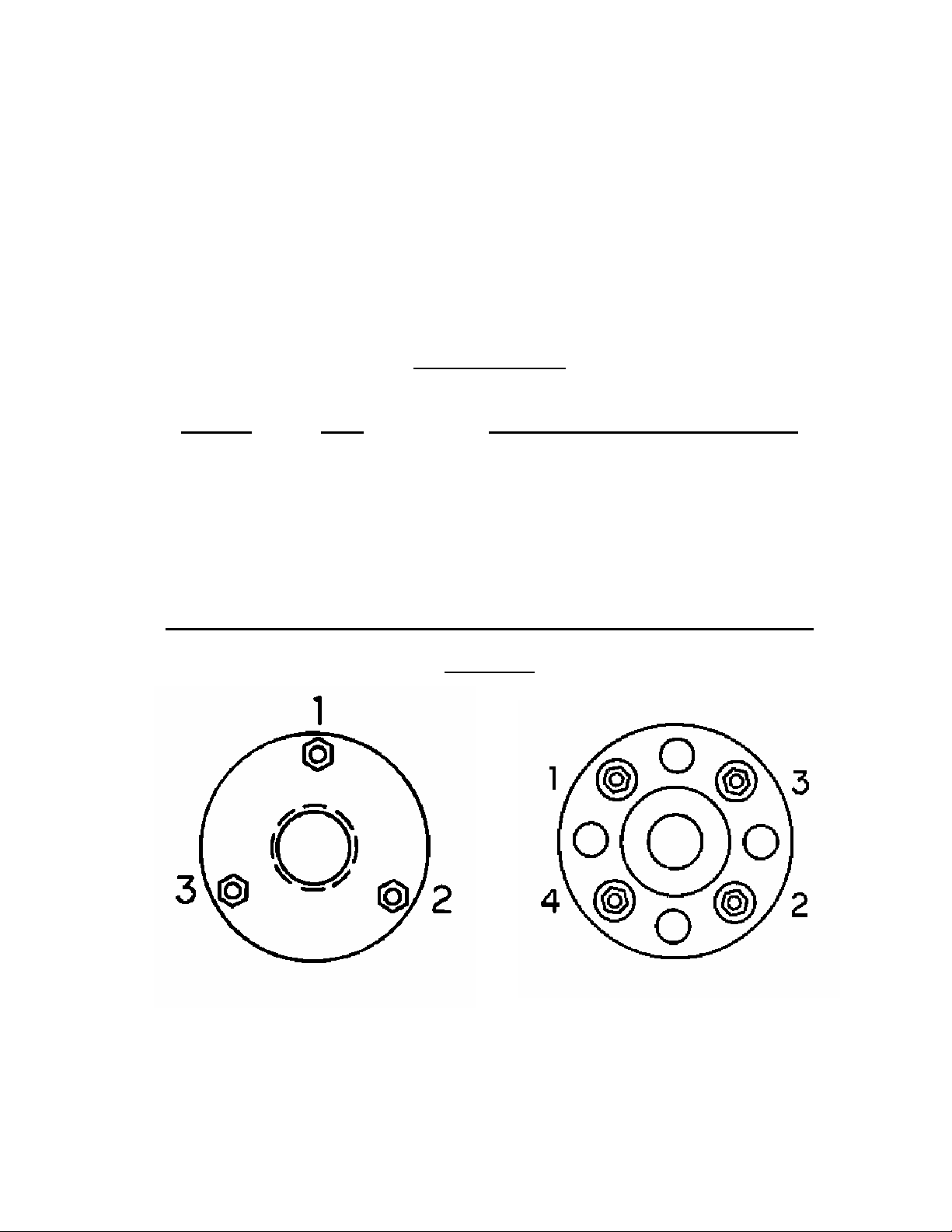
Using a torque wrench, tighten the fasteners in a regular pattern to avoid uneven loads
on the glass. (For Typical Tightening Patterns, See Figure A) It is necessary to torque
individual fasteners in small amounts, moving to the next fastener after each
increment of torque. A maximum difference of 3 FT-LBS. between fasteners should
be maintained on larger units; there should be less on smaller units. Continue
torquing until the value recommended for the unit is attained (See Torque Chart).
TORQUE CHART
TORQUE PER FASTNER
MODEL SIZE NEOPRENE & PTFE/NEO. GASKET
FVSF ALL 14 FT-LB
ASF ½” & ¾” 5 FT-LB
ASF 1” 8 FT-LB
ASF 1 ½” 10 FT-LB
ASF 2” 12 FT-LB
ASF 2 ½” & 3” 14 FT-LB
FIGURE A
 Loading...